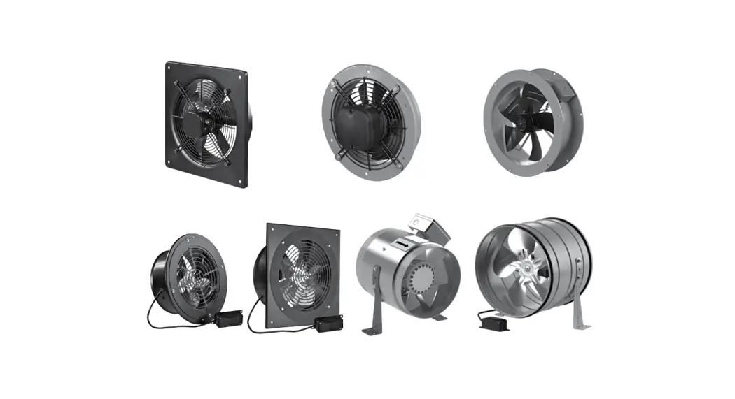
![]() Industrial Electric Axial Fans
Industrial Electric Axial Fans
User Manual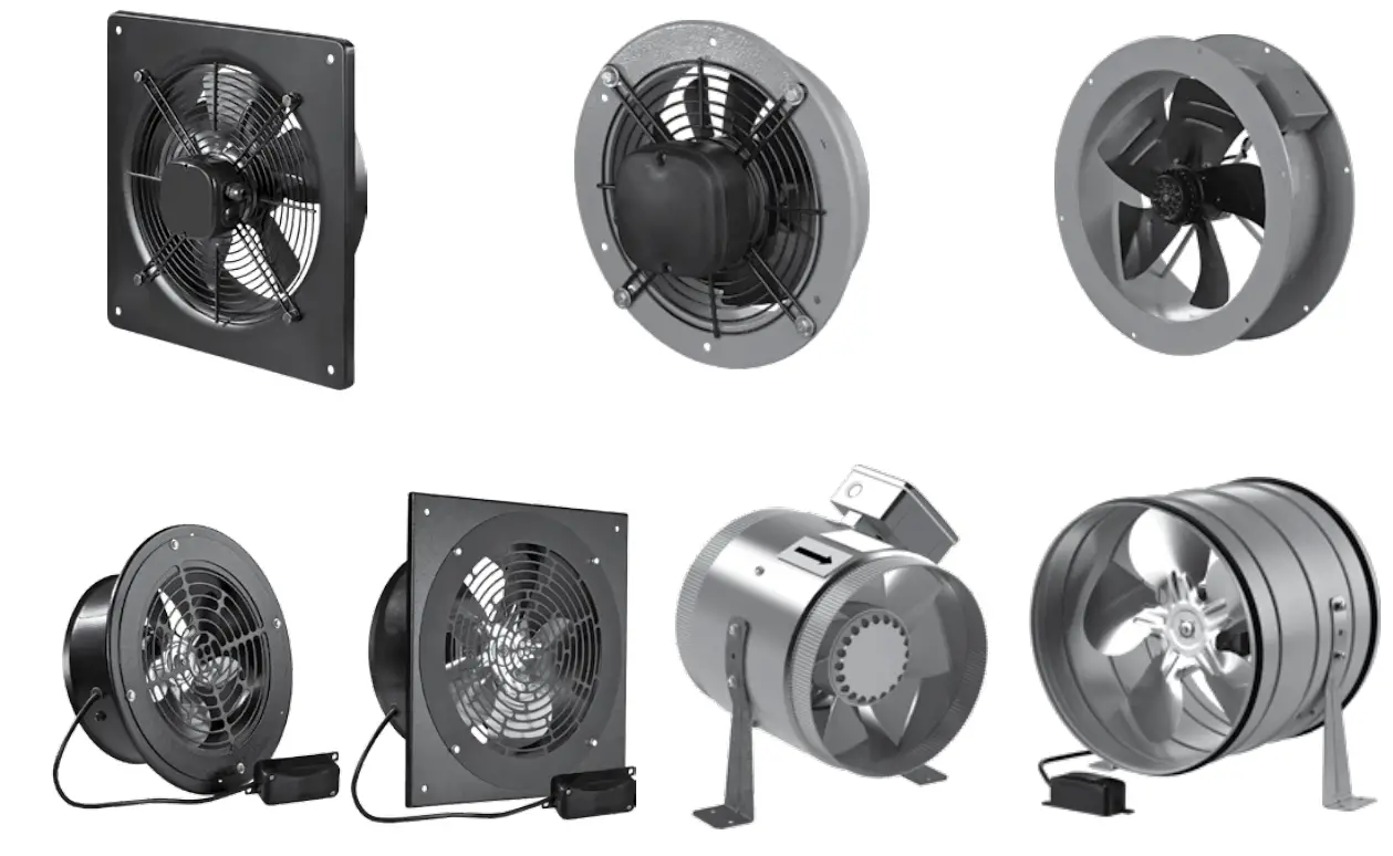
IndustrIal electrIc axIal fans
axis-Q……………. axis-Qra
axis-Qr…………. tubo-f
axis-f………….. tubo-M(Z)
axis-Qa………… tubo-Ma(Z)
www.blaubergventilatoren.de
This user’s manual is a main operating document intended for technical, maintenance, and operating staff. The manual contains information about purpose, technical details, operating principle, design, and installation of the Axis-Q / Axis-QR / Axis-F / Axis-QA / Axis-QRA / Tubo-F / Tubo-M(Z) / Tubo-MA(Z) unit and all its modifications. Technical and maintenance staff must have theoretical and practical training in the field of ventilation systems and should be able to work in accordance with workplace safety rules as well as construction norms and standards applicable in the territory of the country.
SAFETY REQUIREMENTS
- Please read the user’s manual carefully prior to installing and operating the unit.
- All user’s manual requirements as well as the provisions of all the applicable local and national construction, electrical, and technical norms and standards must be observed when installing and operating the unit.
- The warnings contained in the user’s manual must be considered most seriously since they contain vital personal safety information.
- Failure to follow the rules and safety precautions noted in this user’s manual may result in an injury or unit damage.
- After a careful reading of the manual, keep it for the entire service life of the unit.
- While transferring the unit control, the user’s manual must be turned over to the receiving operator.
UNIT INSTALLATION AND OPERATION SAFETY PRECAUTIONS
- Disconnect the unit from power mains prior to any installation operations
- Unpack the unit with care.
- The unit must be grounded!
- While installing the unit, follow the safety regulations specific to the use of electric tools.
- Do not change the power cable length at your own discretion.
- Do not bend the power cable.
- Avoid damaging the power cable.
- Do not put any foreign objects on the power cable.
- Do not lay the power cable of the unit in close proximity to heating equipment.
- Do not use damaged equipment or cables when connecting the unit to power mains.
- Do not operate the unit outside the temperature range stated in the user’s manual.
- Do not operate the unit in aggressive or explosive environments.
- Do not touch the unit controls with wet hands.
- Do not carry out the installation and maintenance operations with wet hands.
- Do not wash the unit with water.
- Protect the electric parts of the unit against ingress of water.
- Do not allow children to operate the unit.
- The unit is allowed to be used by children aged from 8 years oldand above and persons with reduced physical, sensory, or mental capabilities or no experience and knowledge provided that they have been given supervision or instruction regarding safe use of the unit and understand the risks involved.
- Disconnect the unit from power mains prior to any technical maintenance.
- Do not store any explosive or highly flammable substances in close proximity to the unit.
- When the unit generates unusual sounds, odour, or emits smoke, disconnect it from power supply and contact the Seller.
- Do not open the unit during operation.
- Do not direct the air flow produced by the unit towards open flame or ignition sources.
- Do not block the air duct when the unit is switched on.
- In case of continuous operation of the unit, periodically check the security of mounting.
- Do not sit on the unit and avoid placing foreign objects on it.
- Use the unit only for its intended purpose.
![]() THE PRODUCT MUST BE DISPOSED SEPARATELY AT THE END OF ITS SERVICE LIFE. DO NOT DISPOSE THE UNIT AS UNSORTED DOMESTIC WASTE.
THE PRODUCT MUST BE DISPOSED SEPARATELY AT THE END OF ITS SERVICE LIFE. DO NOT DISPOSE THE UNIT AS UNSORTED DOMESTIC WASTE.
PURPOSE
![]() THE UNIT SHOULD NOT BE OPERATED BY CHILDREN OR PERSONS WITH REDUCED PHYSICAL, MENTAL, OR SENSORY CAPACITIES, OR THOSE WITHOUT THE APPROPRIATE TRAINING.
THE UNIT SHOULD NOT BE OPERATED BY CHILDREN OR PERSONS WITH REDUCED PHYSICAL, MENTAL, OR SENSORY CAPACITIES, OR THOSE WITHOUT THE APPROPRIATE TRAINING.![]() THE UNIT MUST BE INSTALLED AND CONNECTED ONLY BY PROPERLY QUALIFIED PERSONNEL AFTER THE APPROPRIATE BRIEFING.
THE UNIT MUST BE INSTALLED AND CONNECTED ONLY BY PROPERLY QUALIFIED PERSONNEL AFTER THE APPROPRIATE BRIEFING.![]() THE CHOICE OF UNIT INSTALLATION LOCATION MUST PREVENT UNAUTHORISED ACCESS BY UNATTENDED CHILDREN.
THE CHOICE OF UNIT INSTALLATION LOCATION MUST PREVENT UNAUTHORISED ACCESS BY UNATTENDED CHILDREN.
Industrial electric axial fans are designed for direct extraction of indoor air outdoors and supply of fresh outdoor air into the premises. The unit is a component part and is not designed for stand-alone operation.
The unit is rated for continuous operation.
Transported air must not contain any flammable or explosive mixtures, evaporation of chemicals, sticky substances, fibrous materials, coarse dust, soot and oil particles or environments favorable for the formation of hazardous substances (toxic substances, dust, pathogenic germs).
DELIVERY SET
Axis-Q / Axis-QR / Axis-F / Axis-QA / Axis-QRA
| NAME | NUMBER |
| Fan | 1 piece |
| User’s manual | 1 piece |
| Packing | 1 piece |
Tubo-F / Tubo-M(Z) / Tubo-MA(Z)
| NAME | NUMBER |
| Fan | 1 piece |
| Mounting brackets | 2 pieces |
| User’s manual | 1 piece |
| Packing | 1 piece |
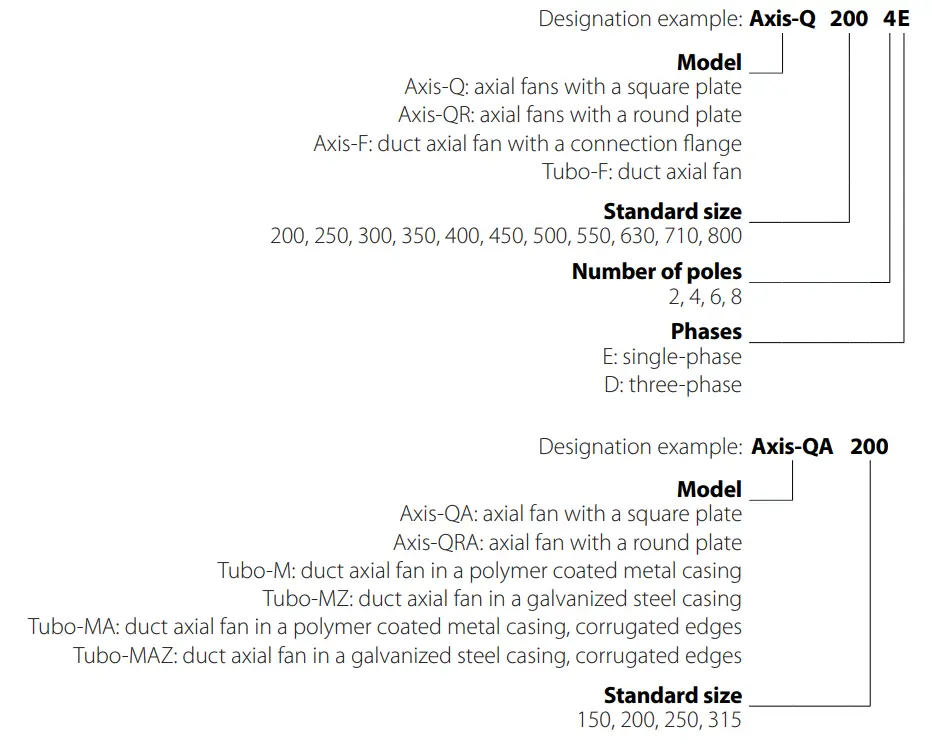
DESIGNATION KEY
TECHNICAL DATA
The unit is rated as a Class I electrical appliance.
The corrosive aggressiveness of the handled medium to carbon steels of ordinary quality must be equal to that of air at temperatures ranging from -25 °C to +40/60 °C. In addition to that the handled media must be free from dust and other hard impurities as well as sticky substances and fibrous materials.
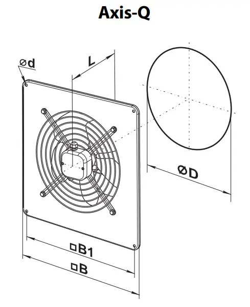
| Model | Dimensions [mm] | Weight [kg] | ||||
| Ø D | Ø d | B | B1 | L | ||
| Axis-Q 200 2E | 210 | 7 | 312 | 260 | 125 | 3.0 |
| Axis-Q 250 2E / Axis-Q 250 2D | 260 | 7 | 370 | 320 | 135 | 4.0 |
| Axis-Q 250 4E / Axis-Q 250 4D | 260 | 7 | 370 | 320 | 135 | 3.5 |
| Axis-Q 300 4E / Axis-Q 300 4D | 317 | 9 | 430 | 380 | 145 | 6.1 / 5.4 |
| Axis-Q 300 4E / Axis-Q 300 4D | 317 | 9 | 430 | 380 | 145 | 5.0 / 5.4 |
| Axis-Q 350 4E / Axis-Q 350 4D | 374 | 9 | 485 | 435 | 165 | 7.8 |
| Axis-Q 400 4E / Axis-Q 400 4D | 416 | 9 | 540 | 490 | 220 | 8.8 |
| Axis-Q 450 4E / Axis-Q 450 4D Axis-Q 450 6E / Axis-Q 450 6D | 465 | 11 | 576 | 535 | 230 | 10.5 |
| Axis-Q 500 4E / Axis-Q 500 4D Axis-Q 500 6E / Axis-Q 500 6D | 520 | 11 | 655 | 615 | 250 | 14.0 |
| Axis-Q 550 4E / Axis-Q 550 4D Axis-Q 550 6E / Axis-Q 550 6D | 570 | 11 | 725 | 675 | 260 | 16.5 |
| Axis-Q 630 4E / Axis-Q 630 4D Axis-Q 630 6E / Axis-Q 630 6D | 650 | 11 | 800 | 710 | 275 | 20.0 |
| Axis-Q 710 6D / Axis-Q 710 8D | 725 | 13 | 900 | 810 | 350 | 33.0 |
| Axis-Q 800 6D / Axis-Q 800 8D | 800 | 13 | 970 | 910 | 350 | 44.0 |
| Model | Dimensions [mm] | Weight [kg] | ||||
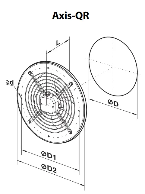
| Ø D | Ø D1 | Ø D2 | Ø d | L | ||
| Axis-QR 200 2E | 210 | 250 | 280 | 7 | 125 | 2.8 |
| Axis-QR 250 2E / Axis-QR 250 2D | 260 | 295 | 340 | 7 | 135 | 3.8 |
| Axis-QR 250 4E / Axis-QR 250 4D | 260 | 295 | 340 | 7 | 135 | 3.4 |
| Axis-QR З00 2E / Axis-QR 300 2D | 317 | 380 | 397 | 9 | 145 | 5.9 / 5.1 |
| Axis-QR З00 4E / Axis-QR 300 4D | 317 | 380 | 397 | 9 | 145 | 5.0 / 5.1 |
| Axis-QR 350 4E / Axis-QR 350 4D | 374 | 442 | 460 | 9 | 165 | 7.5 |
| Axis-QR 400 4E / Axis-QR 400 4D | 417 | 504 | 528 | 9 | 220 | 8.5 |
| Axis-QR 450 4E / Axis-QR 450 4D Axis-QR 450 6E / Axis-QR 450 6D | 465 | 578 | 607 | 11 | 230 | 10.0 |
| Axis-QR 500 4E / Axis-QR 500 4D Axis-QR 500 6E / Axis-QR 500 6D | 520 | 590 | 655 | 11 | 250 | 14.0 |
| Axis-QR 550 4E / Axis-QR 550 4D Axis-QR 550 6E / Axis-QR 550 6D | 570 | 645 | 710 | 11 | 260 | 16.5 |
| Axis-QR 630 4E / Axis-QR 630 4D Axis-QR 630 6E / Axis-QR 630 6D | 650 | 760 | 800 | 11 | 275 | 20.0 |
| Axis-QR 710 6D / Axis-QR 710 8D | 725 | 820 | 890 | 13 | 350 | 31.0 |
| Axis-QR 800 6D / Axis-QR 800 8D | 800 | 900 | 970 | 13 | 350 | 42.0 |
| Model | Dimensions [mm] | Weight [kg] | |||||
| Ø D | Ø D1 | Ø D2 | Ø d | B | L | ||
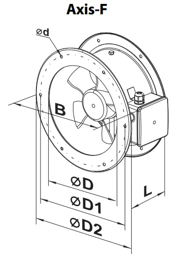
| Axis-F 200 2E | 205 | 235 | 255 | 7 | 290 | 120 | 3.0 |
| Axis-F 250 2E/Axis-F 250 2D | 260 | 286 | 306 | 7 | 340 | 150 | 3.9 |
| Axis-F 250 4E/Axis-F 250 4D | 260 | 286 | 306 | 7 | 340 | 150 | 4.0 |
| Axis-F 300 2E/Axis-F 300 2D | 310 | 356 | 382 | 7 | 410 | 160 | 6.2 / 5.7 |
| Axis-F 300 4E/Axis-F 300 4D | 310 | 356 | 382 | 7 | 410 | 160 | 6.2 |
| Axis-F 350 4E/Axis-F 350 4D | 362 | 395 | 421 | 9.5 | 450 | 160 | 7.7 |
| Axis-F 400 4E/Axis-F 400 4D | 412 | 438 | 465 | 9.5 | 500 | 170 | 8.1 |
| Axis-F 450 4E/Axis-F 450 4D Axis-F 450 6E/Axis-F 450 6D | 462 | 487 | 515 | 9.5 | 550 | 200 | 9.1 |
| Axis-F 500 4E/Axis-F 500 4D Axis-F 500 6E/Axis-F 500 6D | 515 | 541 | 570 | 9.5 | 600 | 220 | 11.0 |
| Axis-F 550 4E/Axis-F 550 4D Axis-F 550 6E/Axis-F 550 6D | 565 | 605 | 636 | 11.5 | 660 | 230 | 13.9 |
| Axis-F 630 4E/Axis-F 630 4D Axis-F 630 6E/Axis-F 630 6D | 645 | 674 | 715 | 11.5 | 740 | 250 | 16.4 |
| Axis-F 710 6D/Axis-F 710 8D | 725 | 767 | 805 | 11.5 | 835 | 250 | 30.0 |
| Axis-F 800 6D/Axis-F 800 8D | 800 | 845 | 880 | 11.5 | 910 | 280 | 40.0 |
| Model | Dimensions [mm] | Weight [kg] | ||||
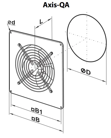
| Ø D | Ø d | B | B1 | L | ||
| Axis-QA 150 | 162 | 7 | 250 | 210 | 120 | 2.5 |
| Axis-QA 200 | 208 | 7 | 312 | 260 | 120 | 3.0 |
| Axis-QA 250 | 262 | 7 | 370 | 320 | 140 | 3.5 |
| Axis-QA 315 | 312 | 9 | 430 | 380 | 170 | 6.1 |
| Model | Dimensions [mm] | Weight [kg] | ||||
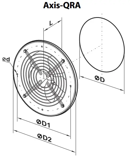
| Ø D | Ø D1 | Ø D2 | Ø d | L | ||
| Axis-QRA 150 | 162 | 190 | 220 | 7 | 120 | 2.5 |
| Axis-QRA 200 | 208 | 270 | 300 | 7 | 120 | 2.5 |
| Axis-QRA 250 | 262 | 330 | 360 | 7 | 140 | 3.0 |
| Axis-QRA 315 | 312 | 390 | 420 | 9 | 170 | 5.1 |
| Model | Dimensions [mm] | Weight [kg] | ||||
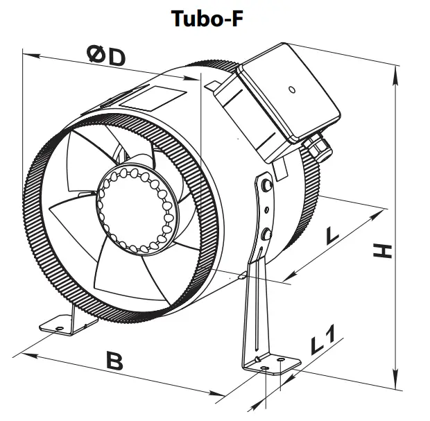
| Ø D | B | L | H | L1 | ||
| Tubo-F 200 2E | 199 | 227 | 220 | 300 | 30 | 3.5 |
| Tubo-F 250 2E | 249 | 282 | 250 | 320 | 30 | 4.5 |
| Tubo-F 250 4E | 249 | 282 | 250 | 320 | 30 | 4.5 |
| Tubo-F 300 2E | 299 | 326 | 250 | 390 | 40 | 6.3 |
| Tubo-F 300 4E | 299 | 326 | 250 | 390 | 40 | 6.3 |
| Tubo-F 350 4E | 349 | 378 | 300 | 410 | 40 | 8.4 |
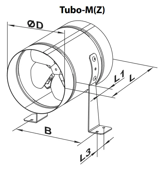
| Model | Dimensions [mm] | Weight [kg] | ||||
| Ø D | B | L | L1 | L3 | ||
| Tubo-M(Z) 150 | 162 | 183 | 220 | 40 | 30 | 1.8 |
| Tubo-M(Z) 200 | 208 | 228 | 220 | 40 | 30 | 2.4 |
| Tubo-M(Z) 250 | 262 | 283 | 270 | 55 | 30 | 3.7 |
| Tubo-M(Z) 315 | 315 | 337 | 278 | 55 | 40 | 4.9 |
The Tubo-M(Z) fans are equipped with RSM(Z) (polymer-coated steel, galvanized steel) reducers for connection to 150 mm, 200 mm and 250 mm air ducts. The reducers are not included in the delivery set and must be ordered separately.
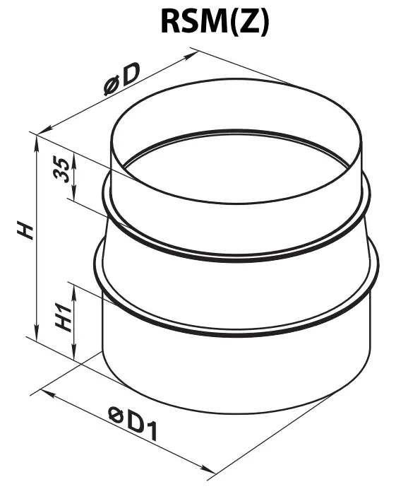
| Model | Dimensions [mm] | Weight [kg] | |||
| Ø D | Ø D1 | H | H1 | ||
| RSM(Z) 148/158 | 148 | 158 | 140 | 55 | 0.3 |
| RSM(Z) 198/204 | 198 | 204 | 140 | 55 | 0.4 |
| RSM(Z) 248/258 | 248 | 258 | 150 | 65 | 0.42 |
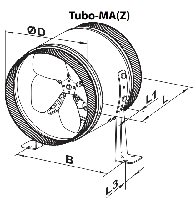
| Model | Dimensions [mm] | Weight [kg] | ||||
| Ø D | B | L | L1 | L3 | ||
| Tubo-MA(Z) 150 | 149 | 183 | 220 | 35 | 30 | 1.8 |
| Tubo-MA(Z) 200 | 299 | 228 | 220 | 35 | 30 | 2.4 |
| Tubo-MA(Z) 250 | 249 | 283 | 270 | 35 | 30 | 3.7 |
UNIT DESIGN AND OPERATING PRINCIPLE
The Axis-Q and Axis-QR fans consist of a casing 1 with a square or a round flange with a grille fixed with bolts 4 and complete with an electric motor and impeller 5. The impeller rotation direction depends on the type of electric motor and external rotor used. The bolts attaching the impeller to the grille also serve as attachment bolts for the terminal box 3. Some models may be equipped with a cable with a terminal box for remote connection. The casing has an M4 threaded hole and yellow-green cables for connection to the protective ground circuit.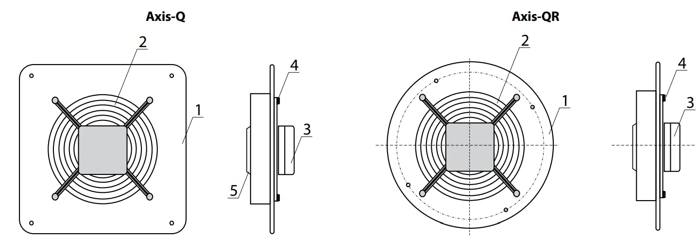
The Axis-QA and Axis-QRA fans consist of a casing 1 made of polymer-coated stainless steel with a square (Axis-QA) or round (Axis-QRA) flange, to which the grille 2 is fastened with bolts 4. The motor and impeller 5 are mounted on a bracket inside the casing. The fans are equipped with a terminal box with a cable for remote connection.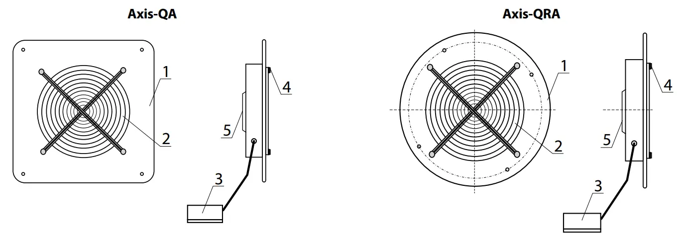
The Axis-F fan consists of a casing 1 with round flanges on both sides providing connection for a cross piece complete with an electric motor and impeller 4 fixed with bolts 3. The impeller rotation direction depends on the type of electric motor used. The electric motor casing has an M4 threaded hole and yellow-green cables for connection to the protective ground circuit.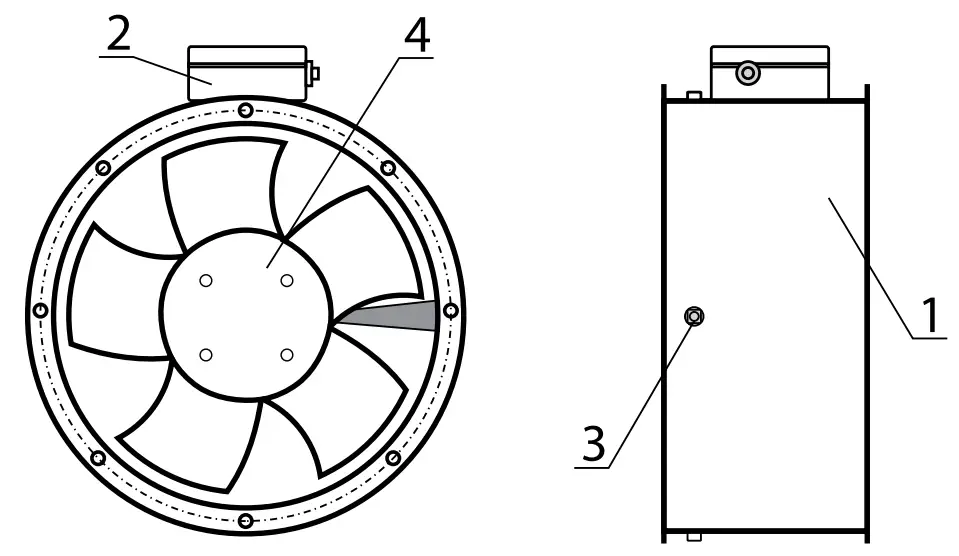
Tubo-F, Tubo-M(Z), Tubo-MA(Z) fans
The brackets 2 are attached to the casing with bolts 1. The electric motor with the impeller 4 is mounted on the bracket 3 inside the casing. The terminal box 5 mounted onto the Tubo-F fan casing provides connection to power mains.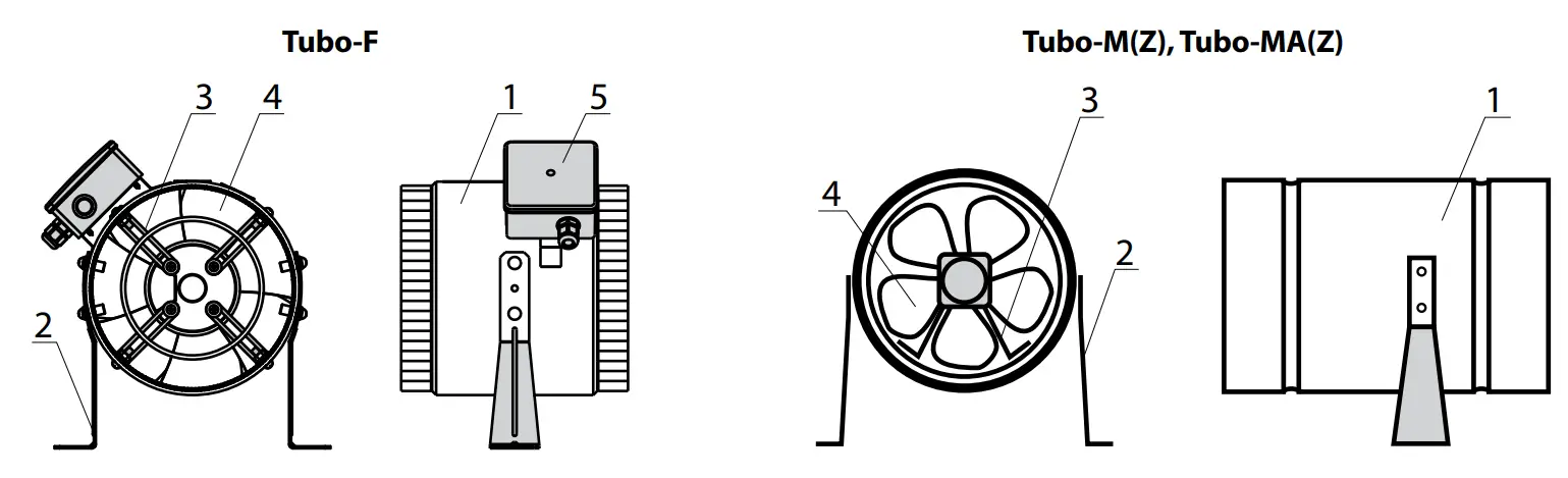
MOUNTING AND SET-UP
![]() BEFORE MOUNTING MAKE SURE THE CASING DOES NOT CONTAIN ANY FOREIGN OBJECTS (E.G. FOIL, PAPER).
BEFORE MOUNTING MAKE SURE THE CASING DOES NOT CONTAIN ANY FOREIGN OBJECTS (E.G. FOIL, PAPER).![]() WHILE INSTALLING THE UNIT ENSURE CONVENIENT ACCESS FOR SUBSEQUENT MAINTENANCE AND REPAIR.
WHILE INSTALLING THE UNIT ENSURE CONVENIENT ACCESS FOR SUBSEQUENT MAINTENANCE AND REPAIR.
- Unpack the fan and check for any cuts in the electric wires and cracks in the insulation. Inspect the fan casing to make sure it is free from any cracks and deformations. Set the impeller in motion and check that it rotates freely without catching against the inlet flange and the casing.
- Prior to powering up the fan make sure that the mains parameters comply with the technical specifications on the fan label attached to the protective casing.
- The fan mounting locations must enable adequate access for maintenance, technical service and replacement operations.
- When the service conditions may lead to water ingress, the fans must be equipped with adequate protection. For example, the fans may be installed under a canopy or a roof.
- Since the fan belongs to Class 1 in terms of electrical hazard protection proper grounding is a must: to ground the equipment, connect the terminal to the protective ground circuit.
The fans are installed on wall surfaces by means of a mounting casing with attachment holes:
- Axis-Q, Axis-QA, series with a square casing — 4 holes.
- Axis-QR, Axis-QRA series with a round casing — 6 holes.
Axis-Q fan installation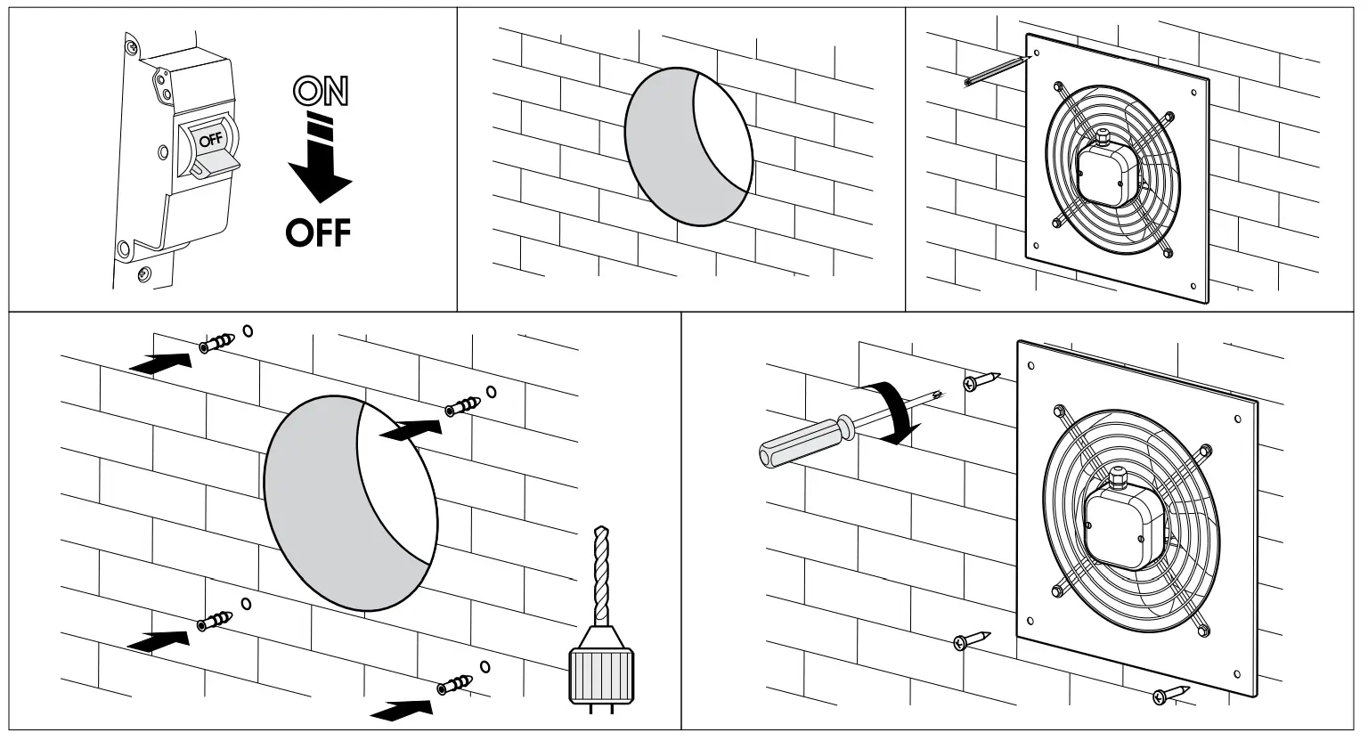
Axis-QR fan installation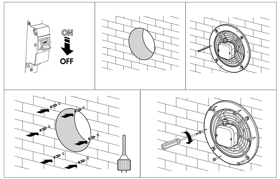
Axis-QA and Axis-QRA fan installation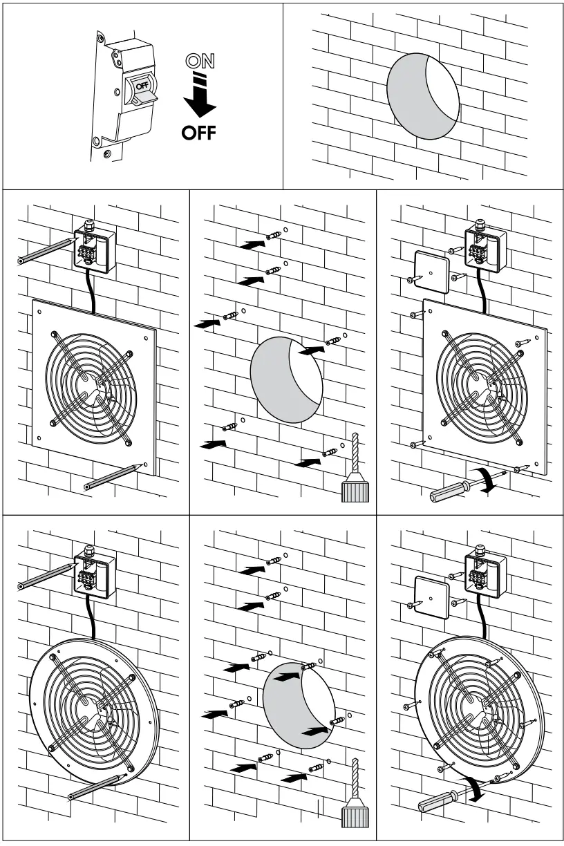
Axis-F fan installation
The fans are installed into air ducts by means of connection flanges. The fan must be installed in such a way so that the direction of the arrow shown on the casing matches the direction of air flow in the system. The power is supplied via the remote-position terminal box.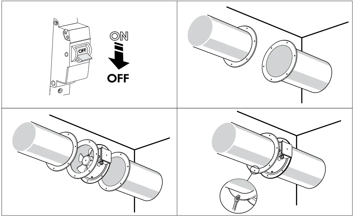
Tubo-F and Tubo-MA(Z) fan installation
The fans are installed into air ducts by means of clamps. The delivery set includes mounting brackets for attaching the units to the ceiling or a wall. The power is supplied via an external terminal box mounted to the fan casing.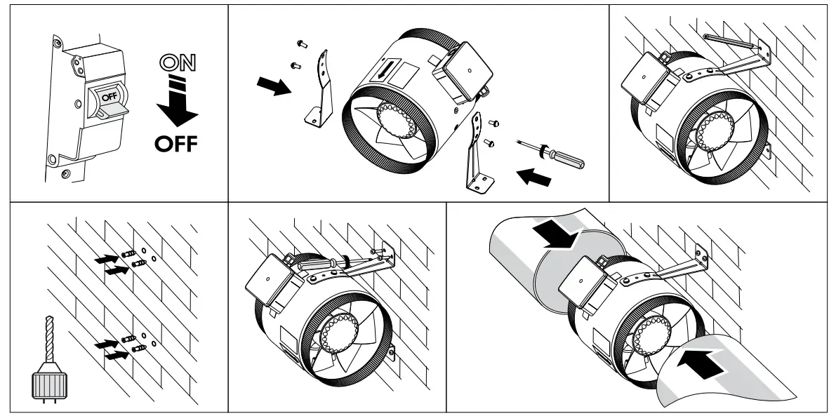
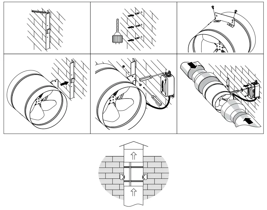
Tubo-M(Z) fan installation
The fans are installed into air duct by means of an RSM(Z) reducer which enables joining different diameter ducts. Once done, the assembly is secured with clamps. The power is supplied via terminal box on the fan casing. The Tubo-M(Z) delivery set includes mounting brackets for attaching the unit to the mounting surface. Depending on a delivery set, two mounting options are possible: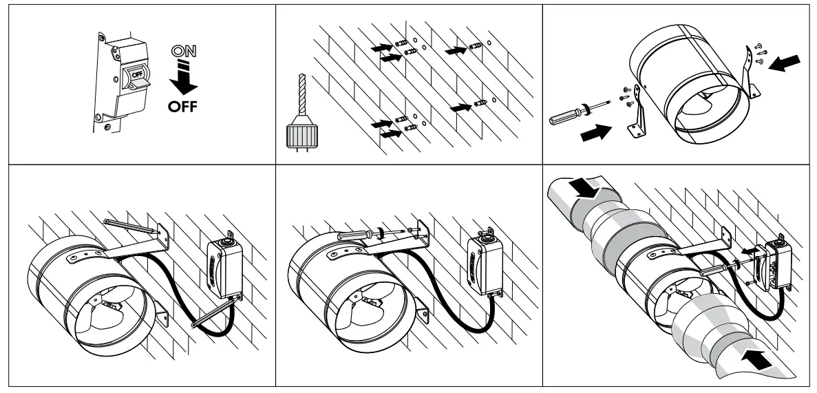 2. Note: the mounting bracket fixing point on the fan casing must be selected so that the screws do not interfere with the free rotation of the impeller.
CONNECTION TO POWER MAINS
![]() DISCONNECT THE POWER SUPPLY PRIOR TO ANY OPERATIONS WITH THE UNIT.
DISCONNECT THE POWER SUPPLY PRIOR TO ANY OPERATIONS WITH THE UNIT.
CONNECTION OF THE UNIT TO POWER MAINS IS ALLOWED BY A QUALIFIED ELECTRICIAN WITH A WORK PERMIT FOR THE ELECTRIC UNITS UP TO 1000 V AFTER CAREFUL READING OF THE PRESENT USER’S MANUAL.
THE RATED ELECTRICAL PARAMETERS OF THE UNIT ARE GIVEN ON THE MANUFACTURER’S LABEL.
- The unit is rated for connection to power mains with the parameters specified in the «Technical specifications» section, according to the wiring diagram.
- The connection must be made using durable, insulated and heat-resistant conductors (cables, wires). The actual wire cross section selection must be based on the maximum load current, maximum conductor temperature depending on the wire type, insulation, length and installation method.
- The external power input must be equipped with an automatic circuit breaker (QF) built into the stationary wiring to open the circuit in the event of overload or short-circuit. The position of the external automatic circuit breaker must ensure free access for quick power-off of the unit. The trip current of the automatic circuit breaker must exceed the maximum current consumption of the unit (refer to the «Technical data» section or to the unit label). The recommended trip current of the circuit breaker is the next current in the standard trip current row following the maximum current of the connected unit. The circuit breaker is not included in the delivery set and can be ordered separately.
| Connection of Axis-Q, Axis-QR, Axis-F, Tubo-F fans with single-phase motor | Connection of Axis-Q, Axis-QR, Axis-F fans with three-phase motor | Connection of Axis-QA, Axis-QRA, Tubo-M(Z), Tubo-MA(Z) fans with single-phase motor |
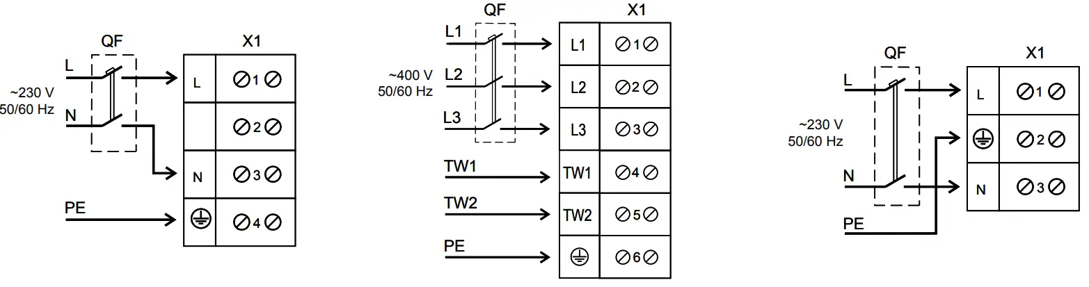 | ||
Axis-Q and Axis-QR fan connection 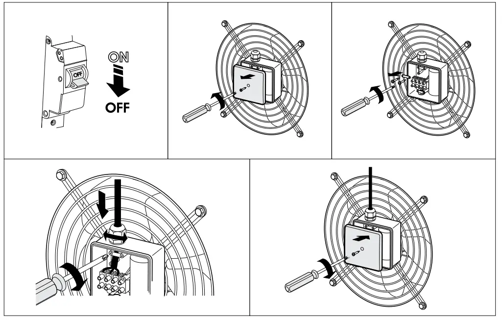 Axis-QA fan connection
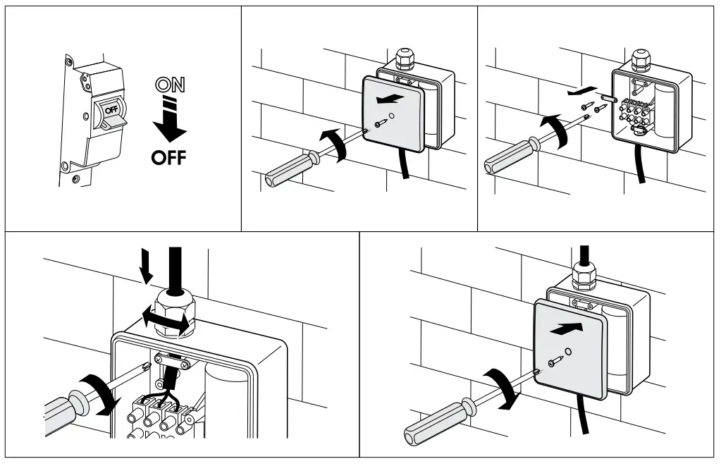
Axis-F, Tubo-M(Z), Tubo-MA(Z) fan connection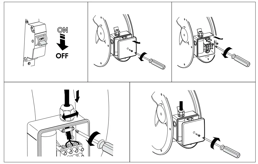
Tubo-F fan connection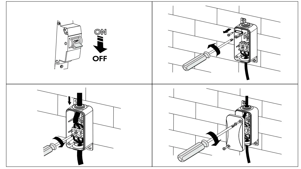
TECHNICAL MAINTENANCE
![]() DISCONNECT THE UNIT FROM POWER SUPPLY BEFORE ANY MAINTENANCE OPERATIONS!
DISCONNECT THE UNIT FROM POWER SUPPLY BEFORE ANY MAINTENANCE OPERATIONS!
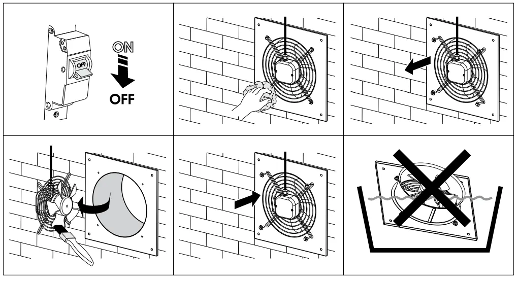
All the operations specific to the technical maintenance must be performed upon disconnecting the fan from power mains. The technical maintenance includes periodic cleaning of the fan surfaces from dust and dirt. To dust off the metal parts of the fan, use a dry soft brush or a stream of compressed air. Every 6 months clean the impeller with a warm detergent solution while avoiding water penetration onto the electric motor. Wipe the cleaned surfaces dry.
To carry out technical maintenance of the Axis-F, Tubo-M(Z), Tubo-MA(Z), Tubo-F fans, remove the fans from the duct by undoing the retaining bolts on the Axis-F units or disconnecting the mounting clamps on the Tubo-M(Z), Tubo-MA(Z) and Tubo-F units. To carry out work on the Axis-Q, Axis-QR, Axis-QA, Axis-QRA units, undo the bolt 4 and disconnect the grille and electric motor assembly from the casing
Axis-Q and Axis-QR technical maintenance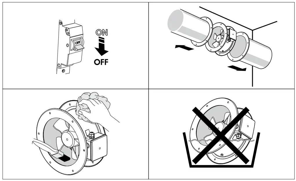 Axis-F technical maintenance
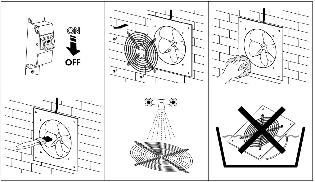
Axis-QA and Axis-QRA technical maintenance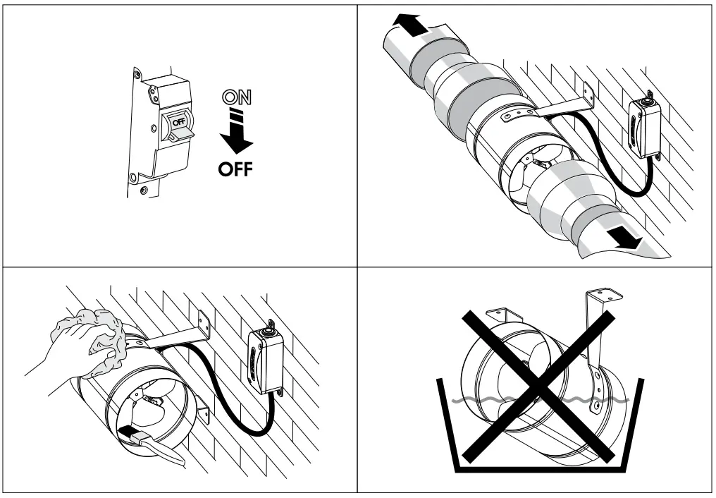
TROUBLESHOOTING
| PROBLEM | POSSIBLE REASONS | TROUBLESHOOTING |
|
The fan will not start on power-up. | No electric power. | Check the electrical connections and the power switch status. |
| Motor jamming. | Switch off the fan. Eliminate the cause for the impeller clogging. Switch the fan back on. | |
| The automatic breaker activates upon the unit power-up. | The automatic circuit breaker is triggered by abnormally high current consumption due to a short circuit. | Disconnect the fan from the power mains and contact the Seller. Do not switch on the fan again! |
| Low air flow. | Clogging of air ducts or other ventilation system elements due to contamination. Impeller contamination. Damaged air ducts. Closed air dampers. | Clean the air ducts and other ventilation system elements as well as the impeller. Check the air ducts for damage. Make sure that the air dampers and louvers are open. |
If the malfunction is too complex to be eliminated on the spot, contact the fan Seller.
STORAGE AND TRANSPORTATION REGULATIONS
- Store the unit in the manufacturer’s original packaging box in a dry closed ventilated premise with temperature range from +5 ˚C to +40 ˚C and relative humidity up to 70 %.
- Storage environment must not contain aggressive vapors and chemical mixtures provoking corrosion, insulation, and sealing deformation.
- Use suitable hoist machinery for handling and storage operations to prevent possible damage to the unit.
- Follow the handling requirements applicable for the particular type of cargo.
- The unit can be carried in the original packaging by any mode of transport provided proper protection against precipitation and mechanical The unit must be transported only in the working position.
- Avoid sharp blows, scratches, or rough handling during loading and unloading.
- Prior to the initial power-up after transportation at low temperatures, allow the unit to warm up at operating temperature for at least 3-4 hours.
MANUFACTURER’S WARRANTY
The product is in compliance with EU norms and standards on low voltage guidelines and electromagnetic compatibility. We hereby declare that the product complies with the provisions of Electromagnetic Compatibility (EMC) Directive 2014/30/EU of the European Parliament and of the Council, Low Voltage Directive (LVD) 2014/35/EU of the European Parliament and of the Council and CE-marking
Council Directive 93/68/EEC. This certificate is issued following test carried out on samples of the product referred to above. The manufacturer hereby warrants normal operation of the unit for 24 months after the retail sale date provided the user’s observance of the transportation, storage, installation, and operation regulations. Should any malfunctions occur in the course of the unit operation through the Manufacturer’s fault during the guaranteed period of operation, the user is entitled to get all the faults eliminated by the manufacturer by means of warranty repair at the factory free of charge. The warranty repair includes work specific to elimination of faults in the unit operation to ensure its intended use by the user within the guaranteed period of operation. The faults are eliminated by means of replacement or repair of the unit components or a specific part of such unit component.
The warranty repair does not include:
- routine technical maintenance
- unit installation/dismantling
- unit setup
To benefit from warranty repair, the user must provide the unit, the user’s manual with the purchase date stamp, and the payment paperwork certifying the purchase. The unit model must comply with the one stated in the user’s manual. Contact the Seller for warranty service.
The manufacturer’s warranty does not apply to the following cases:
- User’s failure to submit the unit with the entire delivery package as stated in the user’s manual including submission with missing component parts previously dismounted by the user.
- Mismatch of the unit model and the brand name with the information stated on the unit packaging and in the user’s manual.
- User’s failure to ensure timely technical maintenance of the unit.
- External damage to the unit casing (excluding external modifications as required for installation) and internal components caused by the user.
- Redesign or engineering changes to the unit.
- Replacement and use of any assemblies, parts and components not approved by the manufacturer.
- Unit misuse.
- Violation of the unit installation regulations by the user.
- Violation of the unit control regulations by the user.
- Unit connection to power mains with a voltage different from the one stated in the user’s manual.
- Unit breakdown due to voltage surges in power mains.
- Discretionary repair of the unit by the user.
- Unit repair by any persons without the manufacturer’s authorization.
- Expiration of the unit warranty period.
- Violation of the unit transportation regulations by the user.
- Violation of the unit storage regulations by the user.
- Wrongful actions against the unit committed by third parties.
- Unit breakdown due to circumstances of insuperable force (fire, flood, earthquake, war, hostilities of any kind, blockades).
- Missing seals if provided by the user’s manual.
- Failure to submit the user’s manual with the unit purchase date stamp.
- Missing payment paperwork certifying the unit purchase.
![]() FOLLOWING THE REGULATIONS STIPULATED HEREIN WILL ENSURE A LONG AND TROUBLE-FREE OPERATION OF THE UNIT.
FOLLOWING THE REGULATIONS STIPULATED HEREIN WILL ENSURE A LONG AND TROUBLE-FREE OPERATION OF THE UNIT.![]() USER’S WARRANTY CLAIMS SHALL BE SUBJECT TO REVIEW ONLY UPON PRESENTATION OF THE UNIT, THE PAYMENT DOCUMENT AND THE USER’S MANUAL WITH THE PURCHASE DATE STAMP.
USER’S WARRANTY CLAIMS SHALL BE SUBJECT TO REVIEW ONLY UPON PRESENTATION OF THE UNIT, THE PAYMENT DOCUMENT AND THE USER’S MANUAL WITH THE PURCHASE DATE STAMP.
CERTIFICATE OF ACCEPTANCE
| Unit Type | Industrial electric axial fans |
| Model | Axis-Q / Axis-QR / Axis-F / Axis-QA / Axis-QRA / Tubo-F / Tubo-M / Tubo-MA |
| Serial Number | |
| Manufacture Date | |
| Quality Inspector’s Stamp |
SELLER INFORMATION
| Seller | |
| Address | |
| Phone Number | |
| Purchase Date | |
| This is to certify acceptance of the complete unit delivery with the user’s manual. The warranty terms are acknowledged and accepted. | |
| Customer’s Signature | |
INSTALLATION CERTIFICATE
| The Axis-Q / Axis-QR / Axis-F / Axis-QA / Axis-QRA / Tubo-F / Tubo-M / Tubo-MA unit is installed pursuant to the requirements stated in the present user’s manual. | ||
| Company name | ||
| Address | ||
| Phone Number | ||
| Installation Technician’s Full Name | ||
| Installation Date: | Signature: | |
| The unit has been installed in accordance with the provisions of all the applicable local and national construction, electrical and technical codes and standards. The unit operates normally as intended by the manufacturer. | ||
| Signature: | ||
WARRANTY CARD
| Unit Type | Industrial electric axial fans |
| Model | Axis-Q/Axis-QR/Axis-F/Axis-QA/Axis-QRA/Tubo-F/Tubo-M/Tubo-MA |
| Serial Number | |
| Manufacture Date | |
| Purchase Date | |
| Warranty Period | |
| Seller |
 http://blaubergventilatoren.de
![]()


