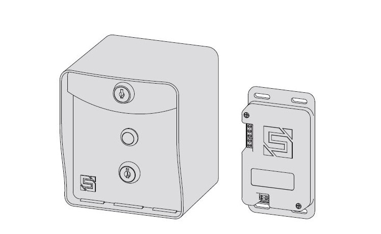
RIDGE RTE 14-RTE433 Request-to-Exit Station and Transceiver
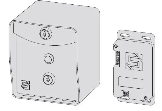
What’s what?
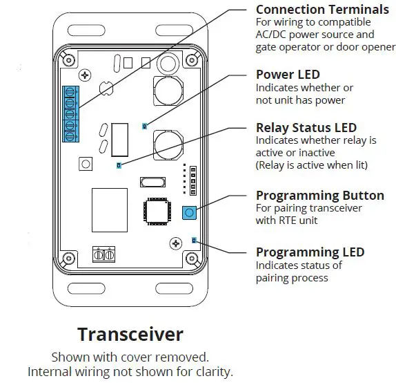
Important components labeled
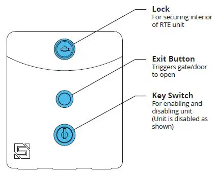
RTE Unit Front Panel (Front)
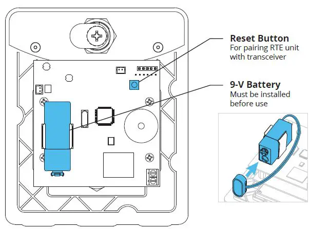
RTE Unit Front Panel (Back)
Internal wiring not shown for clarity.
Transceiver
Shown with cover removed.
Internal wiring not shown for clarity.
START HERE
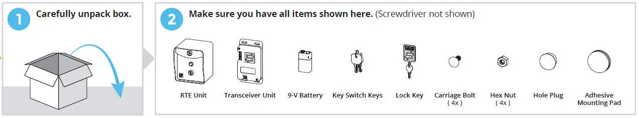
- Carefully unpack box.


- Make sure you have all items shown here. (Screwdriver not shown)
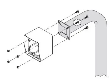
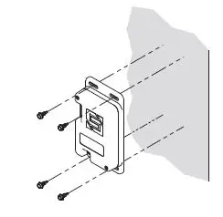
- Unlock and remove front panel of RTE unit; then using includedcarriage bolts and hex nuts, attach unit to pedestal as shown.

- Using Tek screws, zip ties, or included adhesive mounting pad, attach transceiver to inside wall or another surface of gate operator.

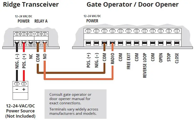
- Connect transceiver
Gate Operator Timer-to-Close
OFF Connect transceiver
Gate Operator Timer-to-Close
ON
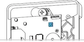
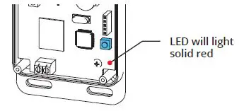
- Remove transceiver cover; then hold down Programming button on circuit board for 3 seconds and let go.

- Remove RTE unit front panel; then hold down Reset button on circuit board for 5 seconds and let go. (Make sure battery is connected)
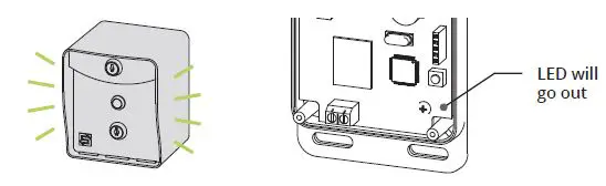
- While pairing, RTE unit will beep momentarily.
Once transceiver LED goes out, pairing is complete.
- Remove RTE unit front panel; then hold down Reset button on circuit board for 5 seconds and let go. (Make sure battery is connected)
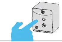
- Make sure gate/door path is clear; then press exit button on RTE unit and confirm gate/door opens. (If nothing happens, repeat Step 6)
 Connect transceiver
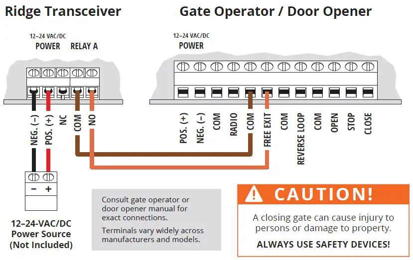
INSTALLATION COMPLETE
Your system is ready to use.
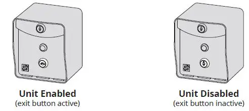
A: The RTE unit can be disabled and re-enabled at any time by taking the key switch keys and using the key switch located below the exit button.
B: Unit Reset Procedure
This procedure is used to reset unit to factory default settings.
Step 1 – Remove front panel of RTE unit.
Step 2 – Disconnect battery.
Step 3 – Press and hold Reset Button; reconnect battery; then release Reset Button. Unit will sound one (1) tone. Release Reset Button after you hear tone.
Step 4 – Press and release Reset Button; then reattach front panel onto RTE unit.
The unit is now reset to factory default settings.
NEED HELP
Call (972) 474-6390
Email [email protected]
We are available Mon–Fri / 8am–5pm Central
© 2021 Security Brands, Inc. All rights reserved.


