Microchip Technology PL360 G3-PLC Hybrid Profile
Product Introduction
The Microchip hardware platform proposal to run the G3-PLC Hybrid solution is based on a host controller, which runs the upper layers of the communication stack and the user application, and two modems, one for PLC and the other for RF. Taking this into account, Microchip proposes different hardware platforms where the examples can be run directly.
Product Hardware Platforms
The Microchip hardware platform proposal to run the G3-PLC Hybrid solution is based on a host controller, which runs the upper layers of the communication stack and the user application, and two modems, one for PLC and the other for RF. Taking this into account, Microchip proposes different hardware platforms where the examples can be run directly.
PL360G55Cx-EK + ATREB215-XPRO-A
The PL360G55Cx-EK uses the USB connector (J4) to communicate with a PC via console and the MikroBUS to communicate with the ATREB215-XPRO-A. The lines used in the connection between both boards are described in the following table and figure:
| Description | Power | GND | SPI | RF215 Reset | RF215 Interruption | LED1 | LED2 |
|---|---|---|---|---|---|---|---|
| mikroBUS Socket (PL360G55Cx-EK) | 7 (+3.3V) | 8 (GND) | 9 (GDN) | 3 (CS) | 15 (INT) | 11 (SDA) | 12 (SCL) |
| Xpained PRO Header (ATREB215-XPRO-A) | 20 (3V3) | 2 (GND) | 19 (GND) | 15 (SPI_SS_A) | N/A | N/A | N/A |
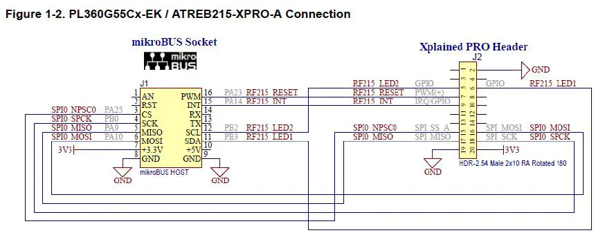
Figure 1-2 shows the connection of PL360G55Cx-EK and ATREB215-XPRO-A.

Product Usage Instructions
To use the PL360G55Cx-EK + ATREB215-XPRO-A hardware platform, follow these steps:
- Connect the PL360G55Cx-EK and ATREB215-XPRO-A using the lines specified in the table above and shown in Figure 1-2.
- Connect the PL360G55Cx-EK to a PC using the USB connector (J4) and open a console.
- Run the upper layers of the communication stack and the user application on the host controller.
- The two modems, one for PLC and the other for RF, will enable communication between the PL360G55Cx-EK and ATREB215-XPRO-A.
Introduction
The Microchip implementation of the G3-PLC firmware stack includes the G3-PLC Hybrid Profile based on the Hybrid G3-PLC and RF Profile Annex to the G3-PLC specification. This document explains how to start using the different resources, hardware and software, that Microchip provides related to the implementation of the G3-PLC Hybrid Profile. The Microchip G3-PLC Hybrid solution can be run in several hardware platforms, mainly composed by a PLC modem and a RF module. The PLC modems are based on the PL360 or PL460 devices to run the lower PLC layers of the stack. The RF module is based on the AT86RF215 device to run the lower RF layers of the stack. The upper layers of the communication stack run in the main microcontroller (host controller), SAMG55.
Hardware Platforms
The Microchip hardware platform proposal to run the G3-PLC Hybrid solution is based on a host controller, which runs the upper layers of the communication stack and the user application, and two modems, one for PLC and the other for RF. Taking this into account, Microchip proposes different hardware platforms where the examples can be run directly.
PL360G55Cx-EK + ATREB215-XPRO-A
This supported platform is composed of two different evaluation boards:
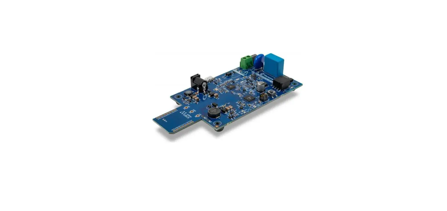
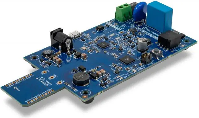
- The first board, a PL360G55Cx-EK (PL360G55CF-EK for CENELEC-A or FCC working bands or a PL360G55CB-EK for CENELEC-B working band), includes the host controller, a SAMG55J19, to run the application and the upper layers of the stack, and the PLC device, PL360, to run the PHY and MAC-RT layers for PLC communications.
- The second board is an ATREB215-XPRO-A with the AT86RF215 to run the PHY layer for the RF communications. The RF module is configured to run on the sub-GHz band.
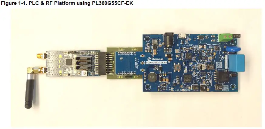
The PL360G55Cx-EK uses the USB connector (J4) to communicate with a PC via console and the MikroBUS to communicate with the ATREB215-XPRO-A. The lines used in the connection between both boards are described in the following table and figure:
| Description | mikroBUS Socket (PL360G55Cx-EK) | Xpained PRO Header (ATREB215-XPRO-A) |
| Power | 7 (+3.3V) | 20 (3V3) |
| GND | 8 (GND) | 2 (GND) |
| 9 (GDN) | 19 (GND) | |
| SPI | 3 (CS) | 15 (SPI_SS_A) |
| 4 (SCK) | 18 (SPI_SCK) | |
| 5 (MISO) | 17 (SPI_MISO) | |
| 6 (MOSI) | 16 ( SPI_MOSI) | |
| RF215 Reset | 16 (PWM) | 7 (PWM+) |
| RF215 Interruption | 15 (INT) | 9 (IRQ/GPIO) |
| LED1 | 11 (SDA) | 6 (GPIO2) |
| LED2 | 12 (SCL) | 5 (GPIO1) |
Important: To power up the ATREB215-XPRO-A board from a PL360G55Cx-EK board, it is required to mount a 0-Ohm resistor in the footprint close to the microbus pin of +3.3V (R21 in PL360G55CF-EK or R22 in PL360G55CB-EK).
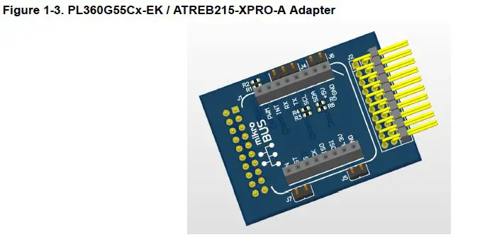
The design files of a customized adapter from mikroBus to Xplained PRO to connect PL360G55Cx-EK and ATREB215-XPRO-A boards is available from the Microchip website.
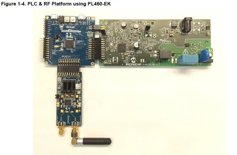
SAMG55 XPLAINED PRO + PL460-EK + ATREB215-XPRO-A
This supported platform is composed of three different evaluation boards:
- The first board, a SAMG55 EXPLAINED PRO evaluation kit, includes the host controller, a SAMG55J19, to run the application and the upper layers of the stack.
- The second board is the PL460-EK as the PLC module with a PL460 to run the PHY and MAC-RT layers for the PLC communications.
- The third board is an ATREB215-XPRO-A with the AT86RF215 to run the PHY layer for the RF module. The RF module is configured to run on the sub-GHz band.
The SAMG55 EXPLAINED PRO board uses the DEBUG USB connector to communicate with a PC via console. The SAMG55 EXPLAINED PRO board uses EXT3 to communicate with the ATREB215-XPRO-A board. The lines used in the connection between both boards are described in the following table:
| Description | Xpained PRO Header (ATREB215-XPRO-A) |
| 3V3 Power | 20 (3V3) |
| GND | 2 (GND) |
| 19 (GND) | |
| SPI | 15 (SPI_SS_A) |
| 18 (SPI_SCK) | |
| 17 (SPI_MISO) | |
| 16 ( SPI_MOSI) | |
| RF215 Reset | 7 (PWM+) |
| RF215 Interruption | 9 (IRQ/GPIO) |
| LED1 | 6 (GPIO2) |
| LED2 | 5 (GPIO1) |
The SAMG55 EXPLAINED PRO board uses EXT1 (with the Xplained Pro Power Header) to communicate with the PL460-EK. The lines used in the connection between both boards are described in the following table:
| Description | Xpained PRO Header (PL460-EK) |
| 3V3 Power | 20 (3V3) |
| GND | 2 (GND) |
| 19 (GND) | |
| SPI | 15 (SPI_SS_A) |
| 18 (SPI_SCK) | |
| 17 (SPI_MISO) | |
| 16 ( SPI_MOSI) | |
| PL460 Reset | 7 (PWM+) |
| PL460 Enable | 8 (PWM-) |
| PL460 Interruption | 9 (IRQ/GPIO) |
| PL460 NTHW0 Thermal warning | 10 (GPIO) |
| PL460 Standby | 11 (SDA) |
| PL460 Carrier detect | 12 (SCL) |
The SAMG55 EXPLAINED PRO board is powered by a USB connector, which also powers the ATREB215-XPRO-A board. The PL460-EK must be powered independently with its own 15V power supply.
Example Applications
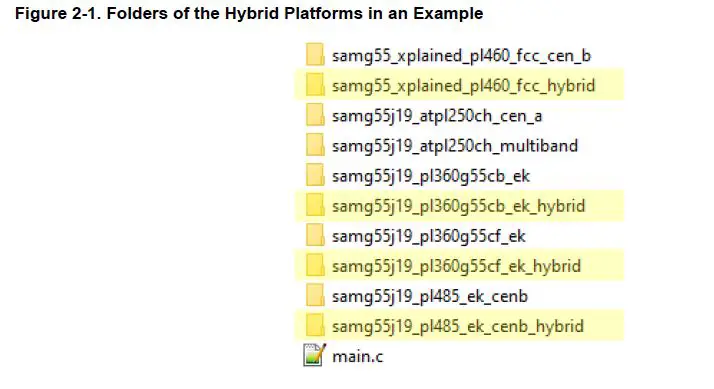
Microchip provides a firmware package including the G3-PLC communication stack, with examples and tools. The Microchip G3-PLC stack supports the G3-PLC Hybrid profile, and it includes several examples for using it in the supported hardware platforms. The projects for the hybrid platforms in the different examples are identified with the text “_hybrid” in the name of the folder:
DLMS G3-PLC Coordinator
The DLMS example for the G3-PLC coordinator implements a DLMS client that shows how the G3-PLC API along with an IPv6 stack can be used in a typical DLMS application. The coordinator performs a continuous DLMS data collection that generates data traffic in the G3-PLC network. Besides DLMS traffic, the application can be configured to generate ICMPv6 traffic sending PINGs to other nodes. The DLMS example for the coordinator periodically asks every device registered in the network for DLMS objects. A log can be checked using the console in the UART port. This example is located in the folder \thirdparty\g3\apps\dlms_app_coord\ of the firmware package:
Table 2-1. LEDs
| Description | Board | Indication | |
| Reception of message | RF | ATREB215-XPRO-A | LED2 |
| PLC | PL360G55Cx-EK | LED1 | |
| PL460-EK | — | ||
| Message transmitted | RF | ATREB215-XPRO-A | LED1 |
| PLC | PL360G55Cx-EK | D104/D110 | |
| PL460-EK | D4 | ||
DLMS G3-PLC Device
The DLMS example for a G3-PLC device implements a DLMS server that shows how the G3-PLC API along with an IPv6 stack can be used in a typical DLMS application.The device runs the DLMS server supporting some basic DLMS objects that can be consulted by a DLMS client. Besides DLMS traffic, the application can be configured to generate ICMPv6 traffic sending PINGs to other nodes. This application has to be combined with another board running the DLMS G3-PLC Coordinator to evaluate the complete evaluation of a full G3-PLC Network where typical DLMS traffic is interchanged. The DLMS example for the coordinator, provided by the Microchip G3-PLC stack, cycles a pooling asking every device registered in the network for DLMS objects. This example is located in the folder \thirdparty\g3\apps\dlms_app_dev\ of the firmware package:
Table 2-2. LEDs
| Description | Board | Indication | |
| Reception of message | RF | ATREB215-XPRO-A | LED2 |
| PLC | PL360G55Cx-EK | LED1 | |
| PL460-EK | — | ||
| Message transmitted | RF | ATREB215-XPRO-A | LED1 |
| PLC | PL360G55Cx-EK | D104/D110 | |
| PL460-EK | D4 | ||
ADP & MAC Serialization
The ADP and MAC serialization is an application example that brings access to the ADP, MAC and Coordinator API through a serialized interface attached to a serial connection. This application is useful for users who want to make an intensive test of the stack or want to run the upper layers in another CPU. The application interfaces with the G3-PLC stack at different levels. The user can make use of the ADP API (standard access) or access the MAC Wrapper API directly as a shortcut for some tests. Serialization is also available to the provided Coordinator module in case the user wants to control the Bootstrap phase on the Coordinator side. The example provided offers the serial interface configured through a certain UART or USB (depending on the platform) at 230400 bps by default. This example is located in the folder \thirdparty\g3\apps\adp_mac_serialized_app\ of the firmware package:
Table 2-3. Serial Ports
| Board | Description | Serial Port | Baudrate |
| SAMG55 Xplained Pro | ADP & MAC serial interface | Target USB | 240300 |
| Console | Debug USB | 115200 | |
| PL360G55Cx-EK | ADP & MAC serial interface | USB | 240300 |
Table 2-4. LEDs
| Description | Board | LED | |
| Reception of message | RF | ATREB215-XPRO-A | LED2 |
| PLC | PL360G55Cx-EK | LED1 | |
| PL460-EK | — | ||
| Message transmitted | RF | ATREB215-XPRO-A | LED1 |
| PLC | PL360G55Cx-EK | D104/D110 | |
| PL460-EK | D4 |
PHY Sniffer
The PHY Sniffer is an application example that uses the PHY layer to monitor G3-PLC frames in the network and send them via USI serialization. The Hybrid Sniffer PC tool is also provided to interface with the board and interpret the frames. This example requires only one board and a G3-PLC network to be monitored. The example provided offers the serial interface configured through a certain UART or USB (depending on the platform) at 230400 bps by default. This example is located in the folder \thirdparty\g3\phy\atpl360\apps\phy_sniffer_hybrid_tool\ of the firmware package:
Table 2-5. LEDs
| Description | Board | LED | |
| Reception of message | RF | ATREB215-XPRO-A | LED2 |
| PLC | PL360G55Cx-EK | LED1 | |
| PL460-EK | — | ||
Revision History
Rev A – 04/2022
- Document Initial release
The Microchip Website
Microchip provides online support via our website at www.microchip.com/. This website is used to make files and information easily available to customers. Some of the content available includes:
- Product Support – Datasheets and errata, application notes and sample programs, design resources, user’s guides and hardware support documents, latest software releases and archived software
- General Technical Support – Frequently Asked Questions (FAQs), technical support requests, online discussion groups, Microchip design partner program member listing
- Business of Microchip – Product selector and ordering guides, latest Microchip press releases, a listing of seminars and events, listings of Microchip sales offices, distributors and factory representatives
Product Change Notification Service
Microchip’s product change notification service helps keep customers current on Microchip products. Subscribers will receive email notifications whenever there are changes, updates, revisions or errata related to a specified product family or development tool of interest. To register, go to www.microchip.com/pcn and follow the registration instructions.
Customer Support
Users of Microchip products can receive assistance through several channels:
- Distributor or Representative
- Local Sales Office
- Embedded Solutions Engineer (ESE)
- Technical Support
Customers should contact their distributor, representative or ESE for support. Local sales offices are also available to help customers. A listing of sales offices and locations is included in this document. Technical support is available through the website at: www.microchip.com/support
Microchip Devises Code Protection Feature
Note the following details of the code protection feature on Microchip products:
- Microchip products meet the specifications contained in their particular Microchip Data Sheet.
- Microchip believes that its family of products is secure when used in the intended manner, within operating specifications, and under normal conditions.
- Microchip values and aggressively protects its intellectual property rights. Attempts to breach the code protection features of Microchip product is strictly prohibited and may violate the Digital Millennium Copyright Act.
- Neither Microchip nor any other semiconductor manufacturer can guarantee the security of its code. Code protection does not mean that we are guaranteeing the product is “unbreakable”. Code protection is constantly evolving. Microchip is committed to continuously improving the code protection features of our products.
Legal Notice
This publication and the information herein may be used only with Microchip products, including to design, test, and integrate Microchip products with your application. Use of this information in any other manner violates these terms. Information regarding device applications is provided only for your convenience and may be superseded
by updates. It is your responsibility to ensure that your application meets with your specifications. Contact your local Microchip sales office for additional support or, obtain additional support at www.microchip.com/en-us/support/design-help/client-support-services.
THIS INFORMATION IS PROVIDED BY MICROCHIP “AS IS”. MICROCHIP MAKES NO REPRESENTATIONS OR WARRANTIES OF ANY KIND WHETHER EXPRESS OR IMPLIED, WRITTEN OR ORAL, STATUTORY OR OTHERWISE, RELATED TO THE INFORMATION INCLUDING BUT NOT LIMITED TO ANY IMPLIED WARRANTIES OF NON-INFRINGEMENT, MERCHANTABILITY, AND FITNESS FOR A PARTICULAR PURPOSE, OR WARRANTIES RELATED TO ITS CONDITION, QUALITY, OR PERFORMANCE. IN NO EVENT WILL MICROCHIP BE LIABLE FOR ANY INDIRECT, SPECIAL, PUNITIVE, INCIDENTAL, OR CONSEQUENTIAL LOSS, DAMAGE, COST, OR EXPENSE OF ANY KIND WHATSOEVER RELATED TO THE INFORMATION OR ITS USE, HOWEVER, CAUSED, EVEN IF MICROCHIP HAS BEEN ADVISED OF THE POSSIBILITY OR THE DAMAGES ARE FORESEEABLE? TO THE FULLEST EXTENT ALLOWED BY LAW, MICROCHIP’S TOTAL LIABILITY ON ALL CLAIMS IN ANY WAY RELATED TO THE INFORMATION OR ITS USE WILL NOT EXCEED THE NUMBER OF FEES, IF ANY, THAT YOU HAVE PAID DIRECTLY TO MICROCHIP FOR THE INFORMATION.
Use of Microchip devices in life support and/or safety applications is entirely at the buyer’s risk, and the buyer agrees to defend, indemnify and hold harmless Microchip from any and all damages, claims, suits, or expenses resulting from such use. No licenses are conveyed, implicitly or otherwise, under any Microchip intellectual property rights unless otherwise stated.
Trademarks
The Microchip name and logo, the Microchip logo, Adaptec, AnyRate, AVR, AVR logo, AVR Freaks, BesTime, BitCloud, CryptoMemory, CryptoRF, dsPIC, flexPWR, HELDO, IGLOO, JukeBlox, KeeLoq, Kleer, LANCheck, LinkMD, maXStylus, maXTouch, MediaLB, megaAVR, Microsemi, Microsemi logo, MOST, MOST logo, MPLAB, OptoLyzer, PIC, picoPower, PICSTART, PIC32 logo, PolarFire, Prochip Designer, QTouch, SAM-BA, SenGenuity, SpyNIC, SST, SST Logo, SuperFlash, Symmetricom, SyncServer, Tachyon, TimeSource, tinyAVR, UNI/O, Vectron, and XMEGA are registered trademarks of Microchip Technology Incorporated in the U.S.A. and other countries. AgileSwitch, APT, ClockWorks, The Embedded Control Solutions Company, EtherSynch, Flashtec, Hyper Speed Control, HyperLight Load, IntelliMOS, Libero, motor bench, mTouch, Powermite 3, Precision Edge, ProASIC, ProASIC Plus, ProASIC Plus logo, Quiet- Wire, SmartFusion, SyncWorld, Temux, TimeCesium, TimeHub, TimePictra, TimeProvider, TrueTime, WinPath, and ZL are registered trademarks of Microchip Technology Incorporated in the U.S.A. Adjacent Key Suppression, AKS, Analog-for-the-Digital Age, Any Capacitor, AnyIn, AnyOut, Augmented Switching, BlueSky, BodyCom, CodeGuard, CryptoAuthentication, CryptoAutomotive, CryptoCompanion, CryptoController, dsPICDEM, dsPICDEM.net, Dynamic Average Matching, DAM, ECAN, Espresso T1S, EtherGREEN, GridTime, IdealBridge, In-Circuit Serial Programming, ICSP, INICnet, Intelligent Paralleling, Inter-Chip Connectivity, JitterBlocker, Knob-on-Display, maxCrypto, maxView, memBrain, Mindi, MiWi, MPASM, MPF, MPLAB Certified logo, MPLIB, MPLINK, MultiTRAK, NetDetach, NVM Express, NVMe, Omniscient Code Generation, PICDEM, PICDEM.net, PICkit, PICtail, PowerSmart, PureSilicon, QMatrix, REAL ICE, Ripple Blocker, RTAX, RTG4, SAMICE, Serial Quad I/O, simpleMAP, SimpliPHY, SmartBuffer, SmartHLS, SMART-I.S., storClad, SQI, SuperSwitcher, SuperSwitcher II, Switchtec, SynchroPHY, Total Endurance, TSHARC, USBCheck, VariSense, VectorBlox, VeriPHY, ViewSpan, WiperLock, XpressConnect, and ZENA are trademarks of Microchip Technology Incorporated in the U.S.A. and other countries.
SQTP is a service mark of Microchip Technology Incorporated in the U.S.A. The Adaptec logo, Frequency on Demand, Silicon Storage Technology, Symmcom, and Trusted Time are registered trademarks of Microchip Technology Inc. in other countries. GestIC is a registered trademark of Microchip Technology Germany II GmbH & Co. KG, a subsidiary of Microchip Technology Inc., in other countries. All other trademarks mentioned herein are the property of their respective companies.
© 2022, Microchip Technology Incorporated and its subsidiaries. All Rights Reserved. ISBN: 978-1-6683-0108-1
Quality Management System
For information regarding Microchip’s Quality Management Systems, please visit www.microchip.com/quality.
Worldwide Sales and Service
| AMERICAS | ASIA/PACIFIC | ASIA/PACIFIC | EUROPE |
| Corporate Office 2355 West Chandler Blvd. Chandler, AZ 85224-6199 Tel: 480-792-7200 Fax: 480-792-7277 Technical Support: www.microchip.com/support Web Address: www.microchip.com Atlanta Duluth, GA Tel: 678-957-9614 Fax: 678-957-1455 Austin, TX Tel: 512-257-3370 Boston Westborough, MA Tel: 774-760-0087 Fax: 774-760-0088 Chicago Itasca, IL Tel: 630-285-0071 Fax: 630-285-0075 Dallas Addison, TX Tel: 972-818-7423 Fax: 972-818-2924 Detroit Novi, MI Tel: 248-848-4000 Houston, TX Tel: 281-894-5983 Indianapolis Noblesville, IN Tel: 317-773-8323 Fax: 317-773-5453 Tel: 317-536-2380 Los Angeles Mission Viejo, CA Tel: 949-462-9523 Fax: 949-462-9608 Tel: 951-273-7800 Raleigh, NC Tel: 919-844-7510 New York, NY Tel: 631-435-6000 San Jose, CA Tel: 408-735-9110 Tel: 408-436-4270 Canada – Toronto Tel: 905-695-1980 Fax: 905-695-2078 | Australia – Sydney Tel: 61-2-9868-6733 China – Beijing Tel: 86-10-8569-7000 China – Chengdu Tel: 86-28-8665-5511 China – Chongqing Tel: 86-23-8980-9588 China – Dongguan Tel: 86-769-8702-9880 China – Guangzhou Tel: 86-20-8755-8029 China – Hangzhou Tel: 86-571-8792-8115 China – Hong Kong SAR Tel: 852-2943-5100 China – Nanjing Tel: 86-25-8473-2460 China – Qingdao Tel: 86-532-8502-7355 China – Shanghai Tel: 86-21-3326-8000 China – Shenyang Tel: 86-24-2334-2829 China – Shenzhen Tel: 86-755-8864-2200 China – Suzhou Tel: 86-186-6233-1526 China – Wuhan Tel: 86-27-5980-5300 China – Xian Tel: 86-29-8833-7252 China – Xiamen Tel: 86-592-2388138 China – Zhuhai Tel: 86-756-3210040 | India – Bangalore Tel: 91-80-3090-4444 India – New Delhi Tel: 91-11-4160-8631 India – Pune Tel: 91-20-4121-0141 Japan – Osaka Tel: 81-6-6152-7160 Japan – Tokyo Tel: 81-3-6880- 3770 Korea – Daegu Tel: 82-53-744-4301 Korea – Seoul Tel: 82-2-554-7200 Malaysia – Kuala Lumpur Tel: 60-3-7651-7906 Malaysia – Penang Tel: 60-4-227-8870 Philippines – Manila Tel: 63-2-634-9065 Singapore Tel: 65-6334-8870 Taiwan – Hsin Chu Tel: 886-3-577-8366 Taiwan – Kaohsiung Tel: 886-7-213-7830 Taiwan – Taipei Tel: 886-2-2508-8600 Thailand – Bangkok Tel: 66-2-694-1351 Vietnam – Ho Chi Minh Tel: 84-28-5448-2100 | Austria – Wels Tel: 43-7242-2244-39 Fax: 43-7242-2244-393 Denmark – Copenhagen Tel: 45-4485-5910 Fax: 45-4485-2829 Finland – Espoo Tel: 358-9-4520-820 France – Paris Tel: 33-1-69-53-63-20 Fax: 33-1-69-30-90-79 Germany – Garching Tel: 49-8931-9700 Germany – Haan Tel: 49-2129-3766400 Germany – Heilbronn Tel: 49-7131-72400 Germany – Karlsruhe Tel: 49-721-625370 Germany – Munich Tel: 49-89-627-144-0 Fax: 49-89-627-144-44 Germany – Rosenheim Tel: 49-8031-354-560 Israel – Ra’anana Tel: 972-9-744-7705 Italy – Milan Tel: 39-0331-742611 Fax: 39-0331-466781 Italy – Padova Tel: 39-049-7625286 Netherlands – Drunen Tel: 31-416-690399 Fax: 31-416-690340 Norway – Trondheim Tel: 47-72884388 Poland – Warsaw Tel: 48-22-3325737 Romania – Bucharest Tel: 40-21-407-87-50 Spain – Madrid Tel: 34-91-708-08-90 Fax: 34-91-708-08-91 Sweden – Gothenburg Tel: 46-31-704-60-40 Sweden – Stockholm Tel: 46-8-5090-4654 UK – Wokingham Tel: 44-118-921-5800 Fax: 44-118-921-5820 |
© 2022 Microchip Technology Inc. and its subsidiaries.


