![]() HYBRID-P MU421 Control Panel for Hybrid Units
HYBRID-P MU421 Control Panel for Hybrid Units
User Manual 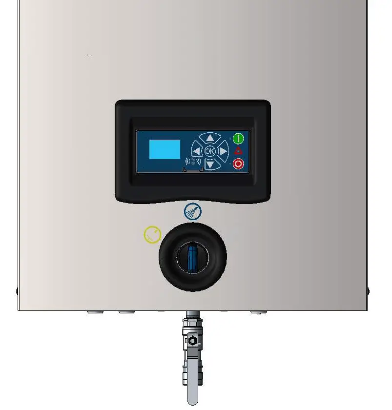
Description
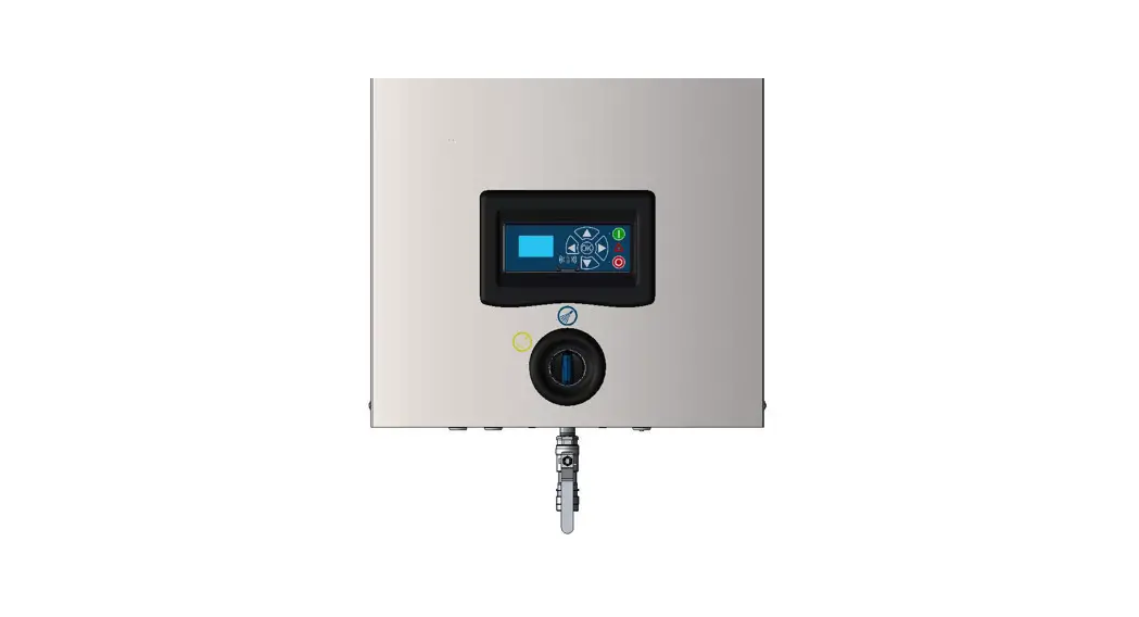
This software manual describes the operation of the control panel of the advanced Single Booster unit (SB and SBHL).
The advanced SB unit is operated via the control panel (see below illustration).
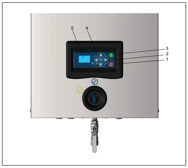
- OFF
Button (1) switches OFF the unit. - ON/STANDBY
Button (2) switches ON the unit. - ERROR
Error light indicator (3). - NAVIGATION BUTTONS
The four ”arrow” navigation buttons (4) are used for navigation in the display menu. Pressing the ”OK” button activates the menu and confirms any activity displayed. - DISPLAY
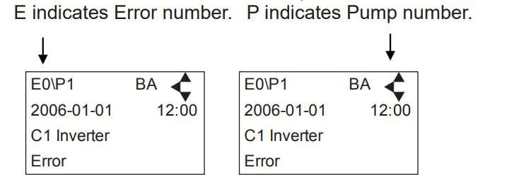
Display layout
Example: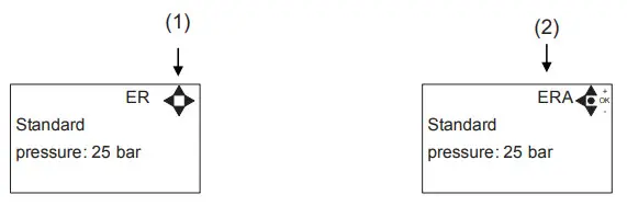
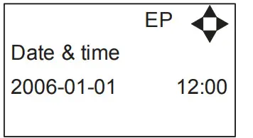
- When switched on the display will show an arrow symbol in the top right corner equivalent to the active navigation buttons on the control board.
The arrows illustrate that it is possible to scroll up and down between the menus. Scrolling to the right makes it possible to enter a value. Set the value scrolling up (+) or down (-) to set the value higher or lower accordingly. Confirm by pressing ok. - A letter combination for easy reference in connection with service work will appear in the top right corner of the display.
Modes
Power On
The very first time the unit is switched on, we recommend setting the date and time in the Setup menu, settings, and displaying EP. If the date and time are not set, the date and time will count from the pre-set default date and time.
Set date and time using navigation buttons.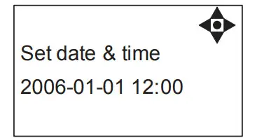 Confirm by pressing an OK button.
Standby
The start-up display will look like the one below.  Display for SB model with High- and Low pressure – Select either HP or LP using arrows up & down.
Run Mode
Single Booster with high and low pressure
The following screen displays will appear when the unit is in Run Mode.
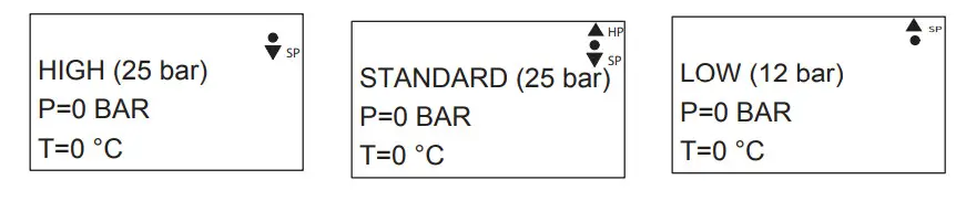
Screen display for High-pressure unit in Run Mode.
Scroll down to return to STANDARD pressure.
Screen display STANDARD pressure.
Scroll up to choose HP and scroll down to choose LP.
Screen display for Low-Pressure unit in Run Mode.
Scroll up to return to STANDARD pressure.
Please note that you will remain in HIGH or LOW-pressure Run Mode until otherwise is selected.
Power Off 
When the unit is off the display will only show a small dot in the top right corner.
In Off mode, it is possible to access all menus without the pump running by pressing the OK button on the panel.
Dot is equivalent to the OK confirm button on the panel.
Error/Warning

In case of an error, “ ERROR” will appear on the display screen.
Press the OFF button to switch of unit.
If the error remains when the unit is switched ON again, please Press the right arrow to see the current error.
In case of a warning, “WARNING” will appear on the display screen. When a warning is detected the machine will either stop or run with limited performance until the cause of the warning has been improved (eg. inlet pressure).
To see further error/warning list and possible causes and remedies go to section 5.2.
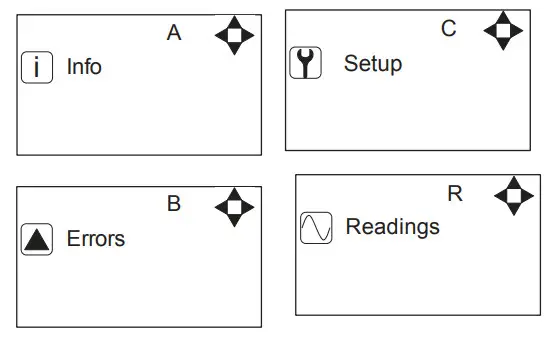
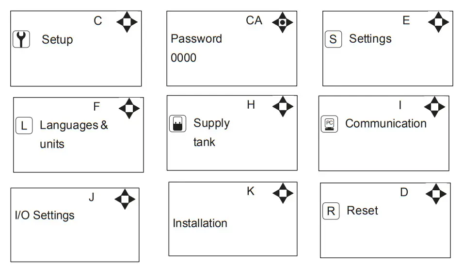
The control panel contains the below main menu screen displays.
Scroll between the menus using the navigation buttons.
Each main menu contains submenus which will be described subsequently.
| Info (A) 1 Σ Counters total (AA) 2 Σ Counters trip (AB) 3 Service center(AD) 4 Machine info (AE) Errors (B) Setup (C) (default password 6802) 1 Password (CA) 2 Settings (E) Post run time (ED) Dry run level (EE) Standard pressure (ER) High pressure (EA) Low pressure (EB) Startup method (EY) Pressure start level(EX) Startup delay (EW) Quick Start level (EC) Auto off delay (EZ) Accelleration time (EU) Date & Time (EP) Service text (EJ) Inverter power (EO) Backlight intensity (EI) Display contrast (EV) User password (EL) Standard settings (EK) 3 Languages & units (F) Language (FA) Units (FB) 4 Supply Tank (H) Tank control OFF (HA) LLA Detect Delay (HB) 5 Communication (I) Firmware Upgrade by cable (IC) Firmware Upgrade by infrared (ID) 6. I/O Settings (J) Output 1 (JA) Output 2 (JB) Input (JC) 7. Installation (K) Install password (KA) 8 Resets (D) Reset trip counters(DA) | Readings (R) Pump state (RA) Outlet pres. (RB) Water temp (RC) Supply pressure (RD) Flow Status (RF) |
Please note that the Info menu is only for display – all data must be typed in via the setup menu!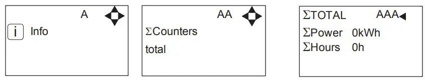
Displays accumulated consumption of power and operation hours.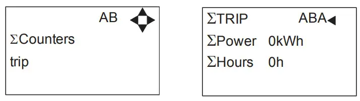
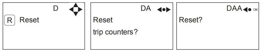
Displays accumulated consumption of power and operation hours.To reset the trip counter go to the setup menu. 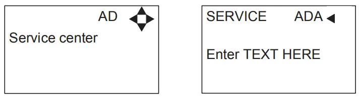
Displays name and tel. no. of a service technician. 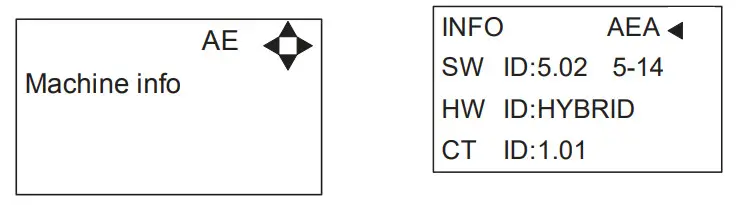
This display view is only ment as an example, SW ID and CT ID show the current SW version.
Displays Software version and Pump size, machine configuration, and inverter software version.
Example of Error log screen display:
All error occurrences will be stamped with the date and time.
The error log stores up to 1000 occurrences. When max. memory is reached, and the errors will be deleted according to the”First in” First out” principle.
Error List
| Error | Cause | Remedy |
| C1 Inverter Error | 1. Frequency inverter in error state | 1. Switch off the power on the service switch. Wait 180 sec. Switch on the unit again. If error still occurs, please contact your local service technician. |
| C2 Low Supply Pressure | 1. Insufficient water supply | 1. Secure sufficient water supply pressure. 2. Check inlet filter for impurities/rinse filter 3. Contact your local service technician. |
| C3 High Water Temp. | 1. Water pump top temperature is above 80° 2. Water consumption is too low (pump column has been overheated) | 1. Lower the inlet water temp. (max 70°C) 2. Secure sufficient water consumption 3. Contact your local service technician. |
| C4 High Motor Temp. | 1. Insufficient cooling of motor 2. The ambient temperature is above 40° | 1. Secure that all air channels are open and not blocked by impurities 2. Lower ambient temperature |
| C5 High Supply Temp. | 1. Water inlet temperature is above 70° | 1. Lower the water temp. (max 70°C) 2. Contact your local service technician. |
| C6 Low Sensor Supply Voltage | 1. Voltage supply for sensors too low | 1. Press the “off’ button 2. If an error reoccurs, contact your local service technician. |
| C7 No Response Error | 1. No communication between display and control board | 1. Contact your local service technician. |
| C8 Low Tank Level | 1. Insufficient water supply 2. Water supply valve not open | 1. Check the correct water supply 2. Secure sufficient air supply to the valve 3. Contact your local service technician. |
| C9 High Tank Level | 1. Water supply valve not closed | 1. Secure sufficient air supply to the valve. 2. Contact your local service technician. |
| C11 Warning Cri. Inlet press. | 1. Insufficient water supply 2. Booster will return to standby mode after 20 sec. If this error occurs 3 times within 20 min. Error C2 occurs. | 1. Secure sufficient water supply or reduce consumption 2. Check inlet filter for impurities/rinse filter 3. Contact your local service technician. |
| C13 Warning Low inlet press. | 1. Insufficient water supply. The machine will keep on working as always, but the maximum speed of the pump will be reduced until sufficient inlet pressure is present | 1. Secure sufficient water supply or reduce consumption 2. Check melt filter for impurities/Rinse filter |
| C14 Warning leakage start | 1. Booster start condition changed to flow, due to leakage in pipe | 1. Check for leakage in pipe system. 2. Press “off’ button 3. If an error reoccurs, contact your local service technician. |
| C20 Low Sensor Signal P-Pump- top | 1. Pressure signal from pump top sensor, out of range | 1. Press the “off’ button 2. If an error reoccurs, contact your local service technician. |
| C21 Low Sensor Signal T-Pump- top | 1. Temperature signal from pump top, sensor, out of range | 1. Press the “off’ button 2. If an error reoccurs, contact your local service technician. |
| C22 Low Sensor Signal P-Inlet | 1. Pressure signal form inlet sensor, out of range | 1. Press the “off’ button 2. If an error reoccurs, contact your local service technician. |
| C23 Low Sensor Signal T-Inlet | 1. Temperature signal from inlet sensor, out of range | 1. Press the “off’ button 2. If an error reoccurs, contact your local service technician. |
| C24 Low Sensor Signal block | 1. Signal from block sensor, out of range | 1. Press the “off’ button 2. If an error reoccurs, contact your local service technician. |
| C25 Low Sensor Signal flow | 1. Signal from flow sensor, out of range | 1. Press the “off’ button 2. If an error reoccurs, contact your local service technician. |
| C30 High Sensor Signal P-Pump- top | 1. Pressure signal from pump top sensor, out of range | 1. Press the “off’ button 2. If an error reoccurs, contact your local service technician. |
| C31 High Sensor Signal T-Pump- top | 1. Temperature signal from pump top sensor, out of range | 1. Press the “off’ button 2. If an error reoccurs, contact your local service technician. |
| C32 High Sensor Signal P-Inlet | 1. Pressure signal from inlet sensor, out of range | 1. Press the “off’ button 2. If an error reoccurs, contact your local service technician. |
| C33 High Sensor Signal T-Inlet | 1. Temperature signal from inlet sensor, out of range | 1. Press the “off’ button 2. If an error reoccurs, contact your local service technician. |
| C34 High Sensor Signal block | 1. Signal from block sensor, out of range | 1. Press the “off’ button 2. If an error reoccurs, contact your local service technician. |
| C35 High Sensor Signal flow | 1. Signal from flow sensor, out of range | 1. Press the “off’ button 2. If an error reoccurs, contact your local service technician. |
| C40 Sensor Load Pump top Sensor | 1. Supply voltage for pump top sensor too low. 2. Pump top sensor using too much current | 1. Press the “off’ button 2. If an error reoccurs, contact your local service technician. |
| C41 Sensor Load Inlet sensor | 1. Supply voltage for inlet sensor too low 2. Inlet sensor using too much current | 1. Press “off’ button 2. If an error reoccurs, contact your local service technician. |
| C42 Sensor Load Block sensor | 1. Supply voltage for block sensor too low 2. Block sensor using too much current | 1. Press the “off’ button 2. If an error reoccurs, contact your local service technician. |
| C43 Sensor Load Flow sensor | 1. Supply voltage for flow sensor too low 2. Flow sensor using too much current | 1. Press “off’ button 2. If an error reoccurs, contact your local service technician. |
| C45 Inverter Module temp. | 1. Water consumption too high 2. Ambient temperature too high” | 1. Lower the load for the inverter 2. Lower the ambient temperature” |
| C46 Inverter Board temp.” | 1. Water consumption too high 2. Ambient temperature too high 3. Load at Board high” | 1. Lower the load for the inverter 2. Lower the ambient temperature 3. lower the load at the board” |
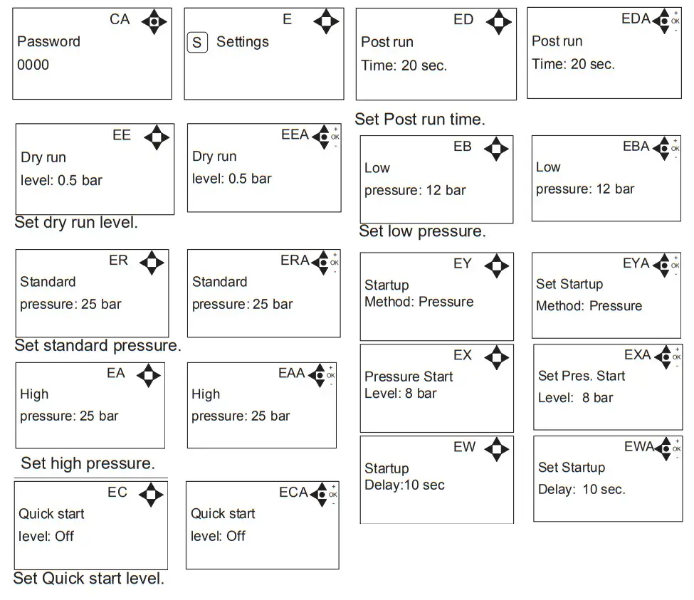
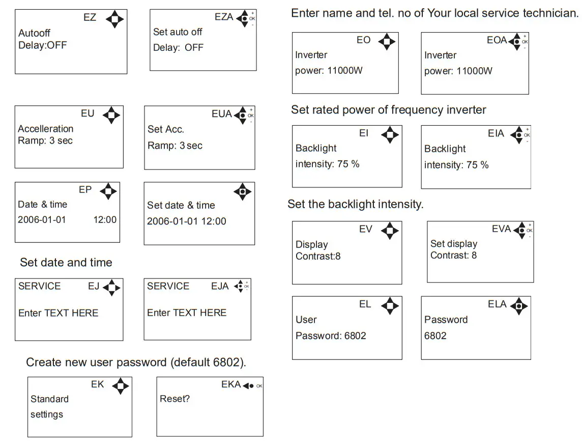
Content of the Setup sub-menu Settings
Password Note: The default user password is 6802. Enter the settings menu to change the default password. To avoid unintended access to the system your local service technician. can insert a blocking preventing access to the password-controlled menus.
Submenu Language & Units
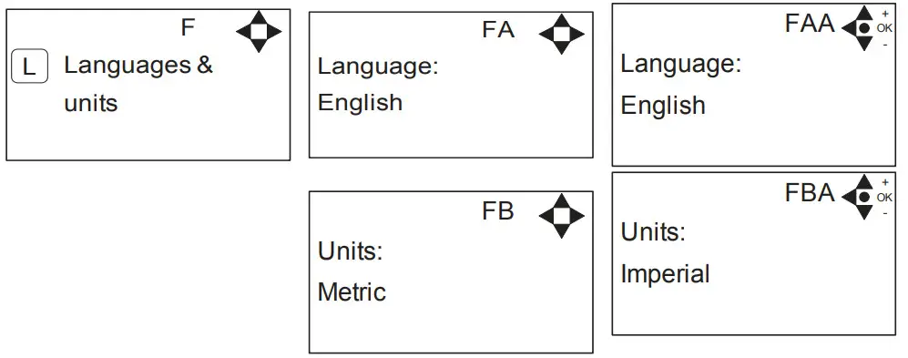
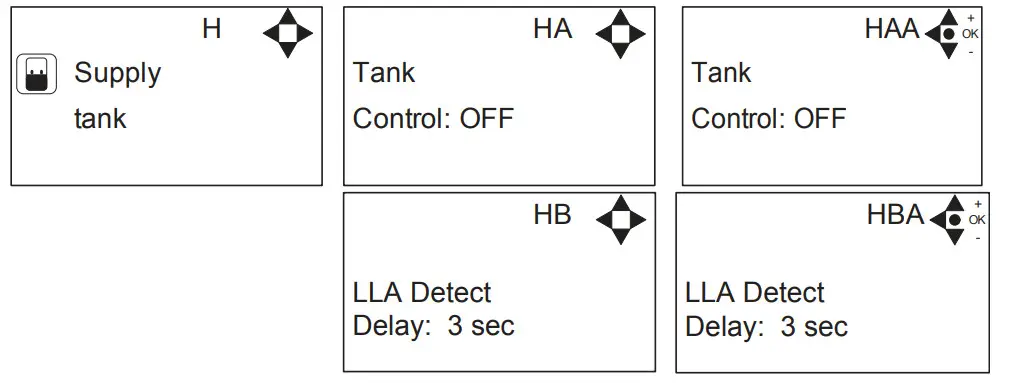
Submenu Supply tank
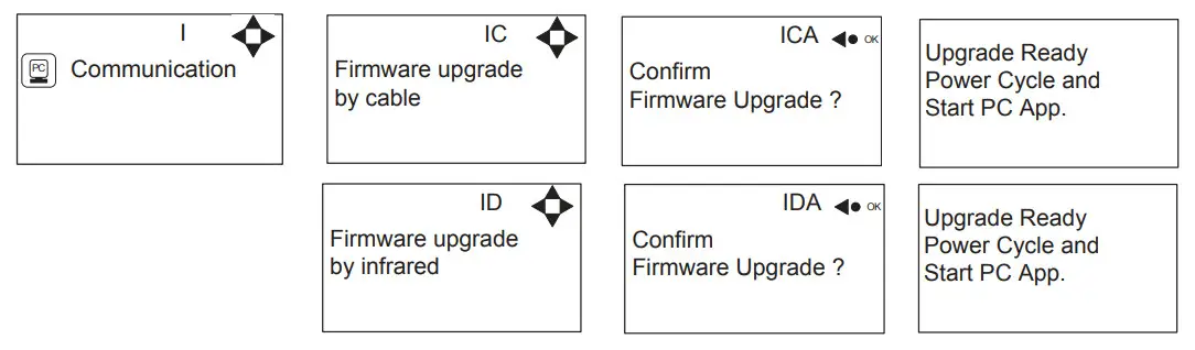
Submenu Communication
Submenu I/O Settings
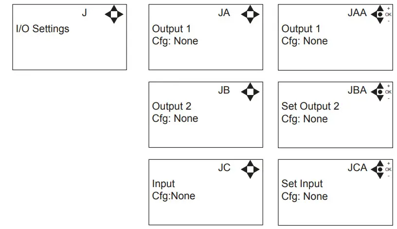
Output 1 options:
- None – No function
- Error – Active if an error are detected
- Run/Stop – Active if a booster is running and not active when it is stopped.
- Standby /off – active if a booster is running or in standby.
Output 2 options:
- None – No function
- Delay start – Gives a signal at this port, before starting the pump.
The length of the delay is set in the settings menu, startup delay.
This function could for instance be used to secure the start up of pressure pump before starting the unit.
Input
- None – No function
- Release – unit unable to start before this signal is present.
- Setpoint – Output pressure is controlled by an external voltage source.
- Chem. Low – Low levels in chemistry can
Submenu Installation
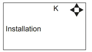
* For the use of authorized Your local service technician only.
Submenu Reset
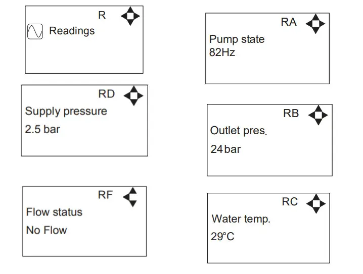
Content of Readings
Upgrade Firmware
Upgrading from software 5.02 or higher.
Upgrade display using USB Cable
- Connect the USB cable (Item No. 110007887) to the PC USB port (Remove other USB cables connected to PC)
- Connect Display cable to USB cable
- In the menu go to, Setup->” password”->Communication-> Firmware upgrade by cable- >Confirm Firmware upgrade and press “OK”
- The display should now be looking like this:

- Disconnect the display from usb cable and connect it again (Power cycle)
- Make sure the Green “ON” led and the red “OFF” led at the display is both on, display is blank
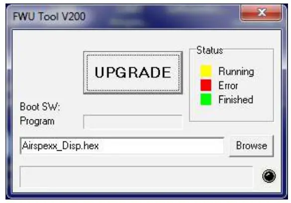
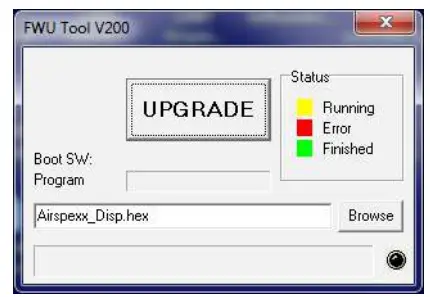
- Startup PC program FWU200.exe (can be downloaded from Nilfisk Food website)
- A window should be looking like this

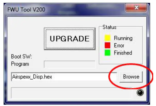
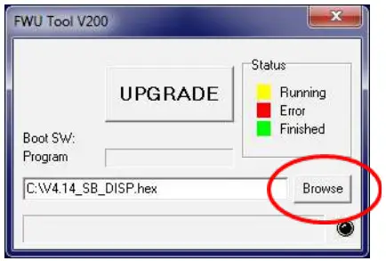
- Press the”Browse” button

- Select the file you will use for the upgrade. Software Files can be downloaded from the Nilfisk Food website. The name of the file should end with “.hex”. Ex V4.14_SB_DISP.hex
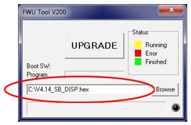
- When the file is located press “Open” in the browser window
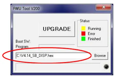
- The file name will now be written in the file text line

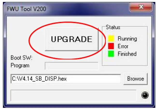
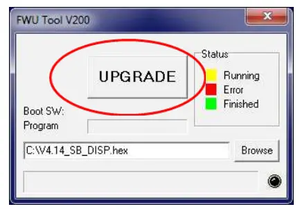
- Press UPGRADE button in FWU 200 tool

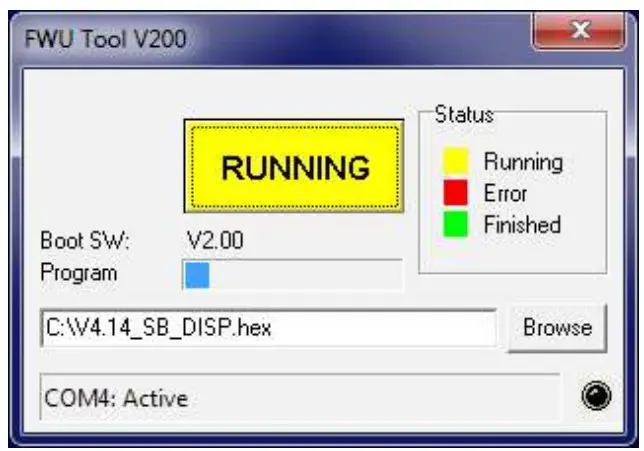
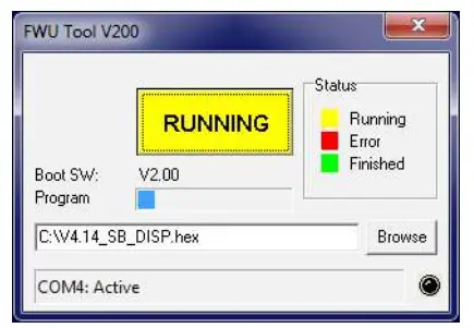
- After a short while the FWU tool should start upgrading, the upgrade button should turn Yellow and change to “RUNNING”

- The progress bar “Program” must go to the end before the upgrade is complete (less than 1 minute)
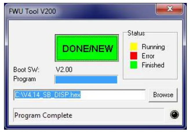
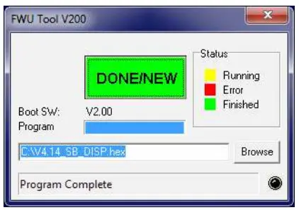
- When the upgrade is complete the FWU tool should be looking like this, Button turns Green and text changes to “DONE/NEW”

- Now the display is upgraded
- To verify the software version in the display, in the menu go to, Info->Machine info
- Here you will find the display software version and the control software version. SW ID “Display software”, HW ID “type of device”, CT ID Controller board software(if the display is not connected to a control board, control software will be 0/300)
Upgrade display using IrDA Cable
- Connect power to equipment
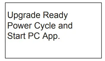
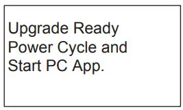
- In the menu go to, Setup->” password”->Communication-> Firmware upgrade by Infrared- >Confirm Firmware upgrade and press “OK”
- The display should now be looking like this: Upgrade Ready Power Cycle and Start PC App.

- Turn Off the equipment and turn it on again (Power cycle)
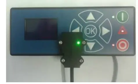
- Make sure All three leds are on (Green “ON”, red “ERROR” and red “OFF”) and the display is blank
- Connect Irda module (Item No. 110001558) to the PC USB port
- Place Irda module on display module like this

- Startup PC program FWU200.exe (can be downloaded from Nilfisk Food website)
- A window should be looking like this

- Press the”Browse” button

- Select the file you will use for the upgrade. Software Files can be downloaded from the Nilfisk Food website. The name of the file should end with “.hex”. Ex V4.14_SB_DISP.hex
- When the file is located press “Open” in the browser window
- The file name will now be written in the file text line

- Press the UPGRADE button in FWU 200 tool

- After a short while the FWU tool should start upgrading, the upgrade button should turn Yellow and change to “RUNNING”

- The progress bar “Program” must go to the end before the upgrade is complete (less than 1 minute)
- When the upgrade is complete the FWU tool should be looking like this, Button turns Green and text changes to “DONE/NEW”

- Now the display is upgraded
- To verify the software version in the display, in the menu go to, Info->Machine info
- Here you will find the display software version and the control software version. SW ID “Display software”, HW ID “type of device”, CT ID Controller board software(if display is not connected to a control board, control software will be 0/300)
Upgrade Inverter
- Power off unit using service switch (wait for unit to discharge approximately 5 min.)
- Open Inverter box
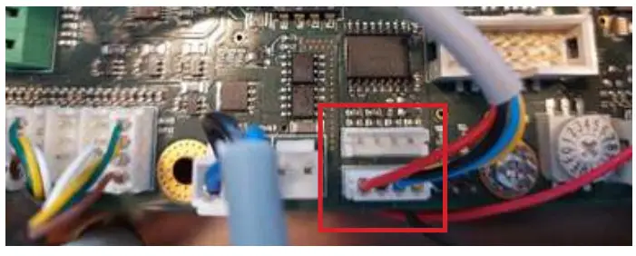
- Disconnect the Display cable connected to either of the two modbus terminals

- Connect the USB cable (110007946) to either one of the Modbus connectors
- Connect USB cable to PC
- Power on inverter by using service switch (AWARE OF HIGH VOLTAGE IN INVERTER!)
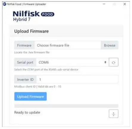
- Start up Firmware upgrade program (Can be downloaded from Nilfisk FOOD web)

- Click browse to select upgrade file *.hex (Can be downloaded from Nilfisk FOOD web)
- Click in Serial port up/down to select the com port for a USB cable, if comport is not showing press the “refresh” button
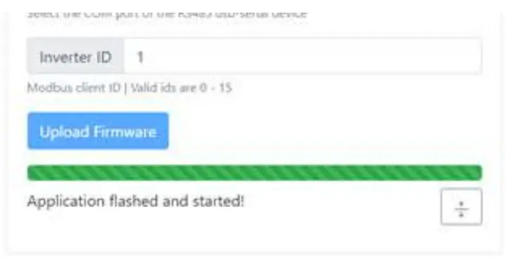
- If necessary change inverter ID to match Inverter ID, Default is 1
- Press Upload Firmware, and wait for the progress bar to reach the end and turn green
- The progress bar will start moving

- Power off the unit using service switch (wait for the unit to discharge approximately 5 min.)
- Disconnect the usb cable from the inverter
- Connect the display to Modbus connector again
- Mount the lit of the inverter box
- Turn the unit back on.
![]() © 2014 All rights reserved
© 2014 All rights reserved
Distributor:


