![]() 01599 18 Inch Metal Cutting Bandsaw
01599 18 Inch Metal Cutting Bandsaw
User Manual
DECLARATION OF CONFORMITY
Declaration of Conformity
We
SIP (Industrial Products) Ltd
Gelders Hall Road
Shepshed
Loughborough
Leicestershire
LE12 9NH
England
As the manufacturer within the UK, England, Scotland & Wales declare that the
18″ Metal Cutting Bandsaw 230V – SIP Code 01599
Conforms to the requirements of the following regulation(s), as indicated
Supply of Machinery (Safety) Regulations 2008
Electrical Equipment (Safety) Regulations 2016
Electromagnetic Compatibility Regulations 2016
The Restriction of the Use of Certain Hazardous Substances in Electrical and Electronic Equipment Regulations 2012
And the relevant harmonised standard(s), including
BS EN 55014-1:2017+A11
BS EN 55014-2:2015
BS EN IEC 61000-3-2:2019
BS EN 61000-3-3:2013+A1
Mr P. Ippaso – Director – SIP (Industrial Products) Ltd
Date: 13/01/2022
SAFETY SYMBOLS USED THROUGHOUT THIS MANUAL
![]() Danger/Caution: Indicates risk of personal injury and/or the possibility of damage.
Danger/Caution: Indicates risk of personal injury and/or the possibility of damage.![]() Warning: Risk of electrical injury or damage!
Warning: Risk of electrical injury or damage!![]() Note: Supplementary information.
Note: Supplementary information.
SAFETY INSTRUCTIONS
![]() IMPORTANT: Please read the following instructions carefully, failure to do so could lead to serious personal injury and/or damage to the bandsaw.
IMPORTANT: Please read the following instructions carefully, failure to do so could lead to serious personal injury and/or damage to the bandsaw.
When using your bandsaw, basic safety precautions should always be followed to reduce the risk of personal injury and/or damage to the bandsaw. Read all of these instructions before operating the bandsaw and save this user manual for future reference.
The bandsaw should not be modified or used for any application other than that for which it was designed. Do not use this bandsaw for anything other than its intended purpose; this bandsaw is designed for metal cutting work in engineering workshops, garages, metal fabricators, etc.
If you are unsure of its relative applications do not hesitate to contact us and we will be more than happy to advise you. Before operating the bandsaw always check no parts are broken, and that no parts are missing. Always operate the bandsaw safely and correctly.
KNOW YOUR BANDSAW: Read and understand the owner’s manual and labels affixed to the bandsaw. Learn its applications and limitations, as well as the potential hazards specific to it.
KEEP CHILDREN AND UNTRAINED PERSONNEL AWAY FROM THE WORK AREA: All visitors should be kept at a safe distance from the work area; never allow untrained persons to operate the bandsaw. STAY ALERT: Always watch what you are doing and use common sense.
NEVER LEAVE THE BANDSAW UNATTENDED: When in use, or connected to the mains supply. KEEP WORK AREA CLEAN AND WELL LIT: Cluttered work areas and dark areas invite accidents. Floors must not be slippery due to oil, water or sawdust etc.
HAVE YOUR BANDSAW REPAIRED BY A QUALIFIED PERSON: The bandsaw is in accordance
with the relevant safety requirements. Repairs should only be carried out by qualified persons using original spare parts, otherwise this may result in considerable danger to the user and void the warranty. DANGER! Check that the bandsaw is in sound condition and good working order before each use; Take immediate action to repair or replace faulty / damaged parts. WARNING! Only operate on a level and stable surface.
WARNING! RISK OF ELECTRIC SHOCK. Do not expose the bandsaw to water spray, rain, dripping water or moisture of any kind. PROTECT YOURSELF FROM ELECTRIC SHOCK: When working with machinery, avoid contact with any earthed items (e.g. pipes, radiators, hobs and refrigerators, etc.). It is advisable wherever possible to use an RCD (residual current device) at the supply socket. DO NOT ABUSE THE MAINS LEAD: Never pull the mains lead to remove the plug from the mains socket, or to move the bandsaw from place to place. Keep the mains lead away from heat, oil and sharp edges. If the mains lead is damaged, it must be replaced by the manufacturer or its service agent or a similarly qualified person in order to avoid unwanted hazards.
ALWAYS check that the belt guard and blade guards are in place, adjusted correctly, undamaged and firmly attached. NEVER STAND ON THE BANDSAW: The bandsaw is not designed for this purpose. DO NOT dismantle, tamper with or modify the bandsaw, as this may be dangerous and will invalidate the warranty. SECURE THE WORK-PIECE: Use the vice to hold the work-piece; this frees up both hands to operate the saw.
REMOVE ADJUSTING KEYS AND WRENCHES: Form a habit of checking to see that keys and adjusting tools are removed from the bandsaw before every use.
If a problem with the bandsaw is experienced or suspected stop using the bandsaw immediately and contact your distributor for repair. Regularly inspect the bandsaw, ensuring that it is in good working order and condition. Always ensure that the work area is clean, tidy and free from unrelated materials. Keep away from flammable objects, materials & surfaces, use in a location where accidental contact (particularly by children) is unlikely. Ensure on/off switches are switched to off (0) before connecting mains lead to the power supply. Keep the work area clean and clear of possible tripping hazards. Keep children and unauthorised persons away from the bandsaw, as it has a sharp blade! Disconnect from the mains before moving or attempting any cleaning or maintenance. Keep hands and all other body parts away from the blade. Failure to follow the warnings in this manual, may result in personal injury and/or property damage. Turn the bandsaw off and disconnect it from the mains supply when moving from one location to another. Never operate the bandsaw without all guards in place. DO NOT get the bandsaw wet or use in damp or wet locations or areas where there is
- If a problem with the bandsaw is experienced or suspected stop using the bandsaw immediately and contact your distributor for repair.
- Regularly inspect the bandsaw, ensuring that it is in good working order and condition.
- Always ensure that the work area is clean, tidy and free from unrelated materials.
- Keep away from flammable objects, materials & surfaces, use in a location where accidental contact (particularly by children) is unlikely. Ensure on/off switches are switched to off (0) before connecting mains lead to the power supply.
- Keep the work area clean and clear of possible tripping hazards.
- Keep children and unauthorised persons away from the bandsaw, as it has a sharp blade! Disconnect from the mains before moving or attempting any cleaning or maintenance. Keep hands and all other body parts away from the blade.
- Failure to follow the warnings in this manual, may result in personal injury and/or property damage.
- Turn the bandsaw off and disconnect it from the mains supply when moving from one location to another.
- Never operate the bandsaw without all guards in place. DO NOT get the bandsaw wet or use in damp or wet locations or areas where there is condensation.
- DO NOT move the bandsaw whilst in
- DO NOT remove the blade guard or bet guard whilst the bandsaw is switched
- DO NOT allow unqualified persons to disassemble the bandsaw for any reason, the bandsaw must be checked by qualified personnel
- DO NOT use the bandsaw without the blade guard and belt guard closed, as this will lead to personal injury to you or others!
- WARNING if a fuse blows, ensure it is replaced with the correct fuse type and rating.
- DO NOT place any objects on the safety guard or on the covers at any time.
- When not in use, store the bandsaw carefully in a safe, dry. childproof location.
- NEVER cover the bandsaw during operation or whilst it cools after operation.
- Be aware of moving parts that occur during normal operation of this
- NEVER operate the bandsaw with damaged, broken or missing parts, or with any guards or covers removed.
- DO NOT operate the bandsaw or any electrical items with wet hands.
- Keep the floor around the machine clean and free of scrap material, oil and grease.
- ALWAYS keep the machine guards in place at all times when the machine is in operation, if removed for maintenance then use extreme caution, always refit the guards immediately after any maintenance.
- DO NOT over reach, always maintain a balanced stance so that you do not fall or lean into any moving parts.
- Keep all visitors at a safe distance.
- ALWAYS keep hands and fingers away from the blade when in operation.
- ALWAYS use the vice to secure your matetial, never cut any material without using the vice; this is extremely dangerous!
- ALWAYS have the belt guard closed at all times when the machine is in operation, failure to do this can lead to personal
- ALWAYS use adequate roller stands for supporting longer and heavier materials.
- ALWAYS use the correct blade, using the correct tpi blade for culling the material will make your job easier, and the blade last longer, using the wrong tpi blade will make a rough cut and will decrease the life of the
- NEVER force the blade through the material, this will decrease the life of the blade.
- ALWAYS keep the bandsaw as clean as possible and keep blades sharp for best and safest performance.
- ALWAYS wear approved eye and ear protection when operating the machine.
- If any dust is produced, wear an approved face or dust mask.
- WARNING! round bar and tubing have a tendency to roll whilst being cut and can cause the blade to slip, DO NOT cut such items without clamping or blocking the material.
- DO NOT start the bandsaw until the material is secure and the blade has been lowered to just above the material.
- NEVER use damaged or deformed bandsaw blades.
- ALWAYS secure the material that is too be cut in the
- NEVER use the bandsaw with the blade guard or pulley cover removed.
- DO NOT use whilst under the influence of drugs, alcohol or other intoxicating
- NEVER start the bandsaw with the blade in contact with the
- ALWAYS allow the bandsaw to reach full speed before commencing the cutting opera
- NEVER use this bandsaw for any application other than that specified by the manufactur
- NEVER operate this bandsaw under conditions not approved by the manufacturer.
- Before using or servicing your bandsaw, read and understand all instructions. Failure to follow safety precautions or instructions can cause equipment damage and/or serious personal
- WEAR THE CORRECT CLOTHING. Do not wear loose clothing, neckties, rings, bracelets, or other jewellery, which may get caught in moving parts. Non-slip footwear is recommend Wear protective hair covering to contain long hair. Roll long sleeves up above the elbow.
- Understand the operating environment; Before each use the operator should assess, understand and where possible reduce the specific risks and dangers associated with the operating Bystanders should also be made aware of any risks associated with the operating environment.
If the bandsaw is used in a place of work all rules and laws etc. relating to the use of portable electrical appliances should be followed.![]() When using the saw, particularly during extended periods; ensure the operator as well as those in the area wear ear protection.
When using the saw, particularly during extended periods; ensure the operator as well as those in the area wear ear protection.![]() When using the saw always ensure the operator as well as those in the area wear eye protection.
When using the saw always ensure the operator as well as those in the area wear eye protection.![]() Some materials have the potential to be highly toxic; always wear a face mask when operating the saw.
Some materials have the potential to be highly toxic; always wear a face mask when operating the saw.
![]() CAUTION: The warnings and cautions mentioned in this user manual can not cover all possible conditions and situations that may occur. It must be understood by the operator that common sense and caution are factors which cannot be built into this product, but must be applied.
CAUTION: The warnings and cautions mentioned in this user manual can not cover all possible conditions and situations that may occur. It must be understood by the operator that common sense and caution are factors which cannot be built into this product, but must be applied.
ELECTRICAL CONNECTION
WARNING! It is the responsibility of the owner and the operator to read, understand and comply with the following: You must check all electrical products, before use, to ensure that they are safe. You must inspect power cables, plugs, sockets and any other connectors for wear or damage.
You must ensure that the risk of electric shock is minimised by the installation of appropriate safety devices; A residual current circuit Breaker (RCCB) should be incorporated in the main distribution board.
We also recommend that a residual current device (RCD) is used. It is particularly important to use an RCD with portable products that are plugged into a supply which is not protected by an RCCB. If in any doubt consult a qualified electrician.
Connecting to the power supply:
The 18” Metal Cutting Bandsaw is fitted with a standard UK 13 amp type 230v ~ plug. Before using the welder inspect the cable and plug to ensure that neither are damaged. If any damage is visible have the tool inspected / repaired by a suitably qualified person. If it is necessary to replace the plug a heavy duty impact resistant plug would be preferable.
The wires for the plug are coloured in the following way:
| Yellow/green | Earth |
| Blue | Neutral |
| Brown | Live |
As the colours of the wires may not correspond with the markings in your plug, proceed as follows: The wire which is coloured blue, must be connected to the terminal marked with N or coloured black. The wire which is coloured brown, must be connected to the terminal, which is marked L or coloured red. The wire which is coloured yellow/green should be connected to the terminal which is coloured the same or marked![]()
Always secure the wires in the plug terminal carefully and tightly. Secure the cable in the cord grip carefully.
![]() Warning: Never connect live or neutral wires to the earth terminal of the plug. Only fit an approved plug with the correct rated fuse. If in doubt consult a qualified electrician.
Warning: Never connect live or neutral wires to the earth terminal of the plug. Only fit an approved plug with the correct rated fuse. If in doubt consult a qualified electrician.![]() Note: Always make sure the mains supply is of the correct voltage and the correct fuse protection is used. In the event of replacing the fuse always replace the fuse with the same value as the original.
Note: Always make sure the mains supply is of the correct voltage and the correct fuse protection is used. In the event of replacing the fuse always replace the fuse with the same value as the original.![]() Note: If an extension lead is required in order to reach the mains supply; ensure that this too is rated for the correct voltage and fuse rating.
Note: If an extension lead is required in order to reach the mains supply; ensure that this too is rated for the correct voltage and fuse rating.
GUARANTEE
This SIP bandsaw is covered by a 12 month parts and labour warranty covering failure due to manufacturers defects. This does not cover failure due to misuse or operating the bandsaw outside the scope of this manual – any claims deemed to be outside the scope of the warranty may be subject to charges Including, but not limited to parts, labour and carriage costs.
This guarantee does not cover consumables such as bearings, oil or blade etc.
In the unlikely event of warranty claims, contact your distributor as soon as possible.![]() Note: Proof of purchase will be required before any warranty can be honoured.
Note: Proof of purchase will be required before any warranty can be honoured.
TECHNICAL SPECIFICATIONS
| Name | 18″ Metal Cutting Bandsaw |
| Part number | 1599 |
| Input voltage | 230V — 50Hz |
| Circular 45° | 150mm |
| Circular 90° | 254mm |
| Rectangle 45° | 150 x 190mm |
| Rectangle 90° | 127 x 457mm |
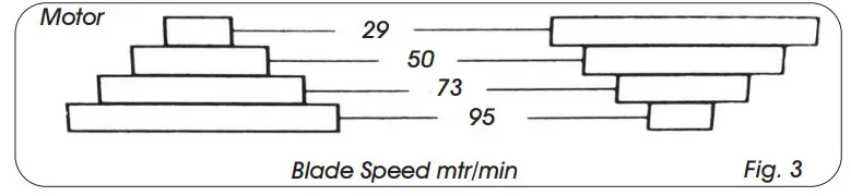
| Blade speed | 29, 50, 73 & 95 mtr/min |
| Blade size | 3280 x 0.9 x 27mm |
| Motor power | 2HP (1.5kw) |
| Drive | V-belt |
| Packed dimensions | 1830 x 830 x 1150mm |
| Net weight | 310 kg |
| Gross weight | 385 kg |
CONTENTS & ACCESSORIES
- Cut Off Stop.
- Coolant Tray.
- Instruction Manual (not pictured).

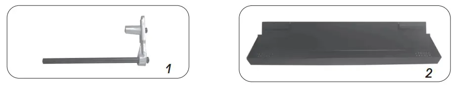
![]() Note: If any of the above are missing or damaged, contact your distributor immediately.
Note: If any of the above are missing or damaged, contact your distributor immediately.
GETTING TO KNOW YOUR BANDSAW
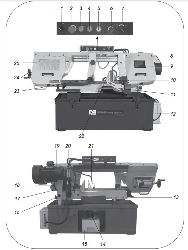
| Ref. No | Description |
| 1 | Coolant Pump Switch |
| 2 | Emergency Stop Button |
| 3 | Start Button |
| 4 | Stop Button |
| 5 | Power Light |
| 6 | Hydraulic Cylinder Feed Rate Adjuster |
| 7 | Bow Feed Lock |
| 8 | Belt Guard |
| 9 | Right Wheel Cover |
| 10 | Fixed Vice Jaw |
| 11 | Cut Off Stop |
| 12 | Electrical Box |
| 13 | Vice Handwheel |
| 14 | Coolant Pump |
| 15 | Coolant Tank |
| 16 | End Cut Microswitch |
| 17 | Pivot Arm |
| 18 | Gearbox |
| 19 | Motor |
| 20 | Hydraulic Cylinder |
| 21 | Coolant Nozzle |
| 22 | Movable Vice Jaw |
| 23 | Coolant Tap |
| 24 | Blade Tensioning Knob |
| 25 | Right Wheel Cover |
CONTROL PANEL
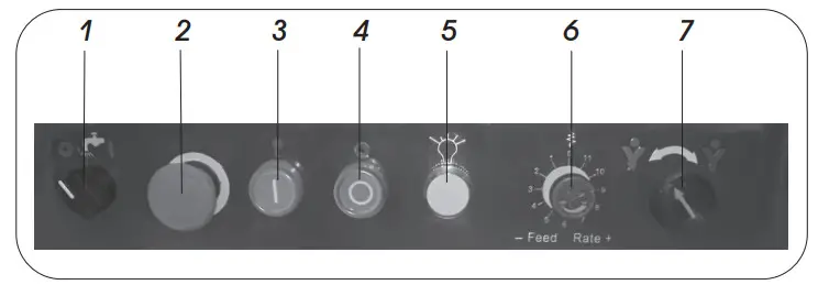
| 1. | Coolant Pump Switch | Turns the coolant pump on / off |
| 2. | Emergency Stop Button | Interrupts power to the system and stops the motor, twist the button until it pops out to bring power back to the machine, can also be used as a stop button. |
| 3. | Start Button | Turns the machine on. |
| 4. | Stop Button | Stops the machine. |
| 5. | Power Light | When lit the machine is ready for operation. |
| 6. | Hydraulic Cylinder Feed Rate Adjuster | Fine tunes the feed rate on the hydraulic cylinder, 9 is the fastest and 1 is the slowest rate of decent. |
| 7. | Bow Feed Lock | Turning the knob anti-clockwise lowers the saw bow at the rate you have set on the hydraulic cylinder, turning the knob clockwise will locks the bow into position. |
ASSEMBLY INSTRUCTIONS
UNPACKING
- Remove the bandsaw from the packaging, check the bandsaw for any signs of damage or missing items prior to assembly.
 Note: If any items are missing or damaged, DO NOT use the machine; contact your distributor immediately.
 - Whist still on the wooden base, move the bandsaw to where it is too be located.
- Unbolt the bandsaw from the wooden base.
 Danger / Caution: At least 2 persons are required to remove this bandsaw from it`s packaging it is extremely heavy! Failing to follow this can have serious consequences and could lead to personal injury and/or the possibility of damage.
 - Use proper lifting equipment to move the bandsaw from the wooden base and in to your desired location.
FITTING THE CUT OFF STOP
Slide the cut off stop (B) through the cut off stop bracket (11) on the front of the bandsaw, secure using the bolt on the side of the retaining bracket.
The cut off stop is ready to be used.
CLEANING THE SURFACES PRIOR TO OPERATION
Before using the bandsaw it is best to clean the rust protected surfaces using kerosene, diesel oil or mild solvent. Never use cellulose based solvents such as paint thinner or lacquer thinner as these will damage the painted surfaces.
REMOVING THE TRANSIT BOLT
Before the bandsaw can be used the transit bolt and bracket must be removed; this is situated at the end of the saw bow and bed (see right picture).
Keep the bolt and bracket as you may need these if the bandsaw needs to be moved in transit to a different location (Fig. 1).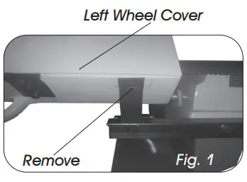
OPERATING INSTRUCTIONS
SETTING THE BLADE SPEED
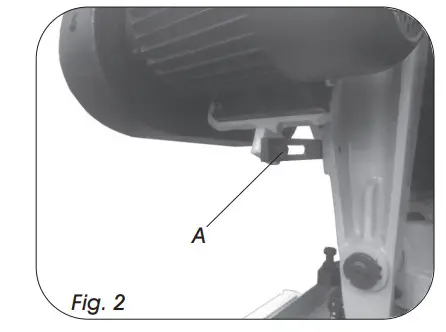
Prior to changing the blade speed make sure the mains is disconnected, Loosen and remove the belt guard bolt and lift up the cover, this will allow access to the belt so it can be adjusted.
- Loosen the motor bracket bolt (Fig.2, A), this will allow you to move the motor more freely.

- Move the belt to the desired speed (Fig.3).

- Once the belt has the desired speed adjustment, re-tension the motor and secure in place by tightening the bolt (Fig.2).
- Close the belt guard and refit and re-tighten the screw.
On page 15 is a table which will give you some idea of what speed materials should be cut at.
| Material | Speed M/Min (FPM) | Material | Speed M/Min (FPM) |
| Carbon Steel | 60 – 108 (196 – 354) | Tool Steel | 62 (203) |
| Steel Section | 54 – 67 (180 – 220) | High Speed Tool Steel | 23 – 36 (75 – 118) |
| Thin Tube | 54 – 67 (180 – 220) | Cold Work Tool Steel | 95 – 213 (29 – 65) |
| Aluminium Alloy | 67 – 163 (220 – 534) | Hot Work Tool Steel | 62 (203) |
| Copper Alloy | 70 – 147 (229 – 482) | Oil Hardening Tool steel | 62 – 65 (203 – 213) |
| Alloy Steel | 34 – 98 (111 – 321) | Free Machining Stainless Steel | 46 – 62 (150 – 203) |
| Mild Steel | 75 (246) | Gray Cast Iron | 33 – 75 (108 – 255) |
| Water Hard Tool Steel | 242 (74) | Ductile Austenitic Cast Iron | 65 – 85 (20 – 26) |
| Stainless Steel | 26 (85) | Malleable Cast Iron | 98 (321) |
| Rod Cold ss Ste Stainless | 26 – 62 (85 – 203) | ||
Note: The above table is an approximate guide reference only, various factors mean some materials may require different speeds to the ones quoted.
ADJUSTING THE VICE
- Loosen both lever locks (Fig. 4).
- Slide the fixed vice jaw to the left and move it to your desired angle.
- Once set at your desired angle re-tighten the lever lock.
- Place the material to be cut flush against the fixed vice jaw.
- Slide the movable vice jaw up tight against the material and tighten the lever lock.
- For maximum cutting at 90˚ remove the fixed vice jaw and bolt it down on the left hand side hole (Fig. 5, B).
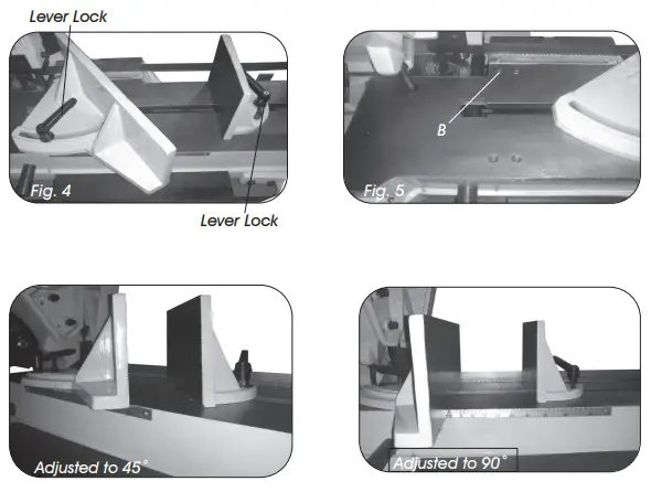
Note: Always tighten both lever locks prior to making a cut, leaving them loose will allow the jaws to slip and could damage the material or even cause personal injury.
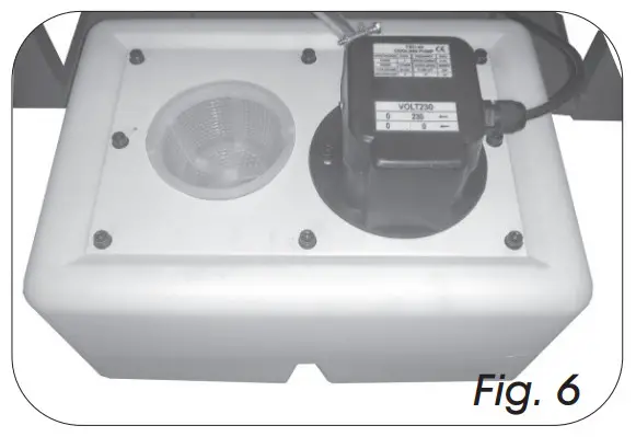
FILLING THE COOLANT TANK![]() Note: We recommend the use of water soluble coolant, this will prolong the blade life and make the cut more efficient.
Note: We recommend the use of water soluble coolant, this will prolong the blade life and make the cut more efficient.
- Slide the coolant tank out from the rear of the bandsaw (Fig. 6).
- Ensure the filter is fitted and fill with fresh coolant.
- Slide the coolant tank back onto the bandsaw panel, ensuring that the coolant hose is situated over the filter.

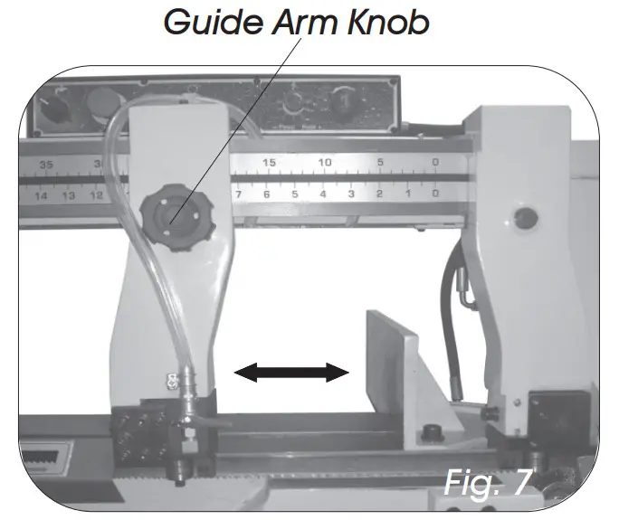
ADJUSTING THE GUIDE ARM
- Loosen the guide arm knob (Fig. 7).
- Slide the guide arm close to the material that is to be cut.
- Re-tighten the guide arm knob.

HYDRAULIC CYLINDER ADJUSTMENT
The hydraulic cylinder has an adjustable rate of decent, this can be adjusted by turning the hydraulic cylinder feed rate adjuster (Fig. 8) clockwise to slow down the rate of decent, or anti-clockwise to speed up the rate of decent. The hydraulic cylinder can be stopped in any position by turning the hydraulic cylinder feed rate adjuster , when the knob is fully turned clockwise the cylinder will stop descending.
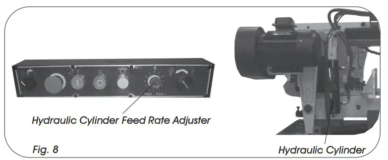
![]() Note: Check maintenance on how to replace the oil or top up the hydraulic cylinder.
Note: Check maintenance on how to replace the oil or top up the hydraulic cylinder.
CUTTING WITH THE BANDSAW![]() Danger: Before attempting to cut always ensure all covers are in place, undamaged and secure.
Danger: Before attempting to cut always ensure all covers are in place, undamaged and secure.![]() Note: The harder the material to be cut the slower the speed should be.
Note: The harder the material to be cut the slower the speed should be.
- Disconnect from the mains supply.
- Change the blade speed to suit the material that is to be cut (see pg14 changing the blade speed).
- Raise the saw bow to a vertical position.
- Adjust the cut length stop to your desired position.
- Set the vice angle to your desired position.
- Open the vice and insert the material to be cut then close the vice to secure.
- Move the two adjustable blade guides closer to the material, but make sure it doesn’t foul against it.
- Adjust the rate of descent of the arm as described on pg17 so that it is creeping slowly down towards the material, shut off the hydraulic cylinder when the blade gets close to the material, do not start cutting on a sharp edge, file it off first.
- Plug in to the mains supply and turn the coolant pump on.
- Start the saw.
![]() Caution: Do not turn the machine on until the material is secured and the blade has been lowered just above the material.
Caution: Do not turn the machine on until the material is secured and the blade has been lowered just above the material.
- To bring the blade in to contact with the material to be cut, turn the feed control knob, if the blade jams immediately turn the bandsaw off and refer to the troubleshooting guide.
- Once the cut is complete thenturn the machine off and remove the material.
Caution: Never remove the material when the bandsaw is still running, always switch the machine off before attempting to remove the material, failure to do this could lead to serious personal injury.
Caution: Never start the bandsaw with the blade in contact with the workpiece. Allow the saw to reach full speed before commencing cut.
MAINTENANCE INSTRUCTIONS
CHANGING THE BLADE![]() Caution: Before carrying out any maintenance always disconnect the bandsaw from the mains supply.
Caution: Before carrying out any maintenance always disconnect the bandsaw from the mains supply.![]() Caution: We strongly advise wearing gloves for protection when changing blades, blades are sharp and dangerous and can cause personal injury.
Caution: We strongly advise wearing gloves for protection when changing blades, blades are sharp and dangerous and can cause personal injury.![]() Danger/Caution: Blades are sharp use extra care when removing, installing or handling.
Danger/Caution: Blades are sharp use extra care when removing, installing or handling.
![]() Note: The bandsaw was designed to use a 3280 x 0.9 mm size blade, always use this size blade.
Note: The bandsaw was designed to use a 3280 x 0.9 mm size blade, always use this size blade.
- Disconnect from the mains supply.
- Raise the saw bow to around 6” and turn the feed control knob clockwise to lock it in position.
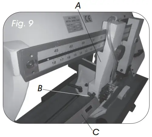
- Slide the left blade guard arm (Fig. 9, A) to the right.
- Take the two cap head bolts (Fig. 9, B) out and remove the adjustable blade guard bracket (Fig. 9, C).
- Open both wheel covers.
Release the blade tension by turning the blade tension handwheel anti-clockwise.
- Remove the blade from both wheels and slide it out of both blade guides.
Before fitting the new blade its best to clean the wheels of any swarf. - Place the new blade onto the wheels and between the blade guides.
- Tension the blade, re-adjust the blade guides and track the blade.
- Once adjustments have been made close both wheels covers and lower the saw bow.
TENSIONING THE BLADE![]() Caution: DO NOT over tension the blade as this will warp and stretch the blade, if the blade warps or stretches then it must be replaced.
Caution: DO NOT over tension the blade as this will warp and stretch the blade, if the blade warps or stretches then it must be replaced.![]() Note: Before tensioning the blade make sure the blade is properly aligned, If not, align before attempting to tension.
Note: Before tensioning the blade make sure the blade is properly aligned, If not, align before attempting to tension.
Blade tension is important for the proper operation of the bandsaw.
To set the blade correctly use the following steps. To tension the blade, lift up the left wheel cover and turn the blade tension hand-wheel (Fig. 10, A) clockwise, a tension scale (B) is located underneath the wheel. The scale is graduated to indicate blade tension of 20,000, 25,000 and 35,000 pounds per square inch (psi). For carbon blades (similar to the one supplied with the machine) the blade should be tensioned at 20,000 psi. For bi-metal blades, the blade should be tensioned at 25,000 or 35,000 psi. Always release the blade tension at the end of each work day to prolong blade life. 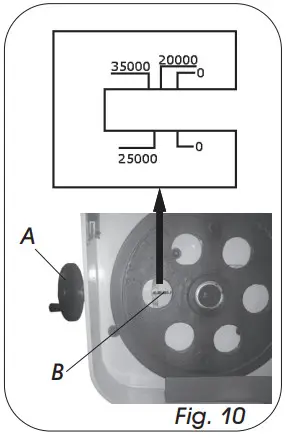
Note: The tension scale is a guide only; there are many factors that can alter the ideal tension of the blade.
BLADE GUIDE BEARING ADJUSTMENT![]() Note: The correct guide bearing adjustment is very important, this will make the blade run smoother and evenly without any snagging or twisting whilst the blade is running. It will also prolong the blade life.
Note: The correct guide bearing adjustment is very important, this will make the blade run smoother and evenly without any snagging or twisting whilst the blade is running. It will also prolong the blade life.![]() Note: The outer bearing shaft is eccentric and is the one to adjust, the inner bearing shaft is fixed and can not be adjusted.
Note: The outer bearing shaft is eccentric and is the one to adjust, the inner bearing shaft is fixed and can not be adjusted.
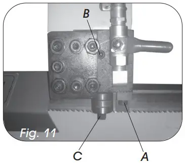
- Remove the carbide guide by taking out the cap head bolt (Fig. 11 ,A).
- Undo the hex screw slightly (Fig. 11, B).
- With a spanner turn the eccentric shaft (Fig. 11, C) until there is a gap of about 0.001”, you should just be able to slide a piece of paper between the gap.
- Once the eccentric shaft has be adjusted, retighten the hex screw (B) and refit the carbide guide.
- Repeat steps 2-5 for the opposite eccentric shaft.

BLADE GUIDE ALIGNMENT
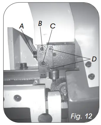
- Start with right fixed arm to begin with, place a set square on the bed and against the blade to see what adjustment is needed (Fig. 12).
- Make sure both cap head bolts (D) are tight before any adjustment is made. Slightly slacken off the cap head bolt (A) but do not remove.
- Slacken the nuts on screw (B & C), but do not remove them.
- Adjusting screw (B) will move the top part of the blade, or adjusting screw (C) will move the bottom part of the blade, screwing inwards will bend the blade towards you, screwing outwards will bend it away from you.
- Once the right side of the blade is adjusted correctly, then tighten both nuts up and re-tighten cap head bolt (A).

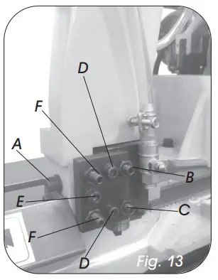
- Now adjust the left hand guide arm in the following way.
- Ensure both cap head bolts (Fig.13, D) are tight before any adjustment is made.
- Loosen the nuts on screws (Fig.13, B, C & F) but do not remove.
- Repeat step 5 for adjusting screws (B & C) for the angle of the blade.
- If the blade is not level to the right hand side of the blade, then adjust cap head bolt (E) to move the guide block inwards, or screws (F) to move it towards you.
- Once all the adjustments have been made, then tighten cap head bolt (A) back up and tighten all four nuts back up on screws (B, C & F).

FILLING THE HYDRAULIC CYLINDER WITH OIL
The hydraulic system on this bandsaw consists of a hydraulic cylinder which is operated by a needle valve, the saw bow is raised by hand, and as this is done oil passes to the underside of the piston. The restricted flow is controlled by the feed rate control knob and governs the speed of which the saw bow lowers. If it becomes necessary to fill the hydraulic cylinder with oil then follow the steps below.
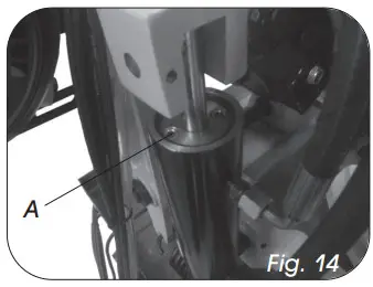
- Disconnect from the mains supply. Lower the saw bow into its lowest position.
- Remove the screw on top of the hydraulic cylinder (Fig.14, A) and fit a 1/8” bsp tail pipe fitting into its place.
- Place a hose over the tail pipe fitting and put the other end of the hose into a bottle of hydraulic oil.
- Raise and lower the saw bow a few times until the oil starts to seep out from the hydraulic cylinder.
- Once topped up take off the hose and tail pipe. Refit the screw.

GEARBOX OIL CHANGE![]() Note: The gearbox oil should be replaced after the first 50 hours of running andthen every 5 months after that, failing to do this will reduce the life of the gearbox, and void your warranty.
Note: The gearbox oil should be replaced after the first 50 hours of running andthen every 5 months after that, failing to do this will reduce the life of the gearbox, and void your warranty.
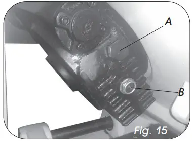
- Disconnect from the mains supply.
- Lower the saw bow to its lowest horizontal position.
- Remove the oil plug (Fig.15, A) and syphon the used oil out.
- Fill the gearbox with EP90 gear oil until its around the red dot on the oil sight glass.
- Refit the oil plug.

Note: Contact your local authority on how / where to dispose of the waste oil, we recommend refilling with EP90 gear oil.
GENERAL MAINTENANCE
- Do not used compressed air to clean the bandsaw, this can cause metal fillings to go into the guide bearings and other parts of the bandsaw.
- Always remove the metal fillings from the blade guides after use.
- Wipe the bandsaw down with a dry cloth.
- Check the guide bearings regularly making sure they are clean and properly adjusted.
- Always check to make sure the wire brush properly adjusted and clean.
- Always disconnect from the mains supply before carrying out any maintenance.
| Symptom | Possible cause | Solution |
| Unusual wear on side or back of blade. | 1. Blade guides are worn. 2. Blade guides not properly adjusted. 3. Blade guide brackets are loose. | 1. Replace blade guides. 2. Adjust as described in manual (pg15). 3. Tighten blade guide brackets. |
| Excessive blade breakage and teeth ripping from the blade. | 1. Material is loose in the vice. 2. Incorrect speed or feed. 3. Blade is too coarse. 4. Workpiece material is too coarse. 5. Incorrect blade tension. 6. Blade is in contact with material before bandsaw is started. 7. Blade is rubbing on the wheel flange. 8. Blade guides are misaligned. 9. Blade is too thick. 10.Bad weld on blade. | 1. Clamp the material securely. 2. Adjust speed or feed. 3. Use correct blade for material. 4. Use the saw at slower speed and use a smaller tpi blade. 5. Adjust blade tension (pg16-17) so that it does not slip on the wheel. 6. Place the blade in contact with the material only after the saw has started. 7. Adjust the blade tracking (pg18). 8. Adjust blade guide alignment. 9. Use correct thickness blade. 10.Re-weld or replace blade. |
| Motor overheating. | 1. Blade tension too high. 2. Drive belt tension too high. 3. Blade too coarse or too fine. 4. Gears need lubrication. 5. Blade is binding in the cut. | 1. Reduce blade tension. 2. Reduce belt tension. 3. Use a blade designed for the material. 4. Lubricate the gears. 5. Decrease feed and speed. |
| Blade is twisting. | 1. Blade tension is too high. 2. Blade is binding in the cut. | 1. Decrease blade tension. 2. Decrease feed pressure. |
| Bad, rough or crooked cuts. | 1. Blade is too coarse. 2. Blade guide assembly is loose. 3. Blade guides are spaced out too far. 4. Incorrect speed. 5. Blade is blunt. 6. Inadequate blade tension. 7. Blade guide bearings not properly adjusted. 8. Feed pressure too much. | 1. Use a finer blade. 2. Tighten the guide assembly. 3. Move guides closer to the material. 4. Adjust speed. 5. Replace the blade. 6. Increase blade tension a little at a time. 7. Adjust blade guide bearings. 8. Reduce feed pressure by increasing the spring tension on the arm. |
| Premature blade dulling. | 1. Blade tpi is too high. 2. Incorrect speed – too fast. 3. Inadequate feed pressure. 4. Hard spots or scale on the material. 5. Blade installed backwards. 6. Insufficient blade tension. 7. Work hardened material especially stainless. | 1. Replace with a smaller tpi blade. 2. Reduce speed. 3. Increase feed pressure by unscrewing tension bar. This will decrease the spring tension on the arm. 4. Reduce speed, increase feed pressure. 5. Remove blade, twist inside out and reinstall. 6. Increase blade tension. 7. Increase feed pressure by reducing spring pressure. |
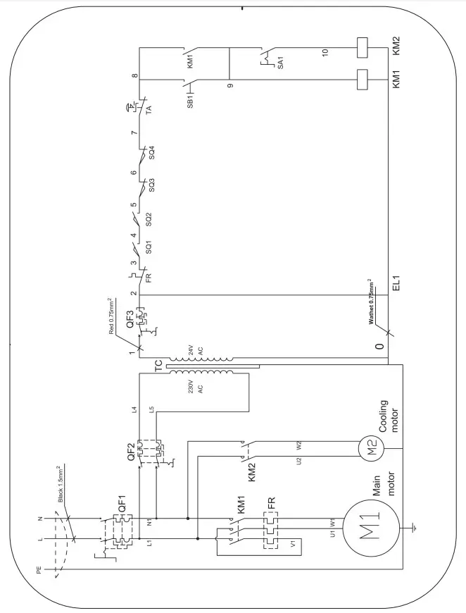
WIRING DIAGRAM
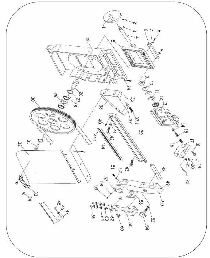
| Ref. No. | Description | SIP Part No. |
| 1 | Handwheel | WK04-00155 |
| 2 | Bolt M6x8 | WK04-00156 |
| 3 | Key 5×15 | WK04-00157 |
| 4 | Lead screw | WK04-00158 |
| 5 | Slide base | WK04-00159 |
| 6 | Bolt M10x25 | WK04-00107 |
| 7 | Washer M10 | WK04-00046 |
| 8 | Guide plate | WK04-00160 |
| 9 | Threaded ring | WK04-00161 |
| 10 | Belleville spring | WK04-00162 |
| 11 | Ring | WK04-00163 |
| 12 | Bearing | WK04-00164 |
| 13 | Slide stand | WK04-00165 |
| 14 | Washer | WK04-00166 |
| 15 | Bolt M12x20 | WK04-00167 |
| 16 | Pressure spring | WK04-00168 |
| 17 | Bracket | WK04-00169 |
| 18 | Bolt M10x65 | WK04-00170 |
| 19 | Screw | WK04-00171 |
| 20 | Washer | WK04-00172 |
| 21 | Nut M12 | WK04-00173 |
| 22 | Shaft | WK04-00174 |
| 24 | Spring washer | WK04-00175 |
| 25 | Idle wheel casting | WK04-00176 |
| 26 | Bushing | WK04-00177 |
| 27 | C-ring | WK04-00178 |
| 28 | Bearing | WK04-00179 |
| 29 | Spacer | WK04-00180 |
| 30 | Idle wheel | WK04-00181 |
| 31 | Bolt M10x20 | WK04-00051 |
| 32 | Left wheel cover | WK04-00182 |
| 33 | Handle | WK04-00183 |
| 34 | Bolt M6x12 | WK04-00038 |
| 36 | Spring pin 5×25 | WK04-00184 |
| 37 | Washer M10 | WK04-00046 |
| 37.1. | Bolt M10x30 | WK04-00185 |
| 38 | Rear support | WK04-00186 |
| 39 | Slide | WK04-00187 |
| 40 | Bolt M8x20 | WK04-00068 |
| 41 | Nut M12 | WK04-00173 |
| 42 | Bolt M12x40 | WK04-00048 |
| 43 | Bolt M12x30 | WK04-00189 |
| 44 | Scale | WK04-00190 |
| 44.1. | Rivet 2×5 | WK04-00191 |
| 45 | Bolt M6x12 | WK04-00038 |
| 46 | Washer M6 | WK04-00011 |
| 47 | Guard | WK04-00192 |
| 48 | Press plate | WK04-00193 |
| 49 | P clip | WK04-00194 |
| 50 | Guide arm | WK04-00195 |
| 51 | Bolt M8x20 | WK04-00068 |
| 52 | Nut M8 | WK04-00015 |
| 53 | Washer M8 | WK04-00014 |
| 54 | Adjustable knob | WK04-00196 |
| 55 | Seat | WK04-00197 |
| 56 | Middle plate | WK04-00198 |
| 57 | Press plate | WK04-00199 |
| 58 | Washer M6 | WK04-00011 |
| 59 | Bolt M6x20 | WK04-00016 |
| 60 | Clamp guide | WK04-00200 |
| 61 | Fixed bearing shaft | WK04-00201 |
| 62 | Eccentric bearing shaft | WK04-00202 |
| 63 | Bearing 608ZZ | WK04-00090 |
| 64 | Bearing 608ZZ | WK04-00090 |
| 65 | Ring | WK04-00203 |
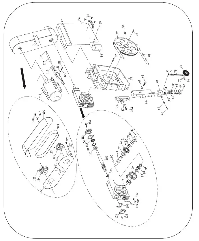
| 66 | Fixed arm | WK04-00204 |
| 67 | Bolt M8x45 | WK04-00205 |
| 68 | Hex head screw | WK04-00206 |
| 69 | Washer | WK04-00207 |
| 70 | Seat | WK04-00208 |
| 71 | Nut M12 | WK04-00173 |
| 72 | Pressure spring | WK04-00210 |
| 73 | Brush shaft | WK04-00211 |
| 74 | Steel brush | WK04-00212 |
| 75 | Spacer sleeve | WK04-00213 |
| 76 | Bolt M6x8 | WK04-00214 |
| 77 | Front support | WK04-00215 |
| 78 | Bolt M12x20 | WK04-00216 |
| 79 | Drive wheel | WK04-00217 |
| 80 | Drive wheel key | WK04-00218 |
| 81 | Blade 3280 x 19 x 0.80mm | 1415 |
| 81 | Blade 3280 x 19 x 0.90mm M42 | 1419 |
| 82 | Bolt M10x20 | WK04-00051 |
| 83 | Drive wheel casting | WK04-00219 |
| 84 | Right wheel cover | WK04-00220 |
| 85 | Bolt M6x12 | WK04-00038 |
| 86 | Cover | WK04-00221 |
| 87 | Bolt M5x12 | WK04-00093 |
| 88 | Shaft cover | WK04-00222 |
| 89 | O-ring | WK04-00223 |
| 90 | Seal | WK04-00224 |
| 91 | Bolt M8x20 | WK04-00068 |
| 92 | Shaft end cap | WK04-00225 |
| 93 | O-ring | WK04-00226 |
| 94 | Shaft | WK04-00227 |
| 95 | Key 10×50 | WK04-00228 |
| 96 | Nylon pad | WK04-00229 |
| 97 | Bearing | WK04-00230 |
| 98 | Ring | WK04-00231 |
| 99 | Worm wheel | WK04-00232 |
| 100 | Bearing | WK04-00233 |
| 101 | Gearbox casting | WK04-00234 |
| 102 | Bolt M6x12 | WK04-00038 |
| 103 | Gearbox cover | WK04-00235 |
| 104 | Gasket | WK04-00236 |
| 105 | Oil sight glass | WK04-00237 |
| 106 | Oil plug | WK04-00238 |
| 107 | O-ring | WK04-00239 |
| 108 | Bearing | WK04-00240 |
| 109 | Worm shaft | WK04-00241 |
| 110 | Bearing | WK04-00242 |
| 111 | Ring | WK04-00243 |
| 112 | Seal | WK04-00244 |
| 113 | Cover | WK04-00245 |
| 114 | Bolt M8x20 | WK04-00068 |
| 115 | Motor | WK04-00377 |
| 116 | Ring | WK04-00247 |
| 117 | Pivot shaft | WK04-00248 |
| 118 | Motor plate | WK04-00249 |
| 119 | Bolt M8x45 | WK04-00205 |
| 120 | Nut M8 | WK04-00015 |
| 121 | Washer M8 | WK04-00014 |
| 122 | Inner pulley cover | WK04-00250 |
| 123 | Bolt M8x20 | WK04-00068 |
| 124 | Motor pulley | WK04-00251 |
| 125 | Belt pulley | WK04-00252 |
| 126 | Key | WK04-00253 |
| 127 | Washer M8 | WK04-00014 |
| 128 | Bolt M8x20 | WK04-00068 |
| 129 | Belt | WK04-00254 |
| 130 | Outer pulley cover | WK04-00255 |
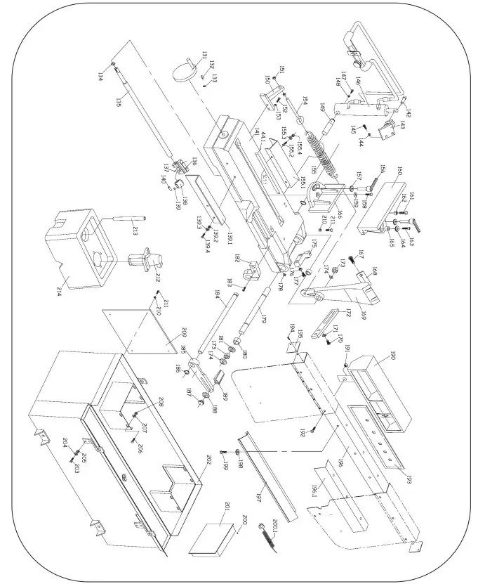
| 131 | Vice handwheel | WK04-00256 |
| 132 | Key | WK04-00257 |
| 133 | Bolt M6x8 | WK04-00258 |
| 134 | Washer M6 | WK04-00011 |
| 135 | Acme screw | WK04-00259 |
| 136 | Bracket | WK04-00260 |
| 137 | Bolt M5x8 | WK04-00035 |
| 138 | Acme nut | WK04-00261 |
| 139 | Pin | WK04-00262 |
| 139.1. | Connecting plate | WK04-00263 |
| 139.2. | Nut M8 | WK04-00015 |
| 139.3. | Bolt M8x20 | WK04-00068 |
| 139.4. | Washer M8 | WK04-00014 |
| 140 | Retainer | WK04-00264 |
| 141 | Base | WK04-00265 |
| 141.1. | Scale | WK04-00266 |
| 142 | Pin | WK04-00267 |
| 143 | Hyd. cylinder upper bracket | WK04-00268 |
| 144 | Washer M8 | WK04-00014 |
| 145 | Bolt M8x30 | WK04-00018 |
| 146 | Hydraulic cylinder | WK04-00269 |
| 147 | Bolt M8x16 | WK04-00013 |
| 148 | Washer M8 | WK04-00014 |
| 149 | Pivot shaft | WK04-00270 |
| 150 | Spring bracket | WK04-00271 |
| 151 | Nut M12 | WK04-00173 |
| 152 | Bolt M8x30 | WK04-00018 |
| 153 | Washer M8 | WK04-00014 |
| 154 | Eye bolt | WK04-00273 |
| 155 | Spring | WK04-00274 |
| 155.1. | Spring cover | WK04-00275 |
| 155.2. | Bolt M8x20 | WK04-00068 |
| 155.3. | Washer M8 | WK04-00014 |
| 155.4. | Nut M8 | WK04-00015 |
| 156 | Lever lock | WK04-00276 |
| 157 | Washer | WK04-00277 |
| 158 | Bolt M10x30 | WK04-00278 |
| 159 | Washer M10 | WK04-00046 |
| 160 | Fixed vice jaw | WK04-00279 |
| 161 | Bolt M12x70 | WK04-00280 |
| 162 | Nut M12 | WK04-00173 |
| 163 | Bolt M12x35 | WK04-00282 |
| 164 | Washer M12 | WK04-00049 |
| 165 | Bushing | WK04-00283 |
| 166 | Movable vice jaw | WK04-00284 |
| 167 | Bolt M10x30 | WK04-00285 |
| 168 | Press plate | WK04-00286 |
| 169 | Pivot arm | WK04-00287 |
| 170 | Bolt M8x25 | WK04-00137 |
| 171 | Washer M8 | WK04-00014 |
| 172 | Cover plate | WK04-00288 |
| 173 | Nut M24x1.5 | WK04-00289 |
| 174 | Washer | WK04-00290 |
| 175 | Position set bracket | WK04-00291 |
| 176 | Nut M10 | WK04-00052 |
| 177 | Screw | WK04-00292 |
| 178 | Bolt M10x35 | WK04-00045 |
| 179 | Shaft | WK04-00293 |
| 180 | Bearing | WK04-00294 |
| 181 | Washer | WK04-00295 |
| 182 | Bracket | WK04-00296 |
| 183 | Bolt M8x40 | WK04-00132 |
| 184 | Cut off stop shaft | WK04-00297 |
| 185 | Cut off stop | WK04-00298 |
| 186 | Ring | WK04-00299 |
| 187 | Bolt M6x12 | WK04-00038 |
| 188 | Washer M6 | WK04-00011 |
| 189 | Shaft | WK04-00300 |
| 190 | Switch | WK04-00301 |
| 191 | Nut M8 | WK04-00015 |
| 192 | Bolt M8x30 | WK04-00018 |
| 193 | Panel | WK04-00302 |
| 194 | Bolt M5x15 | WK04-00303 |
| 195 | End cover | WK04-00304 |
| 196 | Connecting beam | WK04-00305 |
| 196.1. | Protector | WK04-00306 |
| 197 | Protect cover | WK04-00307 |
| 198 | Washer M8 | WK04-00014 |
| 199 | Bolt M8x20 | WK04-00068 |
| 200 | Bolt M4x16 | WK04-00308 |
| 200.1. | Mains lead | WK04-00309 |
| 201 | Control box | WK04-00310 |
| 202 | Stand | WK04-00311 |
| 203 | Bolt M8x30 | WK04-00018 |
| 204 | Washer M8 | WK04-00014 |
| 205 | Nut M8 | WK04-00015 |
| 206 | Bolt M8x30 | WK04-00018 |
| 207 | Washer M8 | WK04-00014 |
| 208 | Nut M8 | WK04-00015 |
| 209 | Cover | WK04-00312 |
| 210 | Washer M6 | WK04-00011 |
| 211 | Bolt M6x20 | WK04-00016 |
| 212 | Coolant pump 230V | WK04-00378 |
| 213 | Hose | WK04-00314 |
| 214 | Coolant tank | WK04-00020 |
| N/A | QF1 Breaker | WK04-00379 |
| N/A | QF2 Breaker | WK04-00148 |
| N/A | QF3 Breaker | WK04-00149 |
| N/A | Contactor CN6 | WK04-00150 |
| N/A | Thermal relay 9-12.5A | WK04-00380 |
| N/A | Transformer | WK04-00381 |
| N/A | Blade guard microswitch | WK04-00154 |
DECLARATION OF CONFORMITY
Declaration of Conformity
We
SIP (Machinery Europe) Ltd
ASM Chartered Accountants
First Floor Block One
Quayside Business Park
Dundalk
County Louth
Republic of Ireland
As the manufacturer’s authorised representative within the EC declare that the
18” Metal Cutting Bandsaw 230V – SIP Code 01599
Conforms to the requirements of the following directive(s), as indicated
| 2006/42/EC | Machinery Directive |
| 2014/30/EU | Low Voltage Directive |
| 2011/65/EU | EMC Directive |
| 2014/35/EU | RoHS Directive |
And the relevant harmonised standard(s), including
EN 55014-1:2017+A1
EN 55014-2:2015
EN IEC 61000-3-2:2019
EN 61000-3-3:2013+A1
Mr P. Ippaso – Director – SIP (Industrial Products) Ltd
Date: 13/01/2022
![]() Please dispose of packaging for the product in a responsible manner. It is suitable for recycling. Help to protect the environment, take the packaging to the local amenity tip and place into the appropriate recycling bin.
Please dispose of packaging for the product in a responsible manner. It is suitable for recycling. Help to protect the environment, take the packaging to the local amenity tip and place into the appropriate recycling bin.![]() Never dispose of electrical equipment or batteries in with your domestic waste. If your supplier offers a disposal facility please use it or alternatively use a recognised re- cycling agent. This will allow the recycling of raw materials and help protect the environment.
Never dispose of electrical equipment or batteries in with your domestic waste. If your supplier offers a disposal facility please use it or alternatively use a recognised re- cycling agent. This will allow the recycling of raw materials and help protect the environment.
FOR HELP OR ADVICE ON THIS PRODUCT PLEASE CONTACT YOUR DISTRIBUTOR, OR SIP DIRECTLY ON:
TEL: 01509500400
EMAIL: [email protected] or [email protected]
www.sip-group.com


