Appendix A
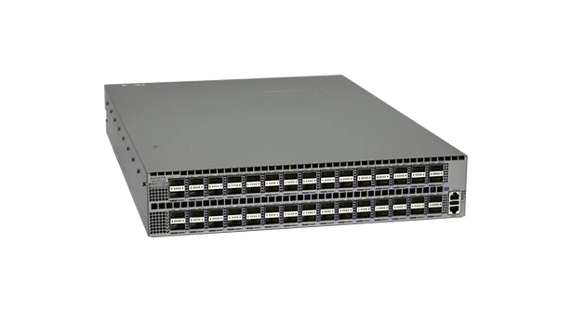
Quick Start Guide: 7280 Series 1 RU-Gen 3 Data Center Switches
Status Indicators
Front Indicators
A.1.1 Switch Indicators
Front panel LEDs are located on the right side of the chassis and display system, fan, and power supply status. The front panel LEDs are labeled either as in Figure A-1 or as in Figure A-2. Check your device for the specific method utilized.
Figure A-1: System Status Indicators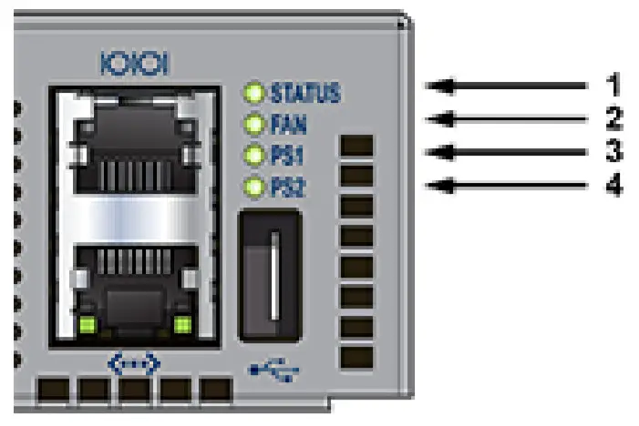
| 1. System status LED 2. Fan status LED | 3. Power supply 1 status LED 4. Power supply 2 status LED |
Figure A-2: System Status Indicators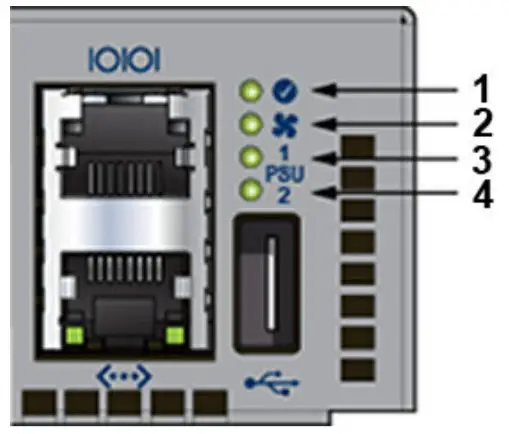
| 1 System status LED 2 Fan status LED | 3 Power supply 1 status LED 4 Power supply 2 status LED |
Table A-1 Switch Indicators LED States (Front)
| LED Name | LED State | Device Status |
| System Status LED | Blinking Green | The system is powering up. |
| Green | Normal operations. Due to power supply and fan redundancy, this LED will remain green if a single fan or power supply is missing or in a failed state. | |
| Blue | The locater function is active. | |
| Amber | Two or more fans (any combination of fan modules or PSU fans) are disconnected or malfunctioning. The switch will automatically execute a “graceful shutdown” shortly. | |
| Fan Status LED | Green | All fan and power modules are operating normally. |
| Amber | A single fan module is removed or malfunctioning. It is also amber when a PSU is completely removed or has a stuck fan rotor. | |
| Red | Two or more fans (any combination of fan modules or PSU fans) are disconnected or malfunctioning. The switch will automatically execute a “graceful shutdown” shortly. | |
| PSU [1:2] Status LED | Green | PSU is functioning and fully operational. AC is present, Aux output is ON, and Main output is ON. |
| Off | PSU has been removed or is not operating properly due to AC cord being unplugged, its fan rotor being stuck, or an internal fault. |
A.1.2 Port Indicators
Port LEDs, located in the vicinity of their corresponding ports, provide link and operational status.
Figure A-3 displays the Port LED location on the DCS-7050QX-32S switch.
Figure A-3: Port LEDs
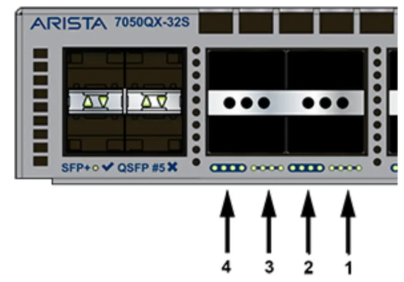
| 1. Port 4 LEDs 2. Port 3 LEDs | 3. Port 2 LEDs 4. Port 1 LEDs |
Table A-2 provides status conditions that correspond to port LED states. Port LED behavior for QSFP+ and SFP+ ports is consistent.
Table A-2 Port LED States (Front)
| LED State | Status |
| Off | Port link is down. |
| Green | Port link is up. |
| Yellow | Port is software disabled. |
| Flashing Yellow | Port failed diagnostics. |
Rear Status Indicators
Fan and power supply modules are accessed from the rear panel. Each fan and power supply module contains an LED that reports the module status.
Fan Status LEDs are on the fan modules, as displayed in Figure A-4.
Figure A-4: Fan Status LED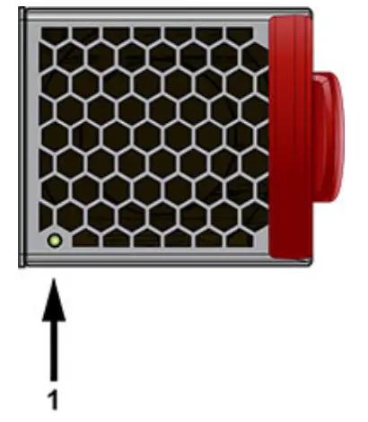
1 Fan module status LED
Table A-3 provides status conditions that correspond to fan status LED states.
Table A-3 Fan Status LED States (Rear)
| LED State | Status |
| Off | The fan module is not detected. If it is inserted, it may not be seated properly. |
| Green | The fan is operating normally. This LED state is exclusive to its fan module and independent of the states of its neighboring fans and power supplies. |
| Red | The fan has failed. |
The AC Power Supply Status LEDs are on the power supply modules, as displayed in Figure A-5.
Figure A-5: AC Power Supply Status LED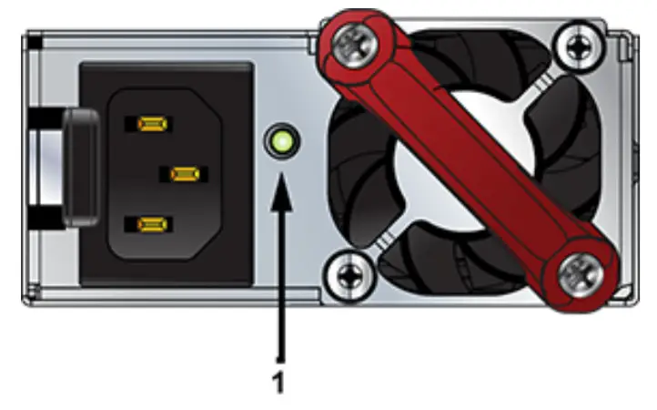
1 Power supply status LED
Table A-4 provides status conditions that correspond to the AC power supply status LED states.
Table A-4 AC Power Supply Status LED States (Rear)
| Power Supply State | PWR-500AC-F PWR-500ACR | PWR-745AC-F PWR-745AC-R | PWR-747AC-F PWR-747AC-R |
| Input power present Normal operation | Green | Green | Green |
| Input power present Power Supply fault | Yellow | Yellow | Yellow |
| No Input power Supply installed in chassis | Off | Off | Off |
| Input power present Supply not installed in chassis | Green | Green | Green |
The DC Power Supply Status LEDs are on the power supply modules, as displayed in Figure A-6.
Figure A-6: DC Power Supply Status LED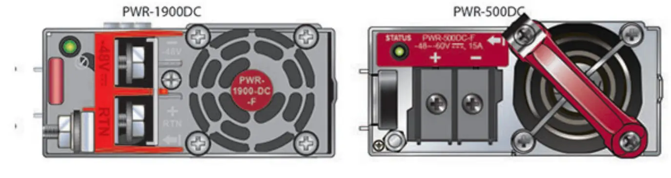
Table A-5 provides status conditions that correspond to the DC power supply status LED states.
Table A-5 DC Power Supply Status LED States (Rear)
| Power Supply State | PWR-500DC-F PWR-500DC-R | PWR-1900DC |
| Input power present Normal operation | Green | Green |
| Input power present Power Supply fault | Blinking Yellow | Blinking Yellow |
| No Input power Supply installed in chassis | Off | Off |
| Input power present Supply not installed in chassis | Blinking Yellow | Blinking Yellow |
Note
You can narrow down the error condition by logging in to the switch to view the specific device state.
Refer to the Arista User Manual’s Switch Environment Control chapter, under the topic Viewing Environment Status, for further information on the show environment commands.


