![]() Quick Start Guide
Quick Start Guide
Router
AWE-5310 AWE-5510
Arista Networks
www.arista.com
DOC-xxxxx-xx
AWE-5310 Router
| Headquarters 5453 Great America Parkway, Santa Clara, CA 95054 USA +1-408 547-5500 https://www.arista.com/en/ | Support +1-408 547-5502 +1-866 476-0000 mailto:[email protected] | Sales +1-408 547-5501 +1-866 497-0000 mailto:[email protected] |
© Copyright 2023 Arista Networks, Inc. All rights reserved. The information contained herein is subject to change without notice. The trademarks, logos and service marks (“Marks”) displayed in this documentation are the property of Arista Networks in the United States and other countries. Use of the Marks are subject to Arista Network Term of Use Policy, available at https://www.arista.com/en/terms-of-use. Use of marks belonging to other parties is for informational purposes only.
Chapter 1 Overview
This Quick Start Guide (QSG) describes the specifications and installation details of the Arista Router. This chapter includes the following topics:
- Scope
- Intended Audience
- Receiving and Inspecting the Equipment
- Installation Process
- Safety Information
- Obtaining Technical Assistance
- Product and Documentation Updates
1.1 Scope
This guide is intended for properly trained service personnel and technicians in necessary to install the following Arista Router.
This includes the following products:
- AWE-5310
- AWE-5510
1.2 Intended Audience
This guide can be referred to any qualified person who would like to install the device.![]() Note: Only qualified personnel should install, service, or replace this equipment.
Note: Only qualified personnel should install, service, or replace this equipment.
1.3 Receiving and Inspecting the Equipment
Upon receiving the router, inspect the shipping boxes and record any external damage. Retain packing materials if you suspect that part of the shipment is damaged; the carrier may need to inspect them.
If the boxes were not damaged in transit, unpack them carefully. Ensure that you do not discard any accessories that may be packaged in the same box as the main unit. Inspect the packing list and confirm that you received all listed items. Compare the packing list with your purchase order. Parts List provides a list of components included with the router.
1.4 Installation Process
The following steps are to be followed to install and usage of the router:
- Select and prepare the installation site.
- Assemble the installation tools listed.
- Attach the mounting brackets and install the router in an equipment rack.
- Connect the router to the power source and network devices.
- Configure the router.
1.5 Safety Information
Refer to the Arista Networks document Safety Information and Translated Safety Warnings available at https://www.arista.com/en/support/product-documentation
1.6 Obtaining Technical Assistance
Any customer, partner, reseller or distributor holding a valid Arista Service Contract can obtain technical support in any of the following ways:
Email: [email protected]. This is the easiest way to create a new service request.
Include a detailed description of the problem and the output of “show tech-support”.
Web: https://www.arista.com/en/support
A support case may be created through the support portal on our website. You may also download the most current software and documentation, as well as view FAQs, Knowledge Base articles, Security Advisories, and Field Notices.
Phone: +1 866-476-0000 or +1 408-547-5502.
1.7 Product and Documentation Updates
To receive important news on product updates, please visit our website at https://www.arista.com/en/support/product-documentation. We continuously enhance our product documentation based on customer feedback.
Chapter 2 Specifications
This section lists the specifications of Arista Routers described in this guide.
Table 1: Dimensions and Weights
| Router | Size (W x H x D) | Weight |
| AWE-5310 | 440 x 43.5 x 430 (mm) 17.32 x 1.71 x 16.92 (inches) | 9.3 (kg) 20.5 (lbs) |
| AWE-5510 | 440 x 88 x 520 (mm) 17.32 x 3.46 x 20.47 (inches) | 13.6 (kg) 29.98 (lbs) |
Table 2: Operating and Storage Temperature
| Router | Operating Attitude | Relative Humidity | ||
| Operating Temperature | Storage Temperature | |||
| AWE-5310 | 0 to 40°C (32°to 104°F) | -25 to 70°C (-13 to 158F) | 0 to 3,000 meters (0 to 10,000 feet) | 5 to 95% (non-condensing) |
| AWE-5510 | 0 to 40°C (32°to 104°F) | -25 to 70°C (-13 to 158F) | 0 to 3,000 meters (0 to 10.000 feet) | 5 to 95% (non-condensing) |
Table 3: Power Ratings
| Router | input Power Rating |
| AWE-5310 | 100 – 240VAC. 8 – 4A, 50/60 Hz |
| AWE-5510 | 100 – 240VAC, 10 – 5A, 50/60 Hz |
Table 4: System Configurations
| Router | Downlink Ports | Uplink Ports | Airflow | Power Supply | Fan |
| AWE-5310 | 4x10G/1G RJ45 | 4x10G/1G SFP+ | Front to rear | 2 | 4+1 |
| AWE-5510 | N/A | 16x10G/1G SFP-r | Front to rear | 2 | 3+1 |
Chapter 3 Preparation
This chapter describes the initial setup and preparation for installing the router. This chapter includes the following topics:
- Site Selection
- Tools and Parts Required for Installation
- Electrostatic Discharge (ESD) Precautions
3.1 Site Selection
The following criteria should be considered when selecting a site to install the router:
- Temperature and Ventilation: For proper ventilation, install the router where there is ample airflow to the front and back of the router. The ambient temperature should not go below 0° or exceed 40°C.
 Note: To prevent the router from overheating, do not operate it in an area where the ambient temperature exceeds 40°C (104°F).
 - Rack Space: Install the router in a rack or cabinet. The router height is 1.74″. The accessory kit provides necessary equipment such as mounting brackets and screws required for the installation. When mounting the router in a partially filled rack, load the rack from bottom to top, with the heaviest equipment at the bottom. Load the router at the bottom if it is the only item in the rack.
- Power Requirements: Power requirements vary by router and power supply model. Refer to Table 3: Power Ratings and for information regarding your specific system. Note: The power input plug-socket combination must be accessible at all times; it provides the primary method of disconnecting power from the system.
- Other Requirements: Select a site where liquids or objects cannot fall onto the equipment and foreign objects are not drawn into the ventilation holes. Verify the following guidelines are met:
- Clearance areas to the front and rear panels allow for unrestricted cabling.
- All front and rear panel indicators can be easily read.
- Power cords can reach from the power outlet to the connector on the rear panel.Note: All power connections must be removed to de-energize the unit.
3.2 Tools and Parts Required for Installation
Each router provides an accessory kit that contains parts that are required to install the router. In addition to the accessory kit, the following tools and equipment are required to install the router:
Additional Tools
- Screwdriver
- Screws or rack mounting nuts and bolts
3.3 Electrostatic Discharge (ESD) Precautions
Observe these guidelines to avoid ESD damage when installing or servicing the router.
- Assemble or disassemble equipment only in a static-free work area.
- Use a conductive work surface (such as an anti-static mat) to dissipate static charge.
- Wear a conductive wrist strap to dissipate static charge accumulation.
- Minimize handling of assemblies and components.
- Keep replacement parts in their original static-free packaging.
- Remove all plastic, foam, vinyl, paper, and other static-generating materials from the work area.
- Use tools that do not create ESD.
Chapter 4 Mounting the Router
This chapter provides the instructions to mount the router. This chapter includes the following topics:
- Four-Post Rack Mount
- Two-Post Rack Mount (Optional)
4.1 Four-Post Rack Mount
This section descibes instructions for four-post rack mounting the router.
To mount the router in a rack, you need to assemble the mounting brackets to the chassis, then attach the brackets to the rack posts. It includes:
- Attaching Mounting Brackets to the Chassis – 4 post
- Removing the Mounting Bracket from the Chassis
4.1.1 Attaching Mounting Brackets to the Chassis – 4 post
This section describes the steps to attach mounting brackets to the router chassis.
Figure 1: Attaching the Mounting Brackets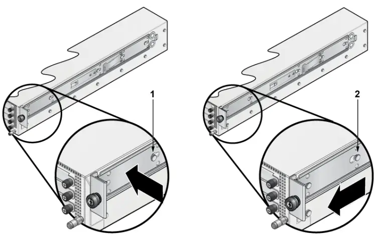
- Bracket clip before it is locked in place
- Bracket clip locked in place
![]() Note: Ensure that there is about 1U rack spacing between the two devices on the rack.
Note: Ensure that there is about 1U rack spacing between the two devices on the rack.
- Align the mounting brackets with the attachment pins.
- Place the bracket flush to the chassis with the attachment pins protruding through the key openings.
- Slide the bracket toward the front flange until the bracket clip locks (with an audible click).
4.1.2 Removing the Mounting Bracket from the Chassis
This section describes the steps to remove the mounting brackets from the router chassis.
- Lift the front edge of the mounting bracket clip with a flathead screwdriver.
- Slide the bracket away from the front flange (opposite from the installation direction).
4.2 Two-Post Rack Mount (Optional)
This section describes instructions for two-post rack mounting the router.
To mount the router in a rack, you need to assemble the mounting brackets to the chassis, then attach the brackets to the rack posts. It includes:
- Attaching Mounting Brackets to the Chassis
- Inserting the Router into the Rack
4.2.1 Attaching Mounting Brackets to the Chassis
This section describes the steps to attach mounting brackets to the router chassis.
Figure 2: Attaching the Mounting Brackets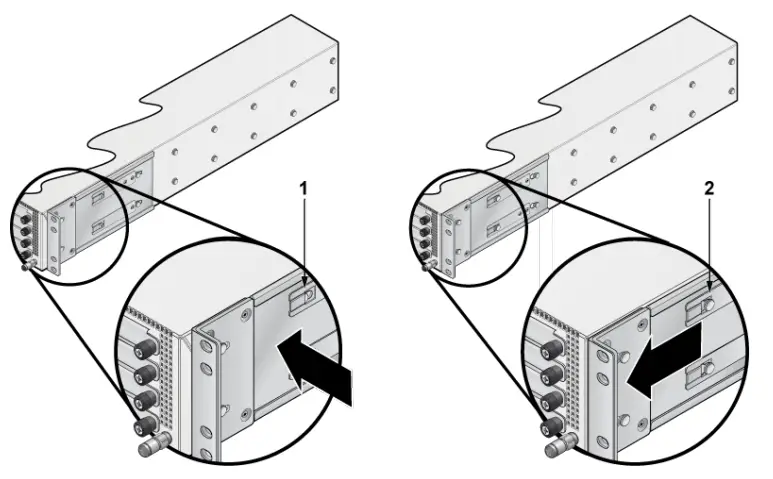
- Bracket clip installation
- Bracket clip removal
![]() Note: Ensure that there is about 1U rack spacing between the two devices on the rack.
Note: Ensure that there is about 1U rack spacing between the two devices on the rack.
- Position the bracket by aligning with the chassis holes on both the sides of the router and fix it with flat head screws.
- Secure the mounting brackets firmly to the router.
4.2.2 Inserting the Router into the Rack
This section describes the steps to insert the router into the rack.
Figure 3: Inserting the Router into the Rack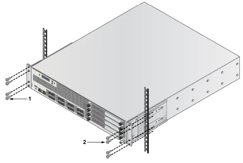
- Screws attaching chassis securely to rack
- Screws attaching chassis securely to rack
![]() Note: For thermal purposes, make sure that there is 1RU clearance above the rack mount bracket.
Note: For thermal purposes, make sure that there is 1RU clearance above the rack mount bracket.
- Lift the chassis, attached with brackets, into the rack.
- Place the router into the rack by aligning with the holes of the mounting bracket.
- Position the flanges against the rack posts.
- Attach the bracket flanges to the rack posts.
Chapter 5 LED Status Indicators
This section describes the front panel LED status of the device.
Table 5: LED Status Indicators
| LED Name | LED State | Device Status |
| System Status LED | Off | No power or in the midst of a power cycle. |
| Blinking Green | System is powering up. | |
| Green | The system is operating in a normal initialization sequence. Normal operations. | |
| Blue | The locator function is active. | |
| Amber | System is malfunctioning. System is overheating or temperature sensors have recorded passing the SW defined critical threshold. The device will automatically execute a “graceful shutdown” shortly. | |
| Cloud Connect Status LED | Off | Not connected to the cloud. |
| Green | System is connected to the cloud. | |
| Amber | Problem connecting to the cloud. | |
| Fan Status LED | Green | All fan modules are operating normally. |
| Amber | Single fan module is malfunctioning. | |
| Power Supply Status LED | Off | Power supply unit is not available. |
| Green | Power supply unit is fully functional. | |
| Amber | Power supply unit has a fault. |
Chapter 6 Parts List
Each router provides an accessory kit that contains parts that are required to install the router. This section lists the installation parts contained in the router accessory kit. Default Accessories
The following accessories are available along with the router box:
- Four-post rack mount kit

- Console Cables
- RJ45 ethernet cable
- Console cable
- Power cable (specified during time of purchase as it’s country specific or no power cord)
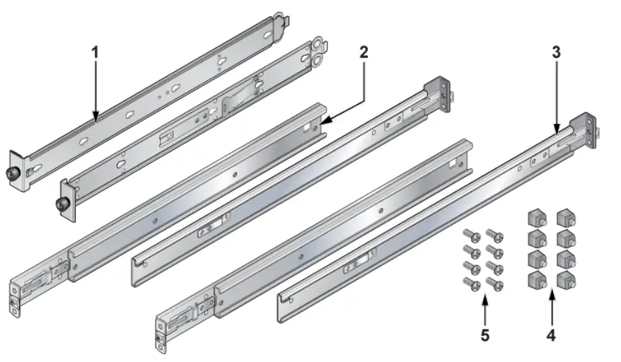
Optional Accessories
The following are the optional accessories:
· Two-post rack mount kit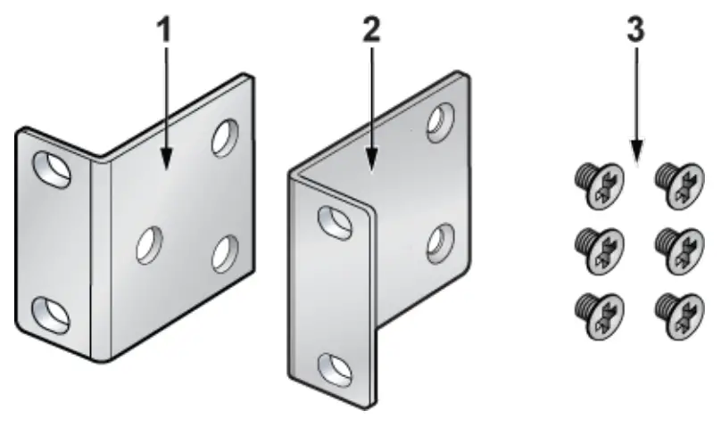 SKU and Product Details
The following are the list of SKU numbers related to the respective product.
Table 6: SKU and Product Details
| SKU | Product Description |
| AWE-5310 | Arista 5310, 4x10G/IG RJ45, 4x10G/IG SFP+ router, front to rear air, 48W AC Arista 5310, 4x RJ45 (w/2x Fail to Wire) 4x1OG SFP+, 2 NIM slots, front to rear air, 2 550W AC |
| AWE-5510 | Arista 5510, 8x SFP+ 10G, 8x SFP+ 10G Enhanced, 4 NIM slots, front to rear air, 2 800W AC |
Chapter 7 Front Panel
This section describes the front panel of each router.
7.1 AWE-5310
The AWE-5310 front panel includes the following key components:
Figure 4: AWE-5310 Front Panel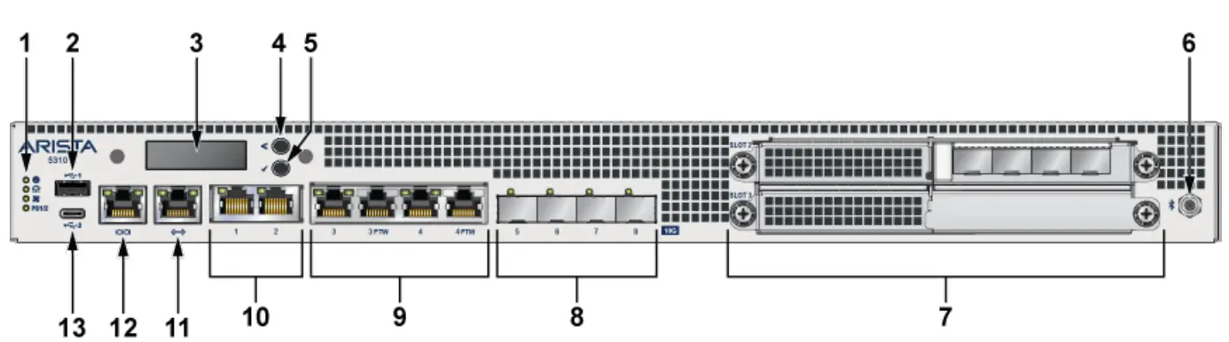
| 1 | System status LEDs |
| 2 | USB port Type-A |
| 3 | LCD Panel |
| 4 | LCD Upper Button |
| 5 | LCD Lower Button |
| 6 | SMA Connector |
| 7 | 2xLFF OCP NIC 3.0 slot |
| 8 | 4x10G SFP+ ports |
| 9 | 4x1G/1 oG RJ45 (2 ports support FTW) |
| 10 | 2x1G/10G RJ45 |
| 11 | RJ45 ethernet management port |
| 12 | Console port |
| 13 | USB port Type-C |
7.2 AWE-5510
The AWE-5510 front panel includes the following key components:
Figure 5: AWE-5510 Front Panel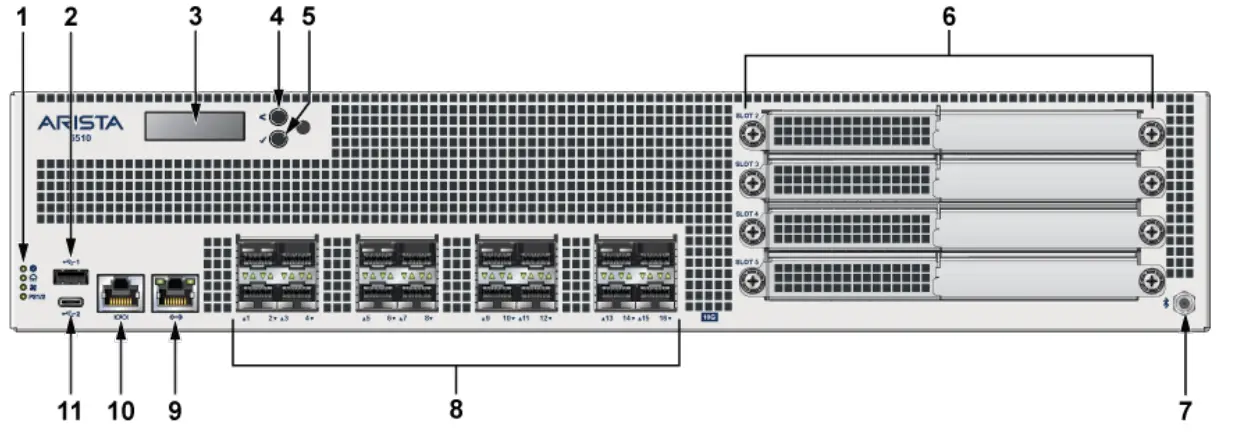
| 1 | System status LEDs |
| 2 | USB port Type-A |
| 3 | LCD Panel |
| 4 | LCD Upper Button |
| 5 | LCD Lower Button |
| 6 | 4xLFF OCP NIC 3.0 slot |
| 7 | SMA Connector |
| 8 | 16x1OG SFP+ ports |
| 9 | RJ45 ethernet management port |
| 10 | Console port |
| 11 | USB port Type-C |
Chapter 8 Rear Panel
The section describes the rear panel of each router.
8.1 AWE-5310
The AWE-5310 rear panel includes the following key components:
Figure 6: AWE-5310 Rear Panel
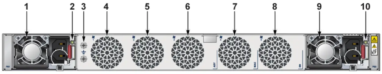
| 1 | Power Supplyl (PSI) |
| 2 | PSI LED |
| 3 | Earth grounding point |
| 4 | Fan 1 |
| 5 | Fan 2 |
| 6 | Fan 3 |
| 7 | Fan 4 |
| 8 | Fan 5 |
| 9 | Power Supply2 (PS2) |
| 10 | PS2 LED |
8.2 AWE-5510
The AWE-5510 rear panel includes the following key components:
Figure 7: AWE-5510 Rear Panel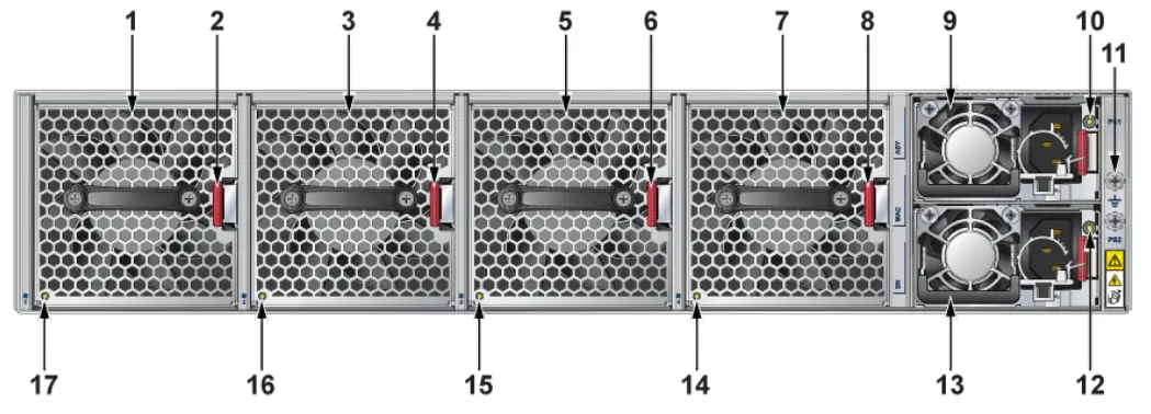
| 1 | Fan Module 1 |
| 2 | Fan Module Latch |
| 3 | Fan Module 2 |
| 4 | Fan Module Latch |
| 5 | Fan Module 3 |
| 6 | Fan Module Latch |
| 7 | Fan Module 4 |
| 8 | Fan Module Latch |
| 9 | Power Supply1 (PSI) |
| 10 | PSI LED |
| 11 | Earth grounding point |
| 12 | PS2 LED |
| 13 | Power Supply2 (PS2) |
| 14 | Fan Status LED |
| 15 | Fan Status LED |
| 16 | Fan Status LED |
| 17 | Fan Status LED |
Chapter 9 Regulatory Model Numbers
This section lists the Regulatory Model Numbers (RMNs) of the routers described in this document.
Table 7: RMNs
| SKU Number | Regulatory Model Number (RMN) |
| AWE-5310 | AN1791 |
| AWE-5510 | AN1792 |
Appendix A EMC Class A Notices and Warnings
Refer to the following sections for detailed EMC Class A Notices and Warnings.
Traditional Chinese Class A EMC Statement (Taiwan)
Federal Communication Commission Interference Statement Federal Communication Commission Interference StatementThis device complies with Part 15 of the FCC Rules. Operation is subject to the following two conditions: (1) This device may not cause harmful interference, and (2) this device must accept any interference received, including interference that may cause undesired operation. This equipment has been tested and found to comply with the limits for a Class B digital device, pursuant to Part 15 of the FCC Rules. These limits are designed to provide reasonable protection against harmful interference in a residential installation. This equipment generates, uses and can radiate radio frequency energy and, if not installed and used in accordance with the instructions, may cause harmful interference to radio communications. However, there is no guarantee that interference will not occur in a particular installation. If this equipment does cause harmful interference to radio or television reception, which can be determined by turning the equipment off and on, the user is encouraged to try to correct the interference by one of the following measures:
– Reorient or relocate the receiving antenna.
– Increase the separation between the equipment and receiver.
– Connect the equipment into an outlet on a circuit different from thatto which the receiver is connected.
– Consult the dealer or an experienced radio/TV technician for help.
FCC Caution:
Any changes or modifications not expressly approved by the party responsible for compliance could void the user’s authority to operate this equipment. This transmitter must not be co-located or operating in conjunction with any other antenna or transmitter.
Radiation Exposure Statement:
This equipment complies with FCC radiation exposure limits set forth for an uncontrolled environment. This equipment should be installed and operated with minimum distance 20cm between the radiator & your body.
Canada Statement
This device complies with ISED’s licence-exempt RSSs. Operation is subject to the following two conditions: (1) This device may not cause harmful interference, and (2) this device must accept any interference received, including interference that may cause undesired operation.
Radiation Exposure Statement:
This equipment complies with ISED radiation exposure limits set forth for an uncontrolled environment. This equipment should be installed and operated with greater than 20cm between the radiator & your body.
Class A (Korean) Statement This equipment has KC approval to be used in business environments, and if used in a home environment, there is a risk of radio wave interference.
Traditional Chinese Statement
For low-power radio frequency equipment that has obtained certification, companies, firms, or users are not allowed to change the frequency, increase the power, or change the characteristics and functions of the original design without approval. The use of low-power radio-frequency equipment must not affect flight safety and interfere with legal communications; if any interference is found, it should be stopped immediately, and it can only be used after improvement until there is no interference. The aforementioned legal communication refers to radio communication operated in accordance with the provisions of the Telecommunications Management Act. Low-power radio frequency equipment must endure the interference of legal communication or industrial, scientific and medical radio wave radiation electrical equipment.
Brazil Statement
This equipment is not entitled to protection against harmful interference and must not cause interference to properly authorized systems.
For more information, see the ANATEL website – http://www.anatel.gov.br
This product is not suitable for use in home environments, as it may cause electromagnetic interference that forces the user to take necessary measures to minimize this interference
Mexico Statement
Operation of this equipment is subject to the following two conditions: (1) this equipment or device may not cause harmful interference, and (2) this equipment or device must accept any interference, including interference that may cause undesired operation.
Class A Notice for EU
Warning: Operation of this equipment in a residential environment could cause radio interference.
This device complies with Directive 2014/53/EU and UK Radio Equipment Regulations 2017 SI 2017/1206. issued by the Commission of the European Community.
– Declaration of Conformity
Please added certification standard in your user manual which depended on the test standards your device performed. or
– If the DoC should be a simplified version, please take below as reference
Hereby, [Name of manufacturer] declares that the radio equipment type [designation of type of radio equipment] is in compliance with Directive 2014/53/EU and UK Radio Equipment Regulations 2017 SI 2017/1206.
The full text of the EU declaration of conformity is available at the following internet address: The frequency and maximum transmitted power in EU are listed as bellows: 2400 – 2500 MHz
VCCI Class A Warning for Japan


