Generalmetals MD18IU-021BW Package Heat Pump and Air Conditioning
Product Information
The product is a package heat pump and air conditioning unit, featuring R-410A refrigerant and a 14 SEER rating. It is available in sizes ranging from 2 to 5 tons. The unit comes with installation instructions that must be followed by qualified licensed service personnel for proper installation, adjustment, and operation of the unit. The instructions include important safety information that must be read thoroughly before attempting installation or operation. Failure to follow the instructions may result in improper installation, adjustment, service, or maintenance, possibly resulting in fire, electrical shock, property damage, personal injury, or death.
Product Usage Instructions
- Read the installation instructions thoroughly before attempting installation or operation.
- Only qualified licensed service personnel should install, adjust, and operate the unit.
- Disconnect all power to the unit before starting maintenance.
- Do not connect return ductwork to any other heat producing device such as a fireplace insert or stove.
- All phases of installation must comply with national, state, and local codes.
- If additional information is required, contact your local distributor.
RECOGNIZE THIS SYMBOL AS AN INDICATION OF IMPORTANT SAFETY INFORMATION
WARNING
These instructions are intended as an aid to qualified licensed service personnel for proper installation, adjustment and operation of this unit. Read these instructions thoroughly before attempting installation or operation. Failure to follow these instructions may result in improper installation, adjustment, service or maintenance possibly resulting in fire, electrical shock, property damage, personal injury or death.
DO NOT DESTROY THIS MANUAL
Please read carefully and keep in a safe place for future reference by a serviceman.
This document is customer property and is to remain with this unit.
These instructions do not cover all the different variations of systems nor does it provide for every possible contingency to be met in connection with installation.
All phases of this installation must comply with NATION, STATE AND LOCAL CODES. If additional information is required please contact your local distributor.
SAFETY
When you see the symbols below on labels or in the manual, be alert to the potential or immediate hazards of personal injury, property and/or product damage. It is the owner’s or installer’s responsibility to comply with all safety instructions and information accompanying these symbols.
- WARNING: This is a safety alert symbol indicating a potential hazardous situation, which could result in personal injury, property and/or product damage or death.
- CAUTION: This is a safety alert symbol indicating a potential hazardous situation, which could result in moderate personal injury, and/or property and product damage.
WARNING
- These instructions are intended as an aid to qualified, licensed service personnel for proper installation, adjustment and operation of this unit. Read these instructions thoroughly before attempting installation or operation. Failure to follow these instructions may result in improper installation, adjustment, service or maintenance possibly resulting in fire, electrical shock, property damage, personal injury or death.
- The manufacturer’s warranty does not cover any damage or defect to the heat pump caused by the attachment or use of any components, accessories or devices (other than those authorized by the manufacturer) into, onto or in conjunction with the heat pump. You should be aware that the use of unauthorized components, accessories or devices may adversely affect the operation of the heat pump and may also endanger life and property. The manufacturer disclaimer any responsibility for such loss or injury resulting from the use of such unauthorized components, accessories or devices.
- Disconnect all power to the unit before starting maintenance. Failure to do so can result in severe electrical shock or death.
- Do not, under any circumstances, connect return ductwork to any other heat producing device such as a fireplace insert, stove, etc. Unauthorized use of such devices may result in fire, carbon monoxide poisoning, explosion, property damage, severe personal injury or death.
- The unit must be permanently grounded. A grounding lug is provided. Failure to ground this unit can result in fire or electrical shock causing property damage, severe personal injury or death.
- Only electric heater kits supplied by this manufacturer as described in this publication have been designed, tested, and evaluated by a nationally recognized safety testing agency for use with this unit. Use of any other manufactured electric heaters installed within this unit may cause hazardous conditions resulting in property damage, fire, bodily injury or death.
- Proposition 65: This appliance contains fiberglass insulation. Respirable particles of fiberglass are known to the state of California to cause cancer.
CAUTION
Only use this unit in well-ventilated spaces and ensure that there are no obstructions that could impede the airflow into and out of the unit.
Do not use this unit in the following locations:
- Locations with mineral oil.
- Locations with saline atmospheres, such as seaside locations.
- Locations with sulphurous atmospheres, such as near natural hot springs.
- Where high voltage electricity is present, such as in certain industrial locations.
- On vehicles or vessels, such as trucks or ferry boats.
- Where exposure to oily or very humid air may occur, such as kitchens.
- In proximity to sources of electromagnetic radiation, such as high-frequency transmitters or other high strength radiation devices.
INSPECTION
As soon as unit is received, it should be inspected and noted for possible shipping damage during transportation. It is carrier’s responsibility to cover the cost of shipping damage. Manufacturer or distributor will not accept the claims from dealer for any transportation damage.
LIMITATIONS
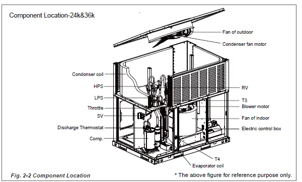
Refer to Fig. 2-3, 2-4,2-6,2-7 for unit physical data and to Table 6-1,6-2 for electrical data.
If components are to be added to a unit they must meet local codes, they are to be installed at the dealer’s and /or the customer’s expense.
Size of unit for proposed installation should be based on heat loss / heat gain calculations made in accordance with industry recognized procedures identified by the Air conditioning contractors of America.
INSTALLATION
PRE-INSTALLATION
Before installation, carefully check the following:
- Unit should be installed in accordance with national and local safety codes, including but not limit to ANSI/NFPS No. 70 or Canadian Electrical Code Part 1, C22.1, local plumbing and wastewater codes and any other applicable codes.
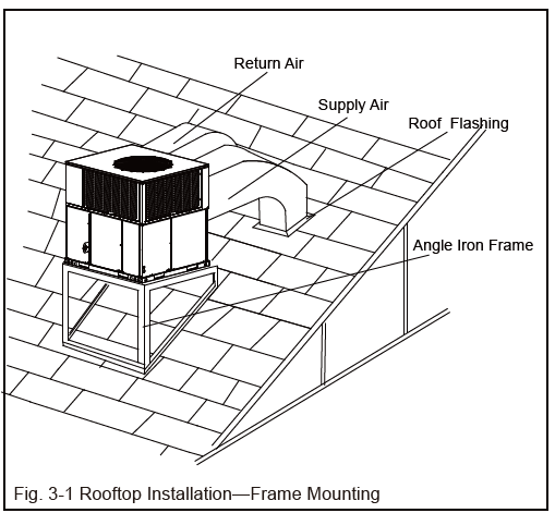
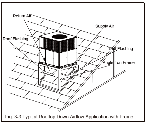
- For rooftop installation, be sure the structure has enough strength to support the weight of unit. Unit should be installed on roof curb and leveled.
- For ground level installation, a level slab should be used.
- Condenser airflow should not be restricted.
- On applications when a roof curb is used, the unit must be positioned on the curb so the front of the unit is tight against the curb.
RIGGING AND HANDING
Exercise care when moving the unit. Do not remove any packaging until the unit is near the place of installation. Rig the unit by attaching chain or cable slings to the lifting holes provided in the base rails. Spreader bars, whose length exceeds the largest dimension across the unit, MUST be used across the top of the unit.
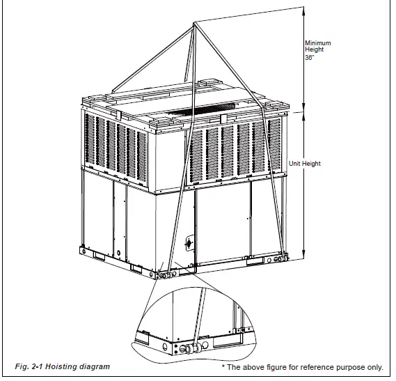
CAUTION
Before lifting, make sure the unit weight is distributed equally on the rigging cables so it will lift evenly.
Units may be moved or lifted with a forklift. Slotted openings in the base rails are provided for this purpose.
CAUTION
Check the electric wire, water and gas pipeline layout inside the wall, floor and ceiling before installation. Do not implement drilling unless confirm safety with the user, especially for the hidden power wire. An electroprobe can be used to test whether a wire is passing by at the drilling location, to prevent physical injury or death caused by insulation broken cords.
WARNING
Check the power supply before installation. Ensure that the power supply must be reliably grounded following local, state and National Electrical Codes. If not, for example, if the ground wire is detected charged, installation is prohibited before it is rectified. Otherwise, there is a risk of fire and electric shock, causing physical injury or death.
Unit Dimensions
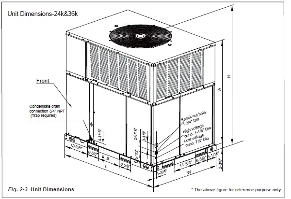
| Model size | Dimensions | ||||
| Heat Pump | “L” in.[mm] | “W” in.[mm] | “H” in.[mm] | “A” in.[mm] | “B” in.[mm] |
| 24,34566 | 50-/16 [1287]
| 35-1/16 [891]
| 46-13/16 [1190]
| 44-1/16 [1120]
| 11-3/4 [298]
|
Dimensions Back and Bottom-24K&36K
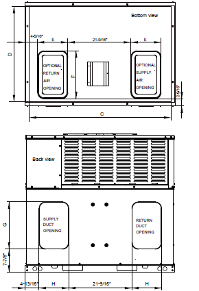
| Model size | Dimensions | |||||
| Heat Pump | “C” in.[mm] | “D” in.[mm] | “E” in.[mm] | “F” in.[mm] | “G” in.[mm] | “H” in.[mm] |
| 24,36 | 47-13/16 [1215] | 32-1/4 [820] | 9-15/16 [252] | 15-7/8 [403] | 15-3/4 [400] | 9-3/4 [249] |
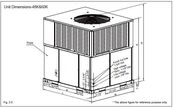
| Model size | Dimensions | ||||
| Heat Pump | “L” in.[mm] | “W” in.[mm] | “H” in.[mm] | “A” in.[mm] | “B” in.[mm] |
| 48,60 | 51-9/16 [1310] | 44-13/16 [1140] | 51-7/16 [1306] | 47-5/16 [1202] | 19-11/16 [500] |
Dimensions Back and Bottom-48K&60k
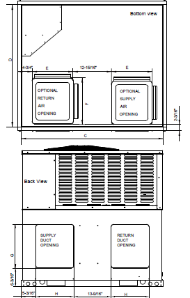
| Model size | Dimensions | |||||
| Heat Pump | “C” in.[mm] | “D” in.[mm] | “E” in.[mm] | “F” in.[mm] | “G” in.[mm] | “H” in.[mm] |
| 48,60 | 49-1/4 [1250]
| 42-1/2 [1080]
| 14-1/8 [358]
| 16-1/8 [409]
| 15-7/8 [403]
| 13-7/8 [352] |
NOTE
For units applied with a roof curb, the minimum clearance may be reduced from 1 inch to 1/2 inch between combustible roof curb material and this supply air duct.
Roof Curb
On applications when a roof curb is used,the unit must be positioned on the curb so the front of the unit is tight against the curb.(See Fig.2-8 ROOF CURB DIMENSIO)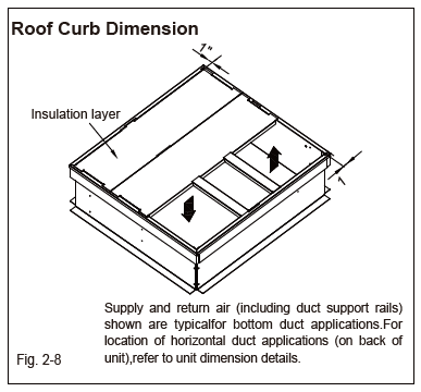
For units applied with a roof curb, the minimum clearance may be reduced from 1 inch to 1/2 inch between combustible roof curb material and this supply air duct.
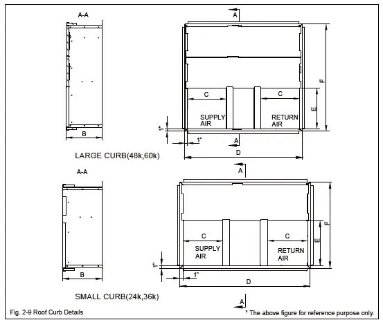
| CURB | Dimensions(Inches) | ||||
| “B” in.[mm] | “C” in.[mm] | “D” in.[mm] | “E” in.[mm] | “F” in.[mm] | |
| LARGE | 14-1/4 [362] | 15-1/4 [387] | 46-1/16 [1170] | 16 [406] | 42-3/16 [1070] |
| SMALL | 14-1/4 [362] | 14 [356] | 46-1/16 [1170] | 16 [406] | 30-5/8 [778] |
All panels must be secured in place when the unit is lifted. The condenser coils should be protected form rigging cable damage with plywood or other suitable material.
Location restrictions
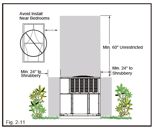
Ensure the top discharge area is unrestricted for at least 60 inches above the unit.
Do not locate outdoor unit near bedrooms since normal operational sounds may be objectionable.
Position unit to allow adequate space for unobstructed airflow, wiring, refrigerant lines, and serviceability.
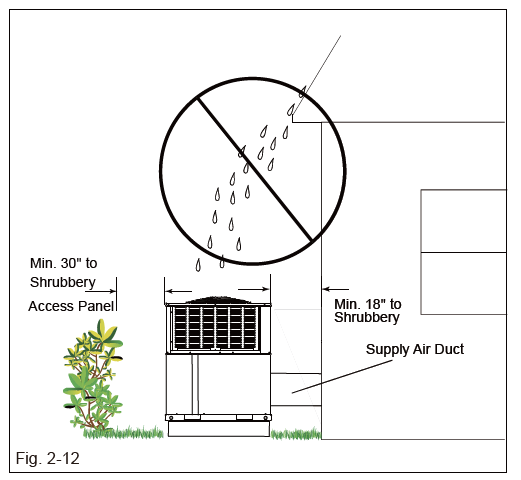
Allow a minimum of 12 in. clearance on one side of access panel to a wall and a minimum of 24 in. on the adjacent side of access panel.
Maintain a distance of 24 in. between units.
Position unit where water, snow, or ice from roof or overhang cannot fall directly on unit.(See Fig.2-11 and Fig.2-12.)
CAUTION:
Cold climate considerations (heat pump only)
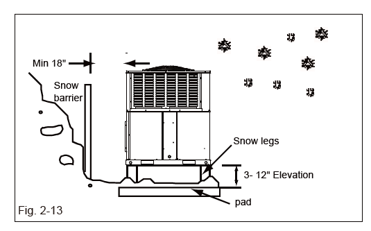
Precautions must be taken for units being installed in areas where snow accumulation and prolonged below-freezing temperatures occur.
- Units should be elevated 3-12 inches above the pad or rooftop, depending on local weather. This additional height will allow drainage of snow and ice melted durIng defrost cycle prior to its refreezlng. Ensure that drain holes in unit base pan are not obstructed, preventing drainage of defrost water (See Fig.2-13).
- If possible, avoid locations that are likely to accumulate snow drifts. If not possible, a snow drift barrier should be installed around the unit to prevent a build-up of snow on the sides of the unit.
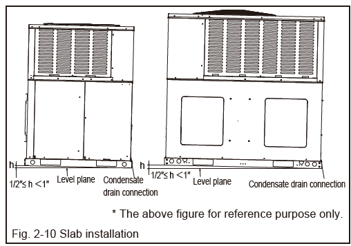
Note: Make sure that Condensate Drain side is not higher than the other side (Fig.2-10).
DUCTWORK
Ductwork should be sized and installed by the installing contractor in accordance with the Manual D from the Air Conditioning Contractors of America, and all national, state and local codes.
On ductwork exposed to outside air space, use at least 2” of insulation and a vapor barrier. Flexible joint may be used to reduce noise.
A closed return duct system shall be used. This shall not preclude use of economizers or ventilation air intake. Flexible joints may be used in the supply and return duct work to minimize the transmission of noise.
CAUTION:
When fastening duct work to the side duct flanges on the unit, insert the screws through the duct flanges only. DO NOT insert the screws through the casing. Outdoor duct work must be insulated and waterproofed.
NOTE:
Be sure to note supply and return openings. Refer to Fig. 2-7 for information concerning supply and return air duct openings.
After the unit is installed, there should be no open passages through the supporting structure that would permit flame or hot gases from a fire originating in the space below the supporting structure to travel to the space above that structure.
NOTE:
A unit with electric heaters with an inlet or outlet duct that penetrates the building structure supporting the unit shall be provided with a mounting base of noncombustible material so designed that, after the unit is installed, there will be no open passages through the supporting structure that would permit flame or hot gases from a fire originating in the space below the supporting structure to travel to the space above that structure. If the unit is intended to be installed on a supporting structure of combustible material, the base shall be so designed that the required clearance will be maintained between the supporting unit mounting base, and shall extend not less than 76 mm (3 in.) below the upper surface of the supporting structure, except that, in a unit designed for use only in a mobile home, the distance shall be not less than 19 mm (3/4 in.).
CONDENSATE DRAIN CONNECTION
Consult local codes for special requirements.
To provide extra protection from water damage, install an additional drain pan, provided by installer, under the entire unit with a separate drain line. Manufacturer will not be responsible for any damages due to the failure to follow these requirements.
INSTALL DRAIN PIPE
- Use the provided female NPT threaded fitting for outside connection and make sure that drain holes are not blocked.
- Insulation may be needed for drain line to prevent sweating.
- Use a sealing compound on male pipe threads. Install the condensate drain line (NPT) to spill into an open drain.
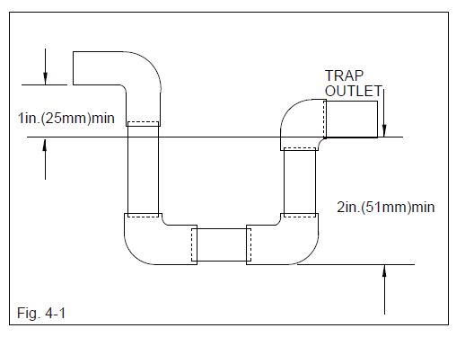
- Ensure a trap is included in the condensate drain line.
- Make sure that the outlet of the trap is at least 1 in.(25mm) lower than the drain pan condensate connection to prevent the pan from overflowing (See Fig. 4-1 ).
- Unit must be slightly inclined toward drain connection.(See Fig. 2-10).
REMOVAL AND CLEAN THE DRAIN PAN
See above Figure.4-1 B, disconnect the Connective Tube and Drain Commutator, screw off the two fixed screws of Drain Pan, and then along with the rail pull out the Drain Pan and Connective Tube from the bottom of evaporator. Using a wet cloth or water to wash out the drain pan carefully.
FILTERS
Units are shipped without a filter or filter racks. It is the responsibility of the installer to secure a filter in the return air ductwork or install a filter/frame Kit.
Filter must always be used and must be kept clean. When filter become dirt laden, insufficient air will be delivered by the blower, decreasing your units efficiency and increasing operation costs and wear-and tear on the unit and controls.
Filters should be checked monthly; this is especially important since this unit is used for both heating and cooling.
ELECTRICAL WIRING
Field wiring must comply with the National Electric
Code (NEC) or Canadian Electrical Code (CEC) and any applicable local ordinance.
WARNING
Disconnect all power to unit before installing or servicing. More than one disconnect switch may be required to de-energize the equipment. Hazardous voltage can cause severe personal injury or death.
POWER WIRING
- Proper electrical power should be available at unit. Voltage tolerance should not be over 10% from rating voltage.
- If any of the wire must be replaced, replacement wire must be the same type as shown in nameplate, wiring diagram and electrical data sheet.
- Install a branch circuit disconnect of adequate size to handle starting current, located within sight of, and readily accessible to the unit.
- ELECTRIC HEATER – If the Electric Heater is installed, unit may be equipped with 30~60A. circuit breakers or fuse. These breaker(s) protect the internal wiring in the event of a short circuit and serve as a disconnect. Circuit breakers installed within the unit do not provide over-current protection of the supply wiring and therefore may be sized larger than the branch circuit protection.
- Supply circuit power wiring must be 221 °F minimum copper conductors only. See Electrical Data in this section for ampacity, wire size and circuit protector requirements. Supply circuit protective devices may be either fuses or “HACR” type circuit breakers.
- An 1-3/8” knockouts inside cabinet is provided for connection of power wiring to electric heater.
- Power wiring is connected to the power terminal block in unit electric cabinet.
See Electrical Heater Installation Instruction for details
GROUNDING
WARNING
The unit must be permanently grounded. Failure to do so can result in electrical shock causing personal injury or death.
- Grounding may be accomplished by grounding metal conduit when installed in accordance with electrical codes to the unit cabinet.
- Grounding may also be accomplished by attaching ground wire(s) to ground lug(s) provided in the unit wiring compartment.
CONTROL WIRING
IMPORTANT: Class 2 low voltage control wiring SHOULD NOT be run in conduit with main power wiring and must be separated from power wiring, unless class 1 wire of proper voltage rating is used.
- Low voltage control wiring should be 18 AWG color-coded. For lengths longer than 50 ft, 16 AWG wire should be used.
- Two 7/8” holes can be used for control wires going into the unit, one on left side and one at the bottom.
- Make sure, after installation, separation of control wiring and power wiring has been maintained.
Thermostat should be mounted on an inside wall about 58” from floor and will not be affected by unconditioned air, sun and/or heat exposure. Follow the instruction carefully because there are many wiring requirements.
See Fig. 6-1 ~ 2, Table 6-1
Fig. 6-1 Typical Field Control Wiring Diagram
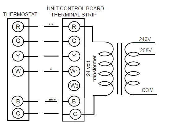
*** B wire be used with heat pump system only.
** Minimum wire size of 18 AWG wire should be used for all field installed 24 volt wire.
* Only required on units with supplemental electric heat.
CAUTION
Label all wire prior to disconnection when servicing controls. Wiring errors can cause improper and dangerous operation. Verify proper operation after servicing.
Fig. 6-2 Typical Field Power Wiring Diagram
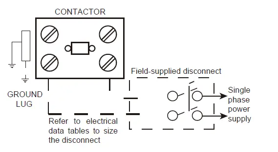
Table 6-1: 14 SEER Heat Pump W/Without Electric Heat
| Size (Tons) |
Vol | Compressor | OD Fan Motors | Supply Blower Motor | Heater Circuit(without units) | Heater Fan Speed | ||||||||
| RLA | LRA | FLA | FLA | Model | KW | Stages | Amps | MCA (Amps) | Max Fuse Breaker Size (Amps) | Low | Middle | High | ||
|
24(2.0) |
208/230-1-60 |
10.0 |
34.8 |
0.61 |
2.0 | None | – | – | None | 15.1 | 25 | |||
| EHK-05J | 3.8/5 | 1 | 18.1/20.8 | 23/26 | 25/30 | ● | ● | ● | ||||||
| EHK-08J | 5.6/7.5 | 1 | 27.1/31.3 | 34/40 | 35/40 | × | ● | ● | ||||||
| EHK-10J | 7.5/10 | 1 | 36.1/41.7 | 46/53 | 50/60 | × | ● | ● | ||||||
|
36(3.0) |
208/230-1-60 |
16.0 |
72 |
1.0 |
3.2 | None | – | – | None | 24.2 | 40 | |||
| EHK-05J | 3.8/5 | 1 | 18.1/20.8 | 23/26 | 25/30 | ● | ● | ● | ||||||
| EHK-08J | 5.6/7.5 | 1 | 27.1/31.3 | 34/40 | 35/40 | ● | ● | ● | ||||||
| EHK-10J | 7.5/10 | 1 | 36.1/41.7 | 46/53 | 50/60 | × | ● | ● | ||||||
| EHK-15J | 11.3/15 | 2 | 54.2/62.5 | 68/79 | 70/80 | × | ● | ● | ||||||
|
48(4.0) |
208/230-1-60 |
23.0 |
108 |
1.9 |
4.4 | None | – | – | None | 35.1 | 50 | |||
| EHK-05J | 3.8/5 | 1 | 18.1/20.8 | 23/26 | 25/30 | ● | ● | ● | ||||||
| EHK-08J | 5.6/7.5 | 1 | 27.1/31.3 | 34/40 | 35/40 | ● | ● | ● | ||||||
| EHK-10J | 7.5/10 | 1 | 36.1/41.7 | 46/53 | 50/60 | ● | ● | ● | ||||||
| EHK-15J | 11.3/15 | 2 | 54.2/62.5 | 68/79 | 70/80 | × | ● | ● | ||||||
| EHK-20J | 15/20 | 2 | 72.2/83.3 | 91/105 | 100/110 | × | × | ● | ||||||
|
60(5.0) |
208/230-1-60 |
26.0 |
127.9 |
1.9 |
4.0 | None | – | – | None | 38.4 | 60 | |||
| EHK-05J | 3.8/5 | 1 | 18.1/20.8 | 23/26 | 25/30 | ● | ● | ● | ||||||
| EHK-08J | 5.6/7.5 | 1 | 27.1/31.3 | 34/40 | 35/40 | ● | ● | ● | ||||||
| EHK-10J | 7.5/10 | 1 | 36.1/41.7 | 46/53 | 50/60 | ● | ● | ● | ||||||
| EHK-15J | 11.3/15 | 2 | 54.2/62.5 | 68/79 | 70/80 | × | ● | ● | ||||||
| EHK-20J | 15/20 | 2 | 72.2/83.3 | 91/105 | 100/110 | × | × | ● | ||||||
|
60(5.0) |
208/230-3-60 |
22.0 |
136.8 |
1.9 |
5.8 | None | – | – | None | 35.2 | 50 | |||
| EHK-10J | 7.5/10 | 1 | 36.1/41.7 | 46/53 | 50/60 | ● | ● | ● | ||||||
| EHK-15J | 11.3/15 | 2 | 54.2/62.5 | 68/79 | 70/80 | × | ● | ● | ||||||
| EHK-20J | 15/20 | 2 | 72.2/83.3 | 91/105 | 100/110 | × | × | ● | ||||||
| Component | Models | ||||
| Nominal Tonnage | 2.0 | 3.0 | 4.0 | 5.0 | 5.0 |
| Volt | 208/230-1-60 | 208/230-1-60 | 208/230-1-60 | 208/230-1-60 | 208/230-3-60 |
| ARI COOLING PERFORMANCE | |||||
| ARI net capacity (Btu) | 23200 | 34600 | 47000 | 58500 | 57000 |
| EER | 12.0 | 11.5 | 11.5 | 11.8 | 11.8 |
| SEER | 14.0 | 14.0 | 14.0 | 14.0 | 14.0 |
| Nominal CFM | 780 | 1200 | 1600 | 1850 | 1850 |
| System power (kW) | 1.93 | 3.01 | 4.09 | 4.96 | 4.83 |
| Refrigerant type | R410a | R410a | R410a | R410a | R410a |
| Refrigerant charge (lb-oz) | 6-3 | 7-4 | 9-4 | 12-6 | 13-4 |
| ARI HEATING PERFORMANCE | |||||
| 47°F Capacity Rating (Btu) | 22800 | 35000 | 48000 | 58500 | 57000 |
| System power (kW) | 1.70 | 2.69 | 3.91 | 4.56 | 4.58 |
| 17°F Capacity Rating (Btu) | 12100 | 19000 | 28500 | 32500 | 34500 |
| System power (kW) | 1.58 | 2.35 | 3.52 | 4.00 | 4.04 |
| HSPF | 8.2 | 8.2 | 8.2 | 8.0 | 8.0 |
| DIMENSIONS (Inches) | |||||
| Length | 50-11/16 | 50-11/16 | 51-9/16 | 51-9/16 | 51-9/16 |
| Width | 35-1/16 | 35-1/16 | 44-13/16 | 44-13/16 | 44-13/16 |
| Height | 46-13/16 | 46-13/16 | 51-7/16 | 51-7/16 | 51-7/16 |
| OPERATING WT. (lbs) | 400 | 411 | 537 | 568 | 557 |
| COMPRESSORS | |||||
| Type | Rotary | Rotary | Scroll | Scroll | Scroll |
| Quantity | 1 | 1 | 1 | 1 | 1 |
| CONDENSER COIL DATA | |||||
| Face area (Sq. Ft) | 14.11 | 14.11 | 20.17 | 20.17 | 20.17 |
| Rows | 2+2 | 2+3 | 2+2 | 3+3 | 3+3 |
| Fins per inch | 17 | 17 | 17 | 17 | 17 |
| Tube diameter | 9/32 | 9/32 | 9/32 | 9/32 | 9/32 |
| Circuitry type | interlaced | interlaced | interlaced | interlaced | interlaced |
| EVAPORATOR COIL DATA | |||||
| Face area (Sq. Ft) | 3.96 | 3.96 | 6.1 | 6.1 | 6.1 |
| Rows | 4 | 4 | 4 | 4 | 4 |
| Fins per inch | 17 | 17 | 17 | 17 | 17 |
| Tube diameter | 9/32 | 9/32 | 9/32 | 9/32 | 9/32 |
| Circuitry type | interlaced | interlaced | interlaced | interlaced | interlaced |
| Refrigerant control | Orifice | Orifice | Orifice | Orifice | Orifice |
| CONDENSER FAN DATA | |||||
| Fan diameter (inch) | 23-5/8 | 23-5/8 | 26-3/8 | 26-3/8 | 26-3/8 |
| Type | Prop | Prop | Prop | Prop | Prop |
| Drive type | Direct | Direct | Direct | Direct | Direct |
| No. speeds | 1 | 1 | 1 | 1 | 1 |
| Number of motors | 1 | 1 | 1 | 1 | 1 |
| Motor HP each | 1/12(60W) | 1/6(110W) | 1/3(290W) | 1/3(290W) | 1/3(290W) |
| RPM | 880 | 840 | 1070 | 1070 | 1070 |
| Nominal total CFM | 2200 | 2770 | 5100 | 5000 | 5000 |
| DIRECT DRIVE EVAP FAN DATA | |||||
| Quantity | 1 | 1 | 1 | 1 | 1 |
| Fan Size (Inch) | 10×10 | 10×10 | 11×10-5/8 | 11×10-5/8 | 11×10-5/8 |
| Type | Centrifugal | Centrifugal | Centrifugal | Centrifugal | Centrifugal |
| No. speeds | 1 | 1 | 1 | 1 | 1 |
| Motor HP each | 1/5(150W) | 1/2(375W) | 1/2(400W) | 3/4(600W) | 3/4(560W) |
AIRFLOW PERFORMANCE
Airflow performance data is based on cooling performance with a coil and no filter in place. Use this performance table for appropriate unit size, external static applied to unit and allow operation within the minimum and maximum limits shown in table below for both cooling and electric heat operation.
AIRFLOW PERFORMANCE DATA Table
Side Duct Application
| Model Number | Motor Speed | External Static Pressure-Inches W.C.[kPa] | |||||||||
| 0[0] | 0.1[.02] | 0.2[.05] | 0.3[.07] | 0.4[.10] | 0.5[.12] | 0.6[.15] | 0.7[.17] | 0.8[.20] | |||
|
24 | Low- Factory | CFM | / | 860 | 767 | 677 | 593 | / | / | / | / |
| Current/A | / | 1.0 | 1.0 | 1.0 | 1.0 | / | / | / | / | ||
| Power/W | / | 229 | 225 | 222 | 218 | / | / | / | / | ||
| Middle | CFM | / | / | / | 900 | 819 | 736 | 629 | / | / | |
| Current/A | / | / | / | 1.4 | 1.4 | 1.3 | 1.3 | / | / | ||
| Power/W | / | / | / | 314 | 309 | 303 | 298 | / | / | ||
| High | CFM | / | / | / | / | / | 868 | 761 | 653 | 600 | |
| Current/A | / | / | / | / | / | 1.7 | 1.7 | 1.7 | 1.7 | ||
| Power/W | / | / | / | / | / | 384 | 376 | 370 | 365 | ||
|
36 | Low (Tap2) | CFM | 1170 | 1107 | 1042 | 984 | 926 | 867 | 798 | / | / |
| Current/A | 1.6 | 1.6 | 1.7 | 1.7 | 1.8 | 1.8 | 1.9 | / | / | ||
| Power/W | 176 | 182 | 188 | 194 | 200 | 206 | 211 | / | / | ||
| Middle (Tap3)- Factory | CFM | 1339 | 1284 | 1224 | 1168 | 1119 | 1065 | 1014 | 961 | 900 | |
| Current/A | 2.2 | 2.2 | 2.3 | 2.3 | 2.4 | 2.4 | 2.5 | 2.5 | 2.6 | ||
| Power/W | 254 | 260 | 266 | 272 | 279 | 286 | 294 | 300 | 305 | ||
| High (Tap4) | CFM | 1436 | 1385 | 1328 | 1274 | 1226 | 1178 | 1128 | 1079 | 1031 | |
| Current/A | 2.6 | 2.6 | 2.7 | 2.7 | 2.8 | 2.9 | 2.9 | 3.0 | 3.0 | ||
| Power/W | 307 | 315 | 322 | 328 | 335 | 342 | 350 | 357 | 364 | ||
|
48 | Low- Factory | CFM | 1800 | 1757 | 1684 | 1601 | 1486 | 1399 | 1302 | 1200 | / |
| Current/A | 2.7 | 2.7 | 2.7 | 2.7 | 2.7 | 2.7 | 2.6 | 2.6 | / | ||
| Power/W | 557 | 549 | 541 | 531 | 521 | 509 | 498 | 383 | / | ||
|
Middle | CFM | / | / | 1800 | 1728 | 1607 | 1506 | 1411 | 1307 | / | |
| Current/A | / | / | 3.4 | 3.4 | 3.3 | 3.3 | 3.3 | 3.3 | / | ||
| Power/W | / | / | 657 | 646 | 634 | 621 | 610 | 593 | / | ||
| High | CFM | / | / | / | / | 1733 | 1621 | 1513 | 1400 | 1260 | |
| Current/A | / | / | / | / | 4.3 | 4.3 | 4.20 | 4.2 | 4.2 | ||
| Power/W | / | / | / | / | 802 | 788 | 773 | 761 | 741 | ||
|
60 | Low- Factory | CFM | 2110 | 2049 | 1980 | 1897 | 1804 | 1715 | 1605 | / | / |
| Current/A | 3.2 | 3.1 | 3.0 | 3.0 | 2.9 | 2.8 | 2.7 | / | / | ||
| Power/W | 726 | 716 | 701 | 685 | 663 | 643 | 615 | / | / | ||
|
Middle | CFM | 2271 | 2192 | 2106 | 2016 | 1904 | 1801 | 1689 | 1557 | / | |
| Current/A | 3.6 | 3.5 | 3.4 | 3.3 | 3.2 | 3.1 | 3.0 | 2.9 | / | ||
| Power/W | 832 | 804 | 779 | 755 | 728 | 702 | 673 | 643 | / | ||
| High | CFM | 2363 | 2278 | 2191 | 2096 | 1980 | 1873 | 1757 | 1621 | 1500 | |
| Current/A | 3.9 | 3.8 | 3.7 | 3.6 | 3.5 | 3.4 | 3.3 | 3.2 | 3.0 | ||
| Power/W | 899 | 873 | 850 | 825 | 797 | 771 | 743 | 712 | 676 | ||
|
60 (208/230 -3-60) | Low (Tap3) | CFM | 1784 | 1732 | 1675 | 1610 | 1548 | / | / | / | / |
| Current/A | 2.6 | 2.7 | 2.7 | 2.8 | 2.9 | / | / | / | / | ||
| Power/W | 312 | 321 | 329 | 337 | 347 | / | / | / | / | ||
| Middle (Tap4)- Factory | CFM | 2046 | 1996 | 1953 | 1900 | 1844 | 1790 | 1700 | 1676 | 1550 | |
| Current/A | 3.7 | 3.8 | 3.9 | 3.9 | 4.0 | 4.1 | 4.2 | 4.3 | 4.6 | ||
| Power/W | 459 | 471 | 481 | 492 | 503 | 514 | 527 | 538 | 577 | ||
| High (Tap5) | CFM | / | 2227 | 2185 | 2142 | 2094 | 2042 | 1951 | 1938 | 1790 | |
| Current/A | / | 5.1 | 5.2 | 5.2 | 5.3 | 5.4 | 5.5 | 5.6 | 5.7 | ||
| Power/W | / | 646 | 658 | 670 | 683 | 695 | 709 | 724 | 735 | ||
* The above airflow data for reference only.
Table 7-2 Bottom Duct Application
| Model Number | Motor Speed | External Static Pressure-Inches W.C.[kPa] | |||||||||
| 0[0] | 0.1[.02] | 0.2[.05] | 0.3[.07] | 0.4[.10] | 0.5[.12] | 0.6[.15] | 0.7[.17] | 0.8[.20] | |||
|
24 | Low- Factory | CFM | / | 860 | 767 | 677 | 593 | / | / | / | / |
| Current/A | / | 1.0 | 1.0 | 1.0 | 1.0 | / | / | / | / | ||
| Power/W | / | 229 | 225 | 222 | 218 | / | / | / | / | ||
| Middle | CFM | / | / | / | 900 | 819 | 736 | 629 | / | / | |
| Current/A | / | / | / | 1.4 | 1.4 | 1.3 | 1.3 | / | / | ||
| Power/W | / | / | / | 314 | 309 | 303 | 298 | / | / | ||
| High | CFM | / | / | / | / | / | 868 | 761 | 653 | 600 | |
| Current/A | / | / | / | / | / | 1.7 | 1.7 | 1.7 | 1.7 | ||
| Power/W | / | / | / | / | / | 384 | 376 | 370 | 365 | ||
|
36 | Low (Tap2) | CFM | 1170 | 1107 | 1042 | 984 | 926 | 867 | 798 | / | / |
| Current/A | 1.6 | 1.6 | 1.7 | 1.7 | 1.8 | 1.8 | 1.9 | / | / | ||
| Power/W | 176 | 182 | 188 | 194 | 200 | 206 | 211 | / | / | ||
| Middle (Tap3)- Factory | CFM | 1339 | 1284 | 1224 | 1168 | 1119 | 1065 | 1014 | 961 | 900 | |
| Current/A | 2.2 | 2.2 | 2.3 | 2.3 | 2.4 | 2.4 | 2.5 | 2.5 | 2.6 | ||
| Power/W | 254 | 260 | 266 | 272 | 279 | 286 | 294 | 300 | 305 | ||
| High (Tap4) | CFM | 1436 | 1385 | 1328 | 1274 | 1226 | 1178 | 1128 | 1079 | 1031 | |
| Current/A | 2.6 | 2.6 | 2.7 | 2.7 | 2.8 | 2.9 | 2.9 | 3.0 | 3.0 | ||
| Power/W | 307 | 315 | 322 | 328 | 335 | 342 | 350 | 357 | 364 | ||
|
48 | Low- Factory | CFM | 1800 | 1757 | 1684 | 1601 | 1486 | 1399 | 1302 | 1200 | / |
| Current/A | 2.7 | 2.7 | 2.7 | 2.7 | 2.7 | 2.7 | 2.6 | 2.6 | / | ||
| Power/W | 557 | 549 | 541 | 531 | 521 | 509 | 498 | 383 | / | ||
|
Middle | CFM | / | / | 1800 | 1728 | 1607 | 1506 | 1411 | 1307 | / | |
| Current/A | / | / | 3.4 | 3.4 | 3.3 | 3.3 | 3.3 | 3.3 | / | ||
| Power/W | / | / | 657 | 646 | 634 | 621 | 610 | 593 | / | ||
| High | CFM | / | / | / | / | 1733 | 1621 | 1513 | 1400 | 1260 | |
| Current/A | / | / | / | / | 4.3 | 4.3 | 4.20 | 4.2 | 4.2 | ||
| Power/W | / | / | / | / | 802 | 788 | 773 | 761 | 741 | ||
|
60 | Low- Factory | CFM | 2110 | 2049 | 1980 | 1897 | 1804 | 1715 | 1605 | / | / |
| Current/A | 3.2 | 3.1 | 3.0 | 3.0 | 2.9 | 2.8 | 2.7 | / | / | ||
| Power/W | 726 | 716 | 701 | 685 | 663 | 643 | 615 | / | / | ||
|
Middle | CFM | 2271 | 2192 | 2106 | 2016 | 1904 | 1801 | 1689 | 1557 | / | |
| Current/A | 3.6 | 3.5 | 3.4 | 3.3 | 3.2 | 3.1 | 3.0 | 2.9 | / | ||
| Power/W | 832 | 804 | 779 | 755 | 728 | 702 | 673 | 643 | / | ||
| High | CFM | 2363 | 2278 | 2191 | 2096 | 1980 | 1873 | 1757 | 1621 | 1500 | |
| Current/A | 3.9 | 3.8 | 3.7 | 3.6 | 3.5 | 3.4 | 3.3 | 3.2 | 3.0 | ||
| Power/W | 899 | 873 | 850 | 825 | 797 | 771 | 743 | 712 | 676 | ||
|
60 (208/230 -3-60) | Low (Tap3) | CFM | 1784 | 1732 | 1675 | 1610 | 1548 | / | / | / | / |
| Current/A | 2.6 | 2.7 | 2.7 | 2.8 | 2.9 | / | / | / | / | ||
| Power/W | 312 | 321 | 329 | 337 | 347 | / | / | / | / | ||
| Middle (Tap4)- Factory | CFM | 2046 | 1996 | 1953 | 1900 | 1844 | 1790 | 1700 | 1676 | 1550 | |
| Current/A | 3.7 | 3.8 | 3.9 | 3.9 | 4.0 | 4.1 | 4.2 | 4.3 | 4.6 | ||
| Power/W | 459 | 471 | 481 | 492 | 503 | 514 | 527 | 538 | 577 | ||
| High (Tap5) | CFM | / | 2227 | 2185 | 2142 | 2094 | 2042 | 1951 | 1938 | 1790 | |
| Current/A | / | 5.1 | 5.2 | 5.2 | 5.3 | 5.4 | 5.5 | 5.6 | 5.7 | ||
| Power/W | / | 646 | 658 | 670 | 683 | 695 | 709 | 724 | 735 | ||
- The above airflow data for reference only.
- The air distribution system has the greatest effect on airflow. The duct system is totally controlled by the contractor. For this reason, the contractor should use only industry-recognized procedures.
- Heat pump systems require a specified airflow. Each ton of cooling requires between 350 and 450 cubic feet of air per minute (CFM), or 400 CFM nominally.
- Duct design and construction should be carefully done. System performance can be lowered dramatically through bad planning or workmanship.
- Air supply diffusers must be selected and located carefully. They must be sized and positoined to deliver treated air along the perimerter of the space. If they are too small for their intended airflow, they become noisy. If they are not located properly, they cause drafts. Reture air grilles must be properly sized to carry air back to the blower. If they are too small, they also cause noise.
- The installers should balance the air distribution system to ensure proper quiet airflow to all rooms in the home. This ensures a comfortable living space.
- An air velocity meter or airflow hood can give a reading of system CFM.
- When installation, installer should select the air speed according to the actual setting static pressure. Please refer to the Table 7-1, 7-2 AIRFLOW PERFORMANCE DATA.
Table 7-3 Refrigerant charge for H/P system
| 24K Cooling Mode Mode De Refroidissement | Cooling Charge Chart/Tableau De Charge de Refroidissement | ||||||||||||||
| Outdoor Ambient Temperature(F)/Temperature Amdiante Exterieure(en F) | |||||||||||||||
| 55 | 60 | 65 | 70 | 75 | 80 | 85 | 90 | 95 | 100 | 105 | 110 | 115 | |||
| High Pressure Detected Valve(psig)/Vanne Détecté de Pression Haute(en psig) | |||||||||||||||
| Low Pressure Detected Valve(psig) | Vanne Détectée de Pression Basse(en psig) | 165 | / | / | 303 | 316 | 328 | 350 | 370 | 400 | 426 | 446 | 465 | 487 | 508 |
| 161 | / | / | 300 | 313 | 325 | 346 | 366 | 394 | 421 | 440 | 459 | 481 | 503 | ||
| 157 | / | / | 297 | 310 | 322 | 342 | 362 | 389 | 415 | 434 | 453 | 476 | 499 | ||
| 153 | / | 282 | 294 | 307 | 319 | 339 | 358 | 384 | 410 | 428 | 446 | 471 | 496 | ||
| 149 | / | 279 | 291 | 304 | 316 | 335 | 353 | 374 | 399 | 419 | 443 | 468 | 493 | ||
| 145 | / | 275 | 287 | 300 | 312 | 331 | 349 | 370 | 393 | 416 | 440 | 465 | 490 | ||
| 141 | 256 | 272 | 284 | 297 | 309 | 328 | 346 | 368 | 389 | 413 | 437 | 462 | 486 | ||
| 137 | 251 | 268 | 280 | 293 | 305 | 324 | 343 | 365 | 386 | 410 | 434 | 459 | 483 | ||
| 133 | 246 | 264 | 276 | 289 | 301 | 321 | 340 | 361 | 382 | 406 | 430 | 455 | 479 | ||
| 129 | 241 | 260 | 272 | 285 | 297 | 317 | 336 | 357 | 378 | 403 | 427 | 451 | 475 | ||
| 125 | 236 | 256 | 268 | 281 | 293 | 313 | 332 | 353 | 374 | 399 | 423 | 447 | 471 | ||
| 121 | 231 | 252 | 264 | 277 | 289 | 309 | 328 | 349 | 370 | 395 | 420 | 444 | 467 | ||
| 117 | 226 | 248 | 260 | 273 | 285 | 305 | 324 | 345 | 366 | 392 | 417 | 440 | 463 | ||
| 113 | 221 | 244 | 256 | 269 | 281 | 301 | 320 | 341 | 362 | 388 | 414 | 437 | 459 | ||
| 109 | 216 | 240 | 252 | 265 | 277 | 297 | 316 | 337 | 358 | 385 | 411 | 433 | 455 | ||
| 105 | 211 | 236 | 248 | 261 | 273 | 293 | 312 | 333 | 354 | 381 | 408 | 429 | 450 | ||
Table 7-4 Refrigerant charge for H/P system
| 24K Heating Mode Mode De Chauffage | Heating Charge Chart/Tableau De Charge de Chauffage | ||||||||||||||
| Indoor Dry Bulb Temperature(F)/Temperature Interieur au Themometre sec(en F) | |||||||||||||||
| 60 | 62 | 64 | 66 | 68 | 70 | 72 | 74 | 76 | 78 | 80 | 82 | ||||
| High Pressure Detected Valve(psig)/Vanne Détecté de Pression Haute(en psig) | |||||||||||||||
| Low Pressure Detected Valve(psig) | Vanne Détectée de Pression Basse(en psig | 135 | 322 | 328 | 334 | 340 | 346 | 352 | 362 | 371 | 380 | 389 | 398 | 416 | |
| 128 | 315 | 320 | 326 | 332 | 337 | 342 | 351 | 360 | 369 | 378 | 387 | 405 | |||
| 121 | 308 | 313 | 319 | 324 | 330 | 336 | 340 | 347 | 354 | 362 | 377 | 395 | |||
| 114 | 301 | 306 | 310 | 315 | 319 | 324 | 330 | 337 | 344 | 351 | 368 | 386 | |||
| 107 | 294 | 297 | 300 | 304 | 308 | 312 | 320 | 327 | 334 | 341 | 360 | 378 | |||
| 100 | 287 | 291 | 294 | 297 | 300 | 303 | 310 | 317 | 324 | 332 | 345 | 363 | |||
| 93 | 280 | 282 | 285 | 288 | 291 | 294 | 299 | 307 | 315 | 324 | 330 | 348 | |||
| 86 | 271 | 274 | 277 | 280 | 283 | 286 | 295 | 302 | 309 | 316 | 323 | 341 | |||
| 79 | 259 | 262 | 265 | 268 | 271 | 274 | 285 | 294 | 301 | 308 | 316 | 334 | |||
| 72 | 250 | 254 | 257 | 260 | 263 | 266 | 279 | 286 | 293 | 300 | 307 | 325 | |||
| 65 | 242 | 245 | 248 | 252 | 255 | 258 | 265 | 272 | 279 | 287 | 295 | 313 | |||
| 58 | / | / | / | 245 | 248 | 252 | 257 | 272 | 277 | 282 | 287 | 305 | |||
| 51 | / | / | / | /
| 237 | 241 | 248 | 255 | 263 | 270 | 278 | 296 | |||
| 44 | / | / | / | / | / | 230 | 238 | 246 | 254 | 258 | 270 | 288 | |||
| 37 | / | / | / | / | / | / | 226 | 236 | 242 | 248 | 262 | 280 | |||
| 30 | / | / | / | / | / | / | / | / | / | / | / | / | |||
Table 7-5 Refrigerant charge for H/P system
| 36K Cooling Mode Mode De Refroidissement | Cooling Charge Chart/Tableau De Charge de Refroidissement | ||||||||||||||
| Outdoor Ambient Temperature(F)/Temperature Amdiante Exterieure(en F) | |||||||||||||||
| 55 | 60 | 65 | 70 | 75 | 80 | 85 | 90 | 95 | 100 | 105 | 110 | 115 | |||
| High Pressure Detected Valve(psig)/Vanne Détecté de Pression Haute(en psig) | |||||||||||||||
| Low Pressure Detected Valve(psig) | Vanne Détectée de Pression Basse(en psig) | 165 | / | / | 308 | 323 | 338 | 352 | 365 | 386 | 407 | 432 | 456 | 482 | 508 |
| 161 | / | / | 304 | 319 | 334 | 348 | 361 | 382 | 403 | 428 | 452 | 478 | 503 | ||
| 157 | / | / | 300 | 315 | 330 | 344 | 357 | 378 | 399 | 423 | 447 | 473 | 499 | ||
| 153 | / | 281 | 296 | 311 | 326 | 340 | 353 | 374 | 395 | 419 | 443 | 469 | 495 | ||
| 149 | / | 277 | 292 | 307 | 322 | 336 | 349 | 370 | 391 | 415 | 439 | 465 | 490 | ||
| 145 | / | 273 | 288 | 303 | 318 | 332 | 345 | 367 | 388 | 412 | 435 | 461 | 487 | ||
| 141 | 248 | 269 | 284 | 299 | 314 | 328 | 341 | 363 | 385 | 408 | 431 | 457 | 482 | ||
| 137 | 243 | 265 | 280 | 295 | 310 | 325 | 339 | 360 | 381 | 405 | 428 | 458 | 488 | ||
| 133 | 238 | 261 | 276 | 291 | 306 | 321 | 336 | 357 | 378 | 402 | 425 | 450 | 474 | ||
| 129 | 233 | 257 | 272 | 287 | 302 | 318 | 334 | 355 | 375 | 399 | 422 | 448 | 473 | ||
| 125 | 228 | 253 | 268 | 283 | 298 | 314 | 330 | 352 | 373 | 396 | 419 | 444 | 469 | ||
| 121 | 223 | 249 | 264 | 279 | 294 | 310 | 326 | 348 | 370 | 393 | 416 | 441 | 465 | ||
| 117 | 218 | 245 | 260 | 275 | 290 | 306 | 322 | 345 | 367 | 390 | 413 | 437 | 461 | ||
| 113 | 213 | 241 | 256 | 271 | 286 | 302 | 318 | 341 | 364 | 387 | 410 | 434 | 457 | ||
| 109 | 208 | 237 | 252 | 267 | 282 | 298 | 314 | 338 | 361 | 384 | 407 | 430 | 453 | ||
| 105 | 203 | 233 | 248 | 263 | 278 | 294 | 310 | 334 | 358 | 381 | 404 | 427 | 449 | ||
Table 7-6 Refrigerant charge for H/P system
| 36K Heating Mode Mode De Chauffage | Heating Charge Chart/Tableau De Charge de Chauffage | ||||||||||||||
| Indoor Dry Bulb Temperature(F)/Temperature Interieur au Themometre sec(en F) | |||||||||||||||
| 60 | 62 | 64 | 66 | 68 | 70 | 72 | 74 | 76 | 78 | 80 | 82 | ||||
| High Pressure Detected Valve(psig)/Vanne Détecté de Pression Haute(en psig) | |||||||||||||||
| Low Pressure Detected Valve(psig) | Vanne Détectée de Pression Basse(en psig | 135 | 336 | 347 | 358 | 369 | 380 | 392 | 399 | 406 | 413 | 420 | 424 | 432 | |
| 128 | 328 | 339 | 350 | 361 | 372 | 384 | 390 | 396 | 402 | 408 | 413 | 421 | |||
| 121 | 320 | 331 | 342 | 353 | 364 | 376 | 381 | 386 | 391 | 396 | 402 | 410 | |||
| 114 | 313 | 324 | 335 | 346 | 351 | 358 | 363 | 370 | 377 | 384 | 391 | 399 | |||
| 107 | 305 | 313 | 321 | 329 | 337 | 345 | 352 | 359 | 366 | 373 | 380 | 388 | |||
| 100 | 295 | 303 | 311 | 319 | 327 | 335 | 342 | 349 | 356 | 363 | 369 | 377 | |||
| 93 | 286 | 294 | 301 | 309 | 316 | 323 | 330 | 337 | 344 | 351 | 358 | 366 | |||
| 86 | 277 | 284 | 291 | 298 | 305 | 312 | 319 | 326 | 333 | 340 | 347 | 355 | |||
| 79 | 267 | 274 | 280 | 287 | 294 | 300 | 307 | 314 | 321 | 328 | 336 | 344 | |||
| 72 | 258 | 265 | 271 | 277 | 283 | 289 | 296 | 303 | 311 | 318 | 326 | 334 | |||
| 65 | 248 | 254 | 260 | 266 | 272 | 278 | 285 | 293 | 300 | 307 | 315 | 323 | |||
| 58 | / | / | / | / | 260 | 268 | 275 | 283 | 290 | 297 | 305 | 313 | |||
| 51 | / | / | / | / | / | 259 | 266 | 273 | 280 | 287 | 294 | 302 | |||
| 44 | / | / | / | / | / | / | 256 | 263 | 270 | 277 | 284 | 292 | |||
| 37 | / | / | / | / | / | / | / | 258 | 265 | 272 | 279 | 287 | |||
| 30 | / | / | / | / | / | / | / | / | / | / | / | / | |||
Table 7-7 Refrigerant charge for H/P system
| 48K Cooling Mode Mode De Refroidissement | Cooling Charge Chart/Tableau De Charge de Refroidissement | ||||||||||||||
| Outdoor Ambient Temperature(F)/Temperature Amdiante Exterieure(en F) | |||||||||||||||
| 55 | 60 | 65 | 70 | 75 | 80 | 85 | 90 | 95 | 100 | 105 | 110 | 115 | |||
| High Pressure Detected Valve(psig)/Vanne Détecté de Pression Haute(en psig) | |||||||||||||||
| Low Pressure Detected Valve(psig) | Vanne Détectée de Pression Basse(en psig) | 165 | / | / | 291 | 310 | 328 | 347 | 365 | 392 | 418 | 442 | 466 | 496 | 525 |
| 161 | / | / | 282 | 298 | 324 | 344 | 363 | 389 | 415 | 440 | 464 | 493 | 522 | ||
| 157 | / | / | 284 | 303 | 321 | 342 | 362 | 387 | 412 | 437 | 462 | 491 | 520 | ||
| 153 | / | 262 | 281 | 299 | 318 | 339 | 360 | 385 | 410 | 435 | 460 | 489 | 517 | ||
| 149 | / | 260 | 279 | 297 | 316 | 337 | 358 | 382 | 407 | 433 | 458 | 486 | 513 | ||
| 145 | / | 258 | 277 | 296 | 315 | 335 | 355 | 380 | 405 | 430 | 456 | 483 | 509 | ||
| 141 | 237 | 255 | 273 | 292 | 311 | 332 | 353 | 378 | 402 | 428 | 453 | 477 | 501 | ||
| 137 | 235 | 253 | 272 | 290 | 309 | 330 | 351 | 373 | 394 | 419 | 444 | 469 | 494 | ||
| 133 | 233 | 251 | 270 | 288 | 307 | 327 | 346 | 366 | 386 | 412 | 437 | 462 | 486 | ||
| 129 | 230 | 248 | 266 | 284 | 302 | 322 | 341 | 361 | 381 | 406 | 430 | 454 | 478 | ||
| 125 | 226 | 244 | 262 | 280 | 297 | 315 | 334 | 355 | 377 | 400 | 423 | 447 | 471 | ||
| 121 | 222 | 239 | 256 | 273 | 291 | 308 | 326 | 349 | 372 | 394 | 416 | 440 | 464 | ||
| 117 | 215 | 232 | 249 | 266 | 284 | 300 | 315 | 341 | 367 | 388 | 409 | 433 | 457 | ||
| 113 | 209 | 226 | 243 | 260 | 278 | 292 | 306 | 334 | 362 | 382 | 402 | 426 | 450 | ||
| 109 | 203 | 220 | 237 | 254 | 272 | 285 | 298 | 328 | 357 | 376 | 395 | 419 | 443 | ||
| 105 | 197 | 214 | 231 | 248 | 266 | 278 | 293 | 321 | 347 | 370 | 388 | 412 | 436 | ||
Table 7-8 Refrigerant charge for H/P system
| 48K Heating Mode Mode De Chauffage | Heating Charge Chart/Tableau De Charge de Chauffage | ||||||||||||||
| Indoor Dry Bulb Temperature(F)/Temperature Interieur au Themometre sec(en F) | |||||||||||||||
| 60 | 62 | 64 | 66 | 68 | 70 | 72 | 74 | 76 | 78 | 80 | 82 | ||||
| High Pressure Detected Valve(psig)/Vanne Détecté de Pression Haute(en psig) | |||||||||||||||
| Low Pressure Detected Valve(psig) | Vanne Détectée de Pression Basse(en psig) | 135 | 333 | 340 | 347 | 354 | 361 | 370 | 382 | 390 | 398 | 406 | 414 | 426 | |
| 128 | 325 | 332 | 339 | 346 | 353 | 360 | 376 | 383 | 390 | 397 | 404 | 416 | |||
| 121 | 318 | 325 | 332 | 339 | 346 | 353 | 367 | 374 | 381 | 388 | 396 | 408 | |||
| 114 | 310 | 317 | 324 | 331 | 338 | 347 | 358 | 366 | 374 | 382 | 390 | 402 | |||
| 107 | 302 | 309 | 316 | 323 | 330 | 337 | 348 | 355 | 362 | 369 | 379 | 391 | |||
| 100 | 295 | 302 | 309 | 316 | 323 | 330 | 338 | 345 | 352 | 359 | 369 | 379 | |||
| 93 | 287 | 294 | 301 | 308 | 315 | 322 | 330 | 337 | 344 | 351 | 359 | 368 | |||
| 86 | 278 | 285 | 292 | 299 | 306 | 313 | 319 | 327 | 335 | 343 | 351 | 359 | |||
| 79 | 269 | 276 | 283 | 290 | 297 | 304 | 310 | 318 | 326 | 334 | 342 | 350 | |||
| 72 | 258 | 265 | 272 | 279 | 287 | 295 | 305 | 312 | 319 | 326 | 333 | 342 | |||
| 65 | / | / | / | / | / | / | 293 | 304 | 310 | 319 | 326 | 334 | |||
| 58 | / | / | / | / | / | / | / | 299 | 305 | 313 | 321 | 328 | |||
| 51 | / | / | / | / | / | / | / | / | 301 | 308 | 316 | 323 | |||
| 44 | / | / | / | / | / | / | / | / | / | 304 | 311 | 317 | |||
| 37 | / | / | / | / | / | / | / | / | / | / | 307 | 314 | |||
| 30 | / | / | / | / | / | / | / | / | / | / | / | / | |||
Table 7-9 Refrigerant charge for H/P system
| 60K Cooling Mode Mode De Refroidissement | Cooling Charge Chart/Tableau De Charge de Refroidissement | ||||||||||||||
| Outdoor Ambient Temperature(F)/Temperature Amdiante Exterieure(en F) | |||||||||||||||
| 55 | 60 | 65 | 70 | 75 | 80 | 85 | 90 | 95 | 100 | 105 | 110 | 115 | |||
| High Pressure Detected Valve(psig)/Vanne Détecté de Pression Haute(en psig) | |||||||||||||||
| Low Pressure Detected Valve(psig) | Vanne Détectée de Pression Basse(en psig) | 165 | / | / | 278 | 300 | 322 | 341 | 360 | 382 | 405 | 429 | 454 | 479 | 505 |
| 161 | / | / | 276 | 297 | 319 | 338 | 357 | 379 | 402 | 427 | 453 | 477 | 502 | ||
| 157 | / | / | 273 | 294 | 316 | 335 | 354 | 376 | 399 | 424 | 450 | 474 | 499 | ||
| 153 | / | 246 | 270 | 292 | 315 | 334 | 352 | 374 | 396 | 422 | 448 | 472 | 496 | ||
| 149 | / | 242 | 267 | 289 | 312 | 331 | 350 | 371 | 393 | 419 | 445 | 469 | 493 | ||
| 145 | / | 239 | 264 | 286 | 309 | 328 | 348 | 369 | 390 | 416 | 442 | 466 | 490 | ||
| 141 | 216 | 235 | 261 | 283 | 306 | 326 | 347 | 367 | 387 | 413 | 439 | 464 | 489 | ||
| 137 | 214 | 231 | 258 | 280 | 305 | 325 | 345 | 365 | 384 | 410 | 437 | 462 | 487 | ||
| 133 | 211 | 228 | 255 | 277 | 302 | 322 | 342 | 362 | 381 | 408 | 434 | 459 | 484 | ||
| 129 | 209 | 224 | 252 | 274 | 299 | 319 | 339 | 359 | 379 | 405 | 431 | 456 | 482 | ||
| 125 | 206 | 220 | 249 | 271 | 296 | 316 | 336 | 356 | 376 | 402 | 428 | 453 | 479 | ||
| 121 | 204 | 217 | 247 | 268 | 293 | 313 | 334 | 353 | 373 | 399 | 425 | 451 | 477 | ||
| 117 | 202 | 213 | 244 | 265 | 292 | 312 | 332 | 351 | 370 | 396 | 422 | 449 | 476 | ||
| 113 | 199 | 210 | 241 | 263 | 289 | 309 | 329 | 348 | 367 | 393 | 419 | 446 | 473 | ||
| 109 | 197 | 206 | 238 | 260 | 286 | 306 | 326 | 345 | 364 | 390 | 416 | 444 | 471 | ||
| 105 | 191 | 204 | 235 | 257 | 283 | 303 | 323 | 342 | 361 | 387 | 413 | 441 | 468 | ||
Table 7-10 Refrigerant charge for H/P system
| 60K Heating Mode Mode De Chauffage | Heating Charge Chart/Tableau De Charge de Chauffage | ||||||||||||||
| Indoor Dry Bulb Temperature(F)/Temperature Interieur au Themometre sec(en F) | |||||||||||||||
| 60 | 62 | 64 | 66 | 68 | 70 | 72 | 74 | 76 | 78 | 80 | 82 | ||||
| High Pressure Detected Valve(psig)/Vanne Détecté de Pression Haute(en psig) | |||||||||||||||
| Low Pressure Detected Valve(psig) | Vanne Détectée de Pression Basse(en psig) | 135 | 341 | 353 | 364 | 376 | 388 | 400 | 404 | 408 | 414 | 420 | 426 | 432 | |
| 128 | 337 | 349 | 360 | 372 | 384 | 396 | 400 | 404 | 408 | 412 | 416 | 428 | |||
| 121 | 329 | 340 | 351 | 362 | 373 | 384 | 389 | 394 | 399 | 404 | 408 | 420 | |||
| 114 | 321 | 331 | 342 | 353 | 364 | 371 | 377 | 383 | 389 | 395 | 401 | 413 | |||
| 107 | 313 | 321 | 329 | 337 | 345 | 354 | 362 | 370 | 378 | 386 | 394 | 406 | |||
| 100 | 305 | 313 | 321 | 329 | 337 | 345 | 353 | 361 | 369 | 377 | 386 | 398 | |||
| 93 | 297 | 305 | 313 | 321 | 329 | 338 | 344 | 350 | 356 | 362 | 369 | 386 | |||
| 86 | 289 | 296 | 303 | 311 | 318 | 326 | 333 | 340 | 347 | 354 | 362 | 374 | |||
| 79 | 278 | 285 | 292 | 300 | 307 | 315 | 324 | 331 | 339 | 347 | 355 | 367 | |||
| 72 | 267 | 274 | 281 | 289 | 296 | 304 | 315 | 322 | 331 | 340 | 348 | 360 | |||
| 65 | 256 | 264 | 271 | 279 | 287 | 296 | 306 | 312 | 322 | 331 | 341 | 353 | |||
| 58 | / | / | / | / | / | / | 297 | 302 | 313 | 324 | 334 | 346 | |||
| 51 | / | / | / | / | / | / | / | 294 | 304 | 315 | 327 | 339 | |||
| 44 | / | / | / | / | / | / | / | / | 297 | 304 | 320 | 332 | |||
| 37 | / | / | / | / | / | / | / | / | / | 296 | 313 | 325 | |||
| 30 | / | / | / | / | / | / | / | / | / | / | 308 | 320 | |||
SYSTEM OPERATION
COMPRESSOR CRANKCASE HEATER (Optional)
Refrigerant migration during the off cycle can result in a noisy start up. Add a crankcase heater to minimize refrigeration migration, and to help eliminate any start up noise or bearing “wash out”.
All heaters are located on the lower half of the compressor shell. Its purpose is to drive refrigerant from the compressor shell during long off cycles, thus preventing damage to the compressor during start-up. At initial start-up or after extended shutdown periods, make sure the heater is energized for at least 12 hours before the compressor is started. (Disconnect switch on and wall thermostat off.)
The crankcase heater will start up or shut down according to the following logic:
The crankcase heater will start up when the compressor is off and T4<41°F.
The crankcase heater will shut down when T4 ≥ 44.6 °F.
In any condition, the crankcase heater will shut down when the compressor is on
Protection
Protection for HP system If sensors (T3&T4)
become open-circuit or short-circuit, the compressor , outdoor fan motor and reversing valve circuit will shut down.
Discharge temperature protection:
If discharge temp. is > 275°F(4T\5T) ,the compressor will shut down, If discharge temp. is < 194°F(4T\5T) , the compressor will resume operation.
If discharge temp. is > 239°F(2T\3T),the compressor
will shut down, If discharge temp. is < 167°F(2T\3T), the compressor will resume operation.
High pressure protection
If high pressure is >638PSIG,the compressor and the outdoor fan motor will stop running.
If high pressure is <464PSIG,the compressor and the outdoor fan motor will resume running(3 minutes delay necessary ).
Outdoor coil temperature protection (T3)
If T3 > 147.2°F, compressor is de-energized
If T3 < 125.6°F, compressor is energized.
Low pressure protection
When low pressure is <21PSIG,the compressor and the outdoor fan motor will stop running.
When low pressure is >44PSIG,the compressor and the outdoor fan motor will resume running(3 minutes delay necessary ).In stand-by status, if low pressure protection was detected, the compressor will not start. If protection cycles occur four times within 30 minutes,
the compressor and outdoor fan will shut down. In this condition, the system needs to power on once more in order to keep on working.
T4 function:
When T4 is < 5 °F, the compressor will stop. If the electrical heater kit is installed in the indoor unit, the outdoor unit will send the operation signal to the indoor unit.When T4 is > 10.4 °F, the compressor will restart .
DEFROST MODE* (For HP system only)
Manual defrost mode
To manually cycle the defrost mode, set switch SW3-1 to the “ON” position (See Fig 7). The system will engage a defrost cycle, and automatically exit defrost mode once the Shut-down conditions of defrost mode described below are met.
Caution: Once the manual defrost mode is finished, please set switch SW3-1 back to “OFF”.
Start-up conditions of defrost mode:
When SW3-3 switch is set to “ON”(See Fig 7), the system will perform a defrost cycle in any of the following conditions:
- If the compressor is operating and T3 is < 30.2 °F, the system will perform a defrost cycle every 30 minutes of operation.
- When T3 is < 28.4 °F and the compressor isoperating for the first time after being connected power.
- When T3 is < 28.4 °F and The system has been in standby for two hours .
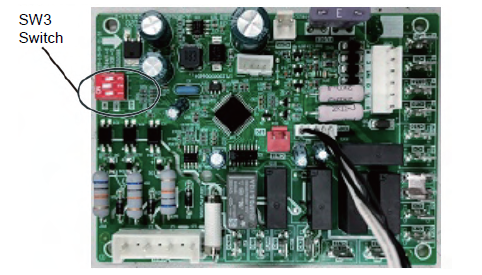
Fig.7 SW3 Switch Location in the PCB Board(For reference only)
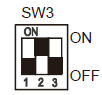
| SW3-1 | ON | MANUAL DEFROST |
| OFF | AUTOMATIC DEFROST | |
| SW3-2 | ON | INTELLIGENT DEFROST |
| OFF | NORMAL DEFROST | |
| SW3-3 | ON | DEFROSTING CYCLE:60MIN |
| OFF | DEFROSTING CYCLE:30MIN |
When SW3-3 switch is set to “OFF”(See in Fig 7), the system will perform a defrost cycle in any of the following conditions:
- If the compressor is operating and T3 is < 30.2 °F, the system will perform a defrost cycle every 60 minutes of operation.
- When T3 is < 28.4 °F and the compressor is operating for the first time after being connected power.
- When T3 is < 28.4 °F and the system has been in standby for two hours .
Shut-down conditions of defrost mode:
The mode will shut down in any of the following conditions:
- The defrosted time lasting for 10 minutes;
- T3 is ≥ 77 °F when T4 ≥ 28.4 C;
- Compressor stop operating;
- T3 is ≥ 77 °F last for 60s when T4 < 28.4 C.
THERMOSTAT SIGNALS
Table 8-1: Thermostat Signals
| Signal | State | Board Function | |
| G | ON | Blower instant ON | |
| OFF | Blower 90 sec. delay OFF | ||
| G & W1 | ON | Blower instant ON Heater bank 1 elec.onstant ON | |
| OFF | Heater bank 1 elec.instant OFF Blower 90 sec. delay OFF | ||
|
G & W & W2 | ON | Blower instant ON Heater 1 instant ON Heater 2 instant ON | |
| OFF | Blower 90 sec. delay OFF Heater 1 instant OFF Heater 2 instant OFF | ||
| G & Y | ON | Blower instant ON Compressor and outdoor fan instant ON | |
| OFF | Compressor and outdoor fan instant OFF Blower fan delay 90 sec. OFF | ||
|
G & B & Y | ON | Blower instant ON Compressor and outdoor fan instant ON 4-way valve instant ON | |
| OFF | Compressor and outdoor fan instant OFF Blower fan delay 90 sec. OFF 4-way valve instant OFF | ||
|
G & B | ON | Blower instant ON Compressor and outdoor fan instant ON 4-way valve instant ON Heater 1 instant ON | |
| & Y & W1 | |||
| OFF | Blower fan delay 90 sec. OFF Compressor and outdoor fan instant OFF 4-way valve instant OFF | ||
| Heater 1 instant OFF | |||
| Blower instant ON Compressor and outdoor fan instant ON | |||
| ON | 4-way valve instant ON | ||
| Heater 1 instant ON | |||
| G & B & Y | |||
| Heater 2 instant ON | |||
| & W1 & W2 | |||
| Blower fan delay 90 sec. OFF Compressor and outdoor fan instant OFF | |||
| OFF | 4-way valve instant OFF | ||
| Heater 1 instant OFF | |||
| Heater 2 instant OFF |
OPERATION CHECK-UP
- Cooling Startup
- Turn thermostat to OFF and turn power to ON
- Turn ON thermostat and set as high as possible
- Turn Fan switch ON and indoor blower should run
- Turn fan switch to AUTO, system switch to COOL and thermostat tem perature setting below room temperature.
Unit should run in COOLING mode.
- Heating Startup
After normal cooling run- Turn thermostat switch to HEAT. After unit stops, wait about 5 minutes.
- Turn thermostat setting above room temperature.
Unit should run in HEATING mode.
After unit has run for a while, check the following: - Are fans running properly?
- Is compressor running correctly?
- Check refrigerant change.
- Check duct connection and leaks.
- Check tubing and sheet metal rattles.
(See Wiring Diagram for electric connection detail.)
TROUBLE SHOOTING
WARNING
Components trouble shooting requires opening control box with power on. Use extreme care while working on this condition. Check nameplate and this instruction when making wire connections.
NOTE
When the outdoor temperature is between 50°F and 67°F, the compressor can only run for cooling within a short time, otherwise it may cause damage to compressor.
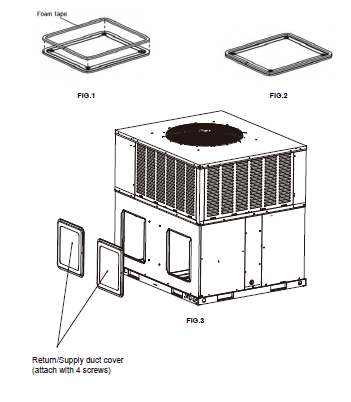
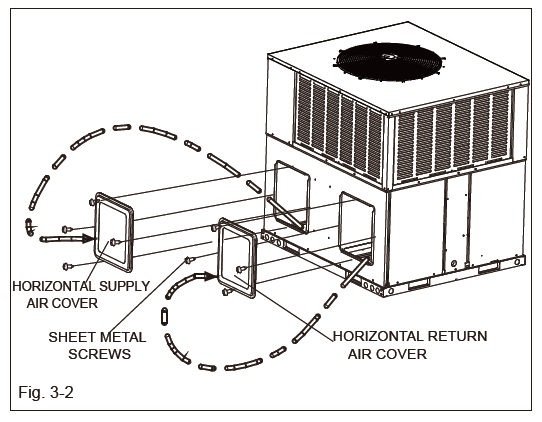
ILLUSTRATION FOR COVERING SIDE OPENINGS FOR DOWNFLOW APPLICATION
FOAM STICKED METHOD:
- Use two covers from bottom openings to cover the side openings.
- Use four sticking foam tapes provided in accessory bag and stick tapes on covers. See FIG.1 and 2.
- Place the covers on supply and return openings and use screws and washers provided to hold covers. See FIG.3.
- Use silicon sealant to seal four sides of covers to prevent water from coming into equipment.