![]()
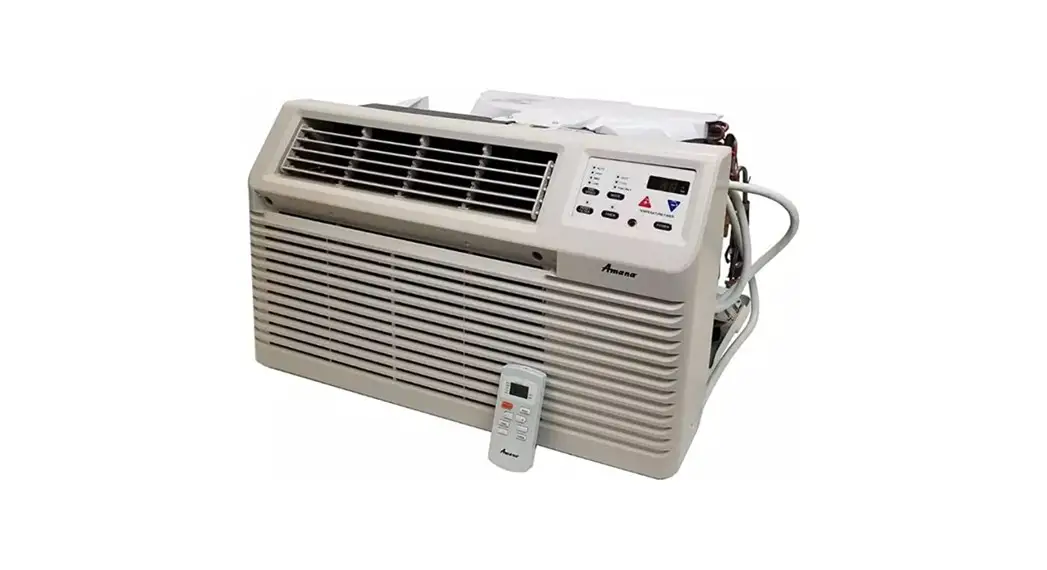
PACKAGE TERMINAL
AIR CONDITIONER/HEAT PUMP
Installation Instructions & Owner’s Manual
Standard and Remote Applications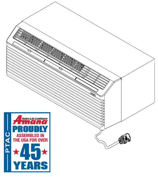
Package Terminal Air Conditioner Heat Pump
ATTENTION INSTALLING PERSONNEL
As a professional installer you have an obligation to know the product better than the customer. This includes all safety precautions and related items.
Prior to actual installation, thoroughly familiarize yourself with this Instruction Manual. Pay special attention to all safety warnings.
Often during installation or repair it is possible to place yourself in a position which is more hazardous than when the unit is in operation.
This manual must be left with the owner of the equipment.![]() WARNING
WARNING
ONLY PERSONNEL THAT HAVE BEEN TRAINED TO INSTALL, ADJUST, SERVICE OR REPAIR(HEREINAFTER, “SERVICE”) THE EQUIPMENT SPECIFIED IN THIS MANUAL SHOULD SERVICE THE EQUIPMENT. THE MANUFACTURER WILL NOT BE RESPONSIBLE FOR ANY INJURY OR PROPERTY DAMAGE ARISING FROM IMPROPER SERVICE OR SERVICE PROCEDURES. IF YOU SERVICE THIS UNIT, YOU ASSUME RESPONSIBILITY FOR ANY INJURY OR PROPERTY DAMAGE WHICH MAY RESULT. IN ADDITION, IN JURISDICTIONS THAT REQUIRE ONE OR MORE LICENSES TO SERVICE THE EQUIPMENT SPECIFIED IN THIS MANUAL, ONLY LICENSED PERSONNEL SHOULD SERVICE THE EQUIPMENT. IMPROPER INSTALLATION, ADJUSTMENT, SERVICING OR REPAIR OF THE EQUIPMENT SPECIFIED IN THIS MANUAL, OR ATTEMPTING TO INSTALL, ADJUST, SERVICE OR REPAIR THE EQUIPMENT SPECIFIED IN THIS MANUAL WITHOUT PROPER TRAINING MAY RESULT IN PRODUCT DAMAGE, PROPERTY DAMAGE, PERSONAL INJURY OR DEATH.
This device, which was assembled by Daikin Comfort Technologies Manufacturing, L.P., contains a component that is classified as an intentional radiator. This intentional radiator has been certified by the
FCC: FCC ID TF7M90-1000. And this international radiator has an Industry Canada ID: IC 27830-M90IC1000.
And this device meets the applicable Industry Canada technical specifications.
The manufacturer of the intentional radiator (model no. M90H or M90S) or FCC ID: TF7M90-1000 is Everex Communications Inc, which can be contacted by (510)-687-0075 (www.everexcomm.net).
This device complies with Part 15 of the FCC’s Rules. Operation of this device is subject to two conditions:
(1) This device may not cause harmful interference; and
(2) This device must accept any interference received, including interference that may cause undesirable operation.
And this device meets the applicable Industry Canada technical specification.
The FCC responsible party is Daikin Comfort Technologies Manufacturing, L.P. , and may be contacted by calling 713-861-2500, or at 19001 Kermier Rd., Waller TX 77484. (www.DaikinComfort.com)
This equipment complies with FCC radiation exposure limits. To ensure compliance, human proximity to the antenna shall not be less than 20 cm during normal operations.
![]() WARNING
WARNING
CHANGES OR MODIFICATIONS NOT EXPRESSLY APPROVED BY THE PARTY RESPONSIBLE FOR COMPLIANCE COULD VOID THE USER’S AUTHORITY TO OPERATE THE EQUIPMENT.
NOTE: This equipment has been tested and found to comply with the limits for a Class B digital device, pursuant to part 15 of the FCC Rules. These limits are designed to provide reasonable protection against harmful interference in a residential installation. This equipment generates, uses and can radiate radio frequency energy and, if not installed and used in accordance with the instructions, may cause harmful interference to radio communications. However, there is no guarantee that interference will not occur in a particular installation. If this equipment does cause harmful interference to radio or television reception, which can be determined by turning the equipment off and on, the user is encouraged to try to correct the interference by one or more of the following measures:
- Reorient or relocate the receiving antenna.
- Increase the separation between the equipment and receiver.
- Connect the equipment into an outlet on a circuit different from that to which the receiver is connected.
- Consult the dealer or an experienced radio/ TV technician for help.
IMPORTANT NOTE TO THE OWNER
This manual is to be used by qualified, professionally trained HVAC technicians only. Goodman does not assume any responsibility for property damage or personal injury for improper service procedures or services performed by an unqualified person.
This appliance is not intended for use by persons (including children) with reduced physical, sensory or mental capabilities, or lack of experience and knowledge, unless they have been given supervision or instruction concerning use of the appliance by a person responsible for their safety.
Children should be supervised to ensure that they do not play with the appliance.
NOTE: Maximum allowable pressures for the low-pressure and high-pressure side of the refrigeration system are 223 PSIG and 669 PSIG respectively. This unit is IPX4 rated.
Remember, it is your responsibility to install the product safely and to know it well enough to be able to instruct a customer in its safe use.
Safety is a matter of common sense…a matter of thinking before acting. Most dealers have a list of specific good safety practices… follow them.
The precautions listed in this Installation Manual are intended as supplemental to existing practices. However, if there is a direct conflict between existing practices and the content of this manual, the precautions listed here take precedence.
IMPORTANT NOTE TO THE SERVICER
Read this manual and familiarize yourself with the specific items which must be adhered to before attempting to service this unit. The precautions listed in this Installation Manual are intended as supplemental to existing practices. However, if there is a direct conflict between existing practices and the content of this manual, the precautions listed here take precedence.![]() RECOGNIZE THIS SYMBOL AS A SAFETY PRECAUTION.
RECOGNIZE THIS SYMBOL AS A SAFETY PRECAUTION.
![]() WARNING
WARNING HIGH VOLTAGE
DISCONNECT ALL POWER BEFORE SERVICING OR INSTALLING THIS UNIT. MULTIPLE POWER SOURCES MAY BE PRESENT. FAILURE TO DO SO MAY CAUSE PROPERTY DAMAGE, PERSONAL INJURY OR DEATH.
UNIT FEATURES
This unit has many features which are different than those found on conventional PTAC units. The servicer must be familiar with these features in order to properly service the unit.
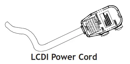
- LCDI Power Cords – Underwriters Laboratories and the National Electric Code (NEC) now require power cords that sense current leakage and can open the electrical circuit to the unit on units rated at 250 volts or less. In the event that unit does not operate, check the reset button located on or near the head of the power cord as part of the normal troubleshooting procedure.

- Automatic 3-minute compressor lockout – After the compressor cycles off, it will not restart for three minutes.
- Automatic 2nd stage electric heat – If the room temperature falls to 4°F below the set point temperature, the reverse cycle heat is shut off and the electric strip heat is turned on.
- Automatic freeze protection – Whenever power is supplied to the unit and the master switch is in the ON position, automatic freeze protection is active. If the unit senses temperature below 40°F, the fan motor and electric strip heat are turned on. Freeze protection can be turned off, if required.
- Random restart delay – To help eliminate power surges after a power outage, the unit is equipped with a two to four minute random restart delay feature. Whenever the unit is plugged in with the master switch turned on and the mode switch set in the cool or heat mode, a random restart will occur. A random restart condition can be avoided by setting the mode switch in the fan only or off position before applying power to the unit.
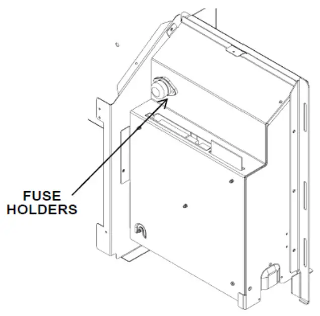
- Fuse holder – On all 265 volt units, fuse holders are factory installed. Check for blown fuse if unit does not operate. Fuse holder is located behind the front. Replacement fuses may be purchased from the Parts Department or contact your sales representative for part numbers.

Control Panel
- Indication LEDs – The controal board has LEDs that indicate board status and Error code. The LED is visible from the top left of the unit when the front cover is remeoved. Refer to the Error Table for LED status and Diagonostics.
- Load shedding – When input terminals have been configured for load shedding operations. If at any time a switch is closed between the IN1 and COM or IN2 and COM terminals as configured, the compressor and electric heater will lockout until the switch is opened.
- Transfer fan – The control board allows for an external (transfer) fan connection.
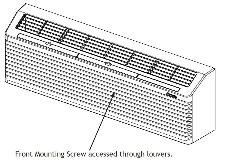
- Front mounting hole – A mounting hole location is provided to give the owner the option of securing the front to the chassis. The mounting hole must be drilled at the dimple indicating the correct location below a louver. The owner must supply one 1/2 inch long #8 sheet metal screw per unit. The screw must be removed before the front can be removed.
Chassis Front
| Goodman Part number | Manufacturer’s Part number | Usage (ref) |
| A3410402 | SLC015 | 15 AMP |
| A3410403 | SLC020 | 20 AMP |
| A3410404 | SLC025 | 25 AMP |
| A3410405 | SLC030 | 30 AMP |
Fuse Part Numbers
- Energy Management System Features
Temperature Setback – This option can save energy dollars for unrented or unoccupied rooms by automatically setting back the operational temperatures. This mode of
operation is selected through the configuration routine (see Configuration Settings section). NOTE: Temperature setback does not work with a wired remote thermostat.
Door Switch and Motion Sensor Low Voltage Terminals (IN1, IN2, COM) – The door switch and motion sensor operate as a unit, the terminals allow for wired connection of a door sensor to the control board. The motion sensor interprets any door movement as a signal of occupancy. If the switch between IN* and COM is closed, the door control will interpret the room door as closed. If the switch between IN* and COM terminals is opened (or closed if unit is configured for normally open) the control will interpret the action as a signal of occupancy. If thirty minutes pass without any door activity, Energy Management Temperature setback activates.
TRANSPORTATION DAMAGE
All units are securely packed in shipping containers tested according to International Safe Transit Association specifications.
The carton must be checked upon arrival for external damage. If damage is found, a written request for inspection by the carrier’s agent must be made immediately.
In the event of damage, the consignee must:
- Make notation on delivery receipt of any visible damage to shipment or container.
- Notify carrier promptly and request an inspection.
- In case of concealed damage, carrier should be notified as soon as possible—preferably within 5 days.
- File the claim with the following supporting documents within the 6 month statute of limitations.
a. Original Bill of Lading, certified copy, or indemnity bond. *IN1 or IN2 as configuredb.
Original paid freight bill or indemnity in lieu thereof.
c. Original invoice or certified copy thereof, showing trade and other discounts or reductions.
d.Copy of the inspection report issued by carrier’s representative at the time damage is reported to the carrier.
The carrier is responsible for making prompt inspection of damage and for a thorough investigation of each claim. The distributor or manufacturer will not accept claims from dealers for transportation damage.
UNIT ACCESSORIES
This unit is designed for through-the-wall installation in new or existing buildings. To complete the installation of this PTAC, an insulated wall sleeve and an outdoor grille (either the stamped aluminum grille, the architectural grille or polymer grille) are required.
The chassis and the cabinet front are shipped in one carton. Optional accessories to complete a particular installation are the following:
OPTIONAL ACCESSORIES
| Power Switch Kit | Wire Harness Kit |
| Wall Sleeve Kit | Architectural Grille Kit |
| Drain Kit | Remote Escutcheon Kit |
| Filter Kit | Subbase Kit |
| Water or Steam Valve Kit | Main Duct Kit |
| Power Door Kit | Leveling Legs Kit |
| Hydronic Heat Kit | Wireless Motion Sensor |
| Wireless Door Switch | Curtain Guard Kit |
| Extra Deep Sleeves | Wall Thermostat Kit |
| Extension Duct Kit | Condensate Disposal Pump Kit |
NOTE: Consult sales literature for the appropriate voltage and amperage selections, if applicable. For additional details and illustrations of the accessories, refer to the Architect’s and Engineer’s Manual.![]() Acaution
Acaution
ONLY FACTORY SUPPLIED KITS MAY BE INSTALLED WITH CONNECTIONS TO THE HIGH VOLTAGE CIRCUITS OF THE PRODUCT.
INSTALLATION INSTRUCTIONS
To ensure that the unit operates safely and efficiently, it must be installed, operated and maintained according to these installation and operating instructions and all local codes and ordinances or, in their absence, with the latest edition of the National Electric Code. The proper installation of this unit is described in the following sections. Following the steps in the order presented should ensure proper installation. Rated performance is achieved after 72 hours of operation.![]() WARNINING
WARNINING![]() HIGH VOLTAGE
HIGH VOLTAGE
DISCONNECT ALL POWER BEFORE SERVICING. – MULTIPLE POWER SOURCES MAY BE PRESENT. FAILURE
TO DO SO MAY CAUSE PROPERTY DAMAGE, PERSONAL INJURY OR DEATH. DO NOT SERVICE THIS UNIT WITHOUT FIRST ENSURING THAT:
THE ELECTRICAL ACCESSORIES ARE INSTALLED ONLY IN THE PRE-DRILLED MOUNTING HOLES.
THE ELECTRICAL WIRING IS NOT INSTALLED AND DOES NOT HANG BELOW THE PRE-DRILLED MOUNTING HOLE OR LIE IN THE UNIT BASE PAN.
SLEEVE STIFFENER AND REAR CLOSURE PANEL REMOVAL
Before the chassis can be installed in the wall sleeve, the sleeve stiffener and the rear closure panel must be removed.
- Remove the zigzag folded cardboard sleeve stiffener.
- Remove the rear enclosure panel by folding the four flaps.
- Grasping the top and bottom flanges of the rear enclosure panel pull the entire panel out diagonally from one side.
DRAIN KIT INSTALLATION (OPTIONAL ACCESSORY)
During normal reverse cycle heating operation, condensate water will drain out of the rear of the wall sleeve. If this water is objectionable, a drain kit should be installed. The drain kit has provisions for draining the water from either the right or left side of the sleeve externally or from the bottom of the sleeve internally. The drain kit must be installed before the outdoor grille is installed. Refer to the Installation Instructions supplied with the drain kit for a complete description of the installation procedure.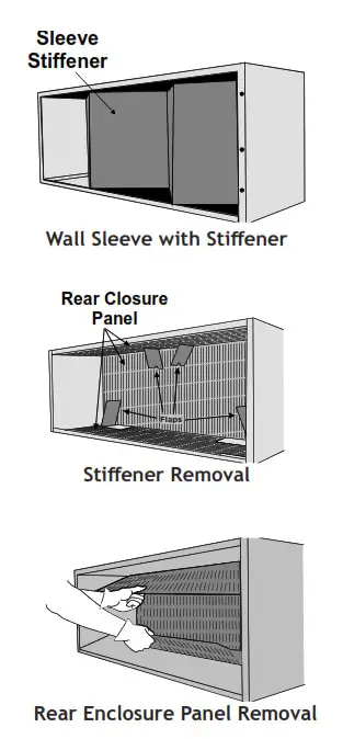
![]() WARNING
WARNING![]() HIGH VOLTAGE
HIGH VOLTAGE
DISCONNECT ALL POWER BEFORE SERVICING.
MULTIPLE POWER SOURCES MAY BE PRESENT. FAILURE TO DO SO MAY CAUSE PROPERTY DAMAGE, PERSONAL INJURY OR DEATH. DO NOT SERVICE THIS UNIT WITHOUT FIRST SHUTTING OFF POWER TO THE UNIT FROM THE CIRCUIT BREAKER AND/OR REMOVING THE UNIT CORD SET PLUG FROM THE WALL OUTLET.
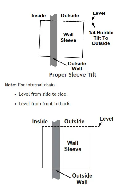
SLEEVE INSTALLATION
In order for condensate water to drain properly inside the unit, the sleeve must be installed properly:
Note: For external drain
- Level from right to left.
- A slight downward pitch from the indoor side to the outdoor side as shown below.
Refer to the Installation Instructions supplied with the PTAC wall sleeve for a complete description of the installation procedure.
OUTDOOR GRILLE
An outside grille must be installed to direct air flow for proper unit operation and also protect the outdoor coil. The grille must be installed before installing the chassis. Refer to the Installation Instructions supplied with the outdoor grille kit for a complete description of the installation procedure.
This model requires either a Stamped Grille Kit (Model SGK–B), a Polymer Grille Kit (Model PGK) or an Architectural Grille Kit (Model AGK–B). When replacing an old chassis with an existing grille or using a specialized grille in a new installation, please check with your sales representative to determine if the new chassis should be used with the non-standard specialized grille. An improper outdoor grille can decrease cooling or heating capacity, increase energy usage and shorten compressor life and possibly void the warranty.
FRONT REMOVAL
- Grasp the cabinet front.
 Cabinet Front Removal View 1
 - Pull the bottom of the cabinet front away from the chassis until the retaining clips disengage. NOTE: If front is secured with a screw, remove front mounting screw, then follow front removal procedure.

- Lift the cabinet front off the chassis. Reverse this procedure to reinstall the cabinet front.
 Cabinet Front Removal View 1
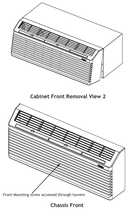
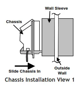
CHASSIS INSTALLATION
- Remove the cabinet front from the chassis as described in Front Removal.
- Insert the chassis into the wall sleeve.

- Slide the chassis into the wall sleeve until the chassis flanges contact the front edge of the wall sleeve.

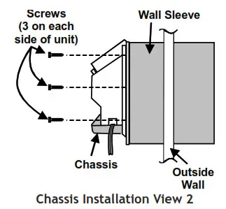
- Secure the chassis to the wall sleeve using three screws on each side of the chassis to ensure a proper seal between the chassis and the wall sleeve. The screws are supplied in a plastic bag attached to the power cord.
IMPORTANT NOTES:
- The unit is equipped with a rubber grommet mounted compressor. These grommets are factory set and require no adjustment.
- If a standard subbase is used, be sure the right hand subbase cover is removed before the chassis is installed in the sleeve.
- On 230V, 30A units installed with an existing subbase, use the subbase cover extension kit.
- Check the indoor and outdoor grilles for obstructions to air flow. The unit must be located where curtains, furniture, trees, or other objects do not block the air flow to and from the unit. If air is obstructed and/or deflected back into the unit, the air conditioner compressor may cycle on and off rapidly. This could damage the compressor or possibly void the warranty.
![]() WARNING
WARNING![]() DO NOT ALTER POWER CORD.
DO NOT ALTER POWER CORD.
DO NOT REMOVE LCDI OR AFCI CIRCUIT BOARD.
DO NOT REPLACE TERMINALS OR OTHER PARTS OF CORD.
DO NOT USE CORD IF DAMAGED.
CONTACT SERVICE PARTS FOR A REPLACEMENT CORD, IF NEEDED.![]() warnin
warnin
UNIT MAY ONLY SE HARD WIREO WITH A FACTORY SUPPLIED KIT.![]() caution
caution
TO AVOID PROPERTY DAMAGE, PERSONAL INJURY OR DEATH DUE TO ELECTRICAL SHOCK, DO NOT USE AN EXTENSION CORD WITH THIS UNIT,![]() caution
caution
TO AVOID THE RISK OF PROPERTY DAMAGE, PERSONAL INJURY OR FIRE, USE ONLY COPPER CONDUCTORS.![]() caution
caution
TO AVOID THE RISK OF PROPERTY DAMAGE, PERSONAL INJURY OR FIRE, DO NOT INSTALL WITH POWER CORD STRETCHED OR UNDER A
STRAIN AS THIS MAY CREATE A LOOSE PLUG/RECEPTACLE CONNECTION.![]() CAUTION
CAUTION
To AVOID THE RISK OF PERSONAL INJURE WIRING TO THE UNIT MUST BE PROPRERLY POLARIZED AND GROUNDED.
Cord connection to a wall socket is not permitted for 265-volt units. All 265-volt units must be hard wired using the hard wire kit or make use of the plug-in receptacle in the standard subbase. 230/208V and 115V units are equipped with LCDI or AFCI power cords and can open the electrical circuit to the unit. In the event the unit does not operate, check the reset button located on or near the head of the power cord as part of the normal troubleshooting procedure.![]() WARNING
WARNING
THIS AIR CONDITIONER IS NOT MEANT TO PROVIDE UNATTENDED COOLING OR LIFE SUPPORT FOR PERSONS OR ANIMALS WHO ARE UNABLE TO REACT TO THE FAILURE OF THIS PRODUCT.
THE FAILURE OF AN UNATTENDED AIR CONDITIONER MAY RESULT IN EXTREME HEAT IN THE CONDITIONED SPACE CAUSING OVERHEATING OR DEATH OF PERSONS OR ANIMALS.
PRECAUTIONS MUST BE TAKEN TO WARN OFF OR GUARD AGAINST SUCH AN OCCURRENCE.
HEATERLESS UNITS
If a heaterless unit is ordered, field provisions must be made for adding supplemental heat. Refer to the Installation Instructions supplied with the kit for a complete description of the installation procedures. All 208/230 volt heaterless units are shipped with a 15 Amp power cord.
VOLTAGE MEASUREMENTS
Once the unit is properly wired, measure the unit supply voltage. Voltage must fall within the voltage utilization range given in Table 2.
| Operating Voltage | ||
| Unit Voltage | Voltage Utilization Range | |
| Rating | Minimum | Maximum |
| 230/208 | 197 | 253 |
| 265 | 238 | 292 |
| 115 | 103.5 | 126.5 |
OPERATING INSTRUCTIONS
THERMOSTAT SETTING
Wired Thermostat Control
A wired wall thermostat can be connected to the unit. See section on wired inputs and unit configuration for more details. Wireless Thermostat Control
Temperature and switching off/on by fan can be controlled by the bluetooth.
LCDI
230/208V and 115V units are equipped with LCDI cords and can open the electrical circuit to the unit. In the event the unit does not operate, check the reset button located on or near the head of the power cord as part of the normal troubleshooting procedure.
DIAGNOSTIC LIGHT
The Red/Green LED light located in the upper left-hand corner of the control area as viewed from the top right of the PTAC through the control box front slot indicates a host of error codes as shown in the table below. Additionally, the blue light indicates binding and pairing conditions shown below. The most informative tool for debug, however, is the Bluetooth Application which spells out conditions these lights can only blink codes to indicate. At the beginning of any debug session, it is recommended that the servicer clean the filter unless it is a new installation. For an airflow restriction, it is also recommended to clean the coils.
NOTE: If supply voltage is 208V, the connector on the primary of the transformer(s) must be moved from the 230V tap to the 208 V tap. Refer to wiring diagram on unit for details.
LED to possible Error Code Mapping
L-Long blink (2000msec)
S-Short blink (400 msec)
Q-Quarter Blink (100 msec)
B-Blip blink (30 msec)
LS^#: #- being number of short blinks following one long blink
Note- Bluetooth app will show Diagnostic Codes and Diagnostic Codes from the app are listed below
Error Generation
| GREEN / RED LED | Status | Suggested Action |
| Flashing Green-L | No PTAC issue / board powered status codes & DigiAir errors allowed | No Action |
| Flashing Green-LS | Limited PTAC operation without Fault (Front | Investigate room conditions |
| Flashing Green-LS^2 | Unit health warning (recirculation, etc.) | Perform maintenance |
| Flashing Red-LS | Failure requiring M90 replacement | Contact an Authorized Servicer to replace the M90 board. |
| Flashing Red-LS^2 | Lockout due to air restriction, refrigerant restriction, or extreme temp | Clean Filter. Examine coils. Check refrigerant. Check indoor/outdoor air restriction and recirculation. Check motors. |
| Flashing Red-LS^3 | DC motor issue | Check for proper for proper motor operation. |
| Flashing Red-LS^4 | Sensor failure (thermistor, humidity, wireless t-stat, wireless loss, etc.) | Check sensor for obvious damage. |
| Flashing Red-LS^5 | Voltage Issue (brown out, hi volt, Amp reading, etc.) | Check incoming supply for appropriate range |
| Flashing Red-LS^6 | Configuration error | Check model and PTAC alignment |
| Flashing Red-Q | Firmware corrupted | Cycle power; replace board if necessary |
| BLUE LED | Status | Suggested Action |
| Flashing Blue-Q | No EC1 Connected | Contact Hotelier; install repeater; power on Eden control |
| Flashing Blue-L | Joined EC1 Network | No action necessary |
| Flashing Blue-LQ | Packets being received from EC1 | No action necessary |
| Flashing Blue-B | Bluetooth binding in process | Normal operation when binding to phone |
| Solid Blue | Bluetooth device bound | Normal operation |
| Flashing Blue-S | RF 802.15.4 Mesh binding in process | Normal operation when binding to wireless peripheral device |
| Flashing Blue-S^2 | Binding, T-stat bound | Normal operation |
| Flashing Blue-S^3 | Binding, Occupancy Sensor bound | Normal operation |
Errors
| Code | Status LED (Red/Grn) | Wireless LED (BLUE) | Status / Issue | Suggested Action |
| A1 | Flashing Green-L | n/a | Alarm (NO) on IN1 or IN2 Terminal | Can be normal operation. See configuration of u8 and u9. |
| A2 | Flashing Green-L | n/a | Alarm (NC) on IN1 or IN2 Terminal | Can be normal operation. See configuration of u8 and u9. |
| br | Flashing Red-LS^5 | n/a | Brown out | Check for incoming power at correct voltage. |
| C1 | Flashing Red-LS^2 | n/a | Hyd coil freeze protection | Clean filter, Check for fan and blower operation, Check for Refrigerant loss or Restricted capillary tube. |
| C2 | Flashing Green-LS^2 | n/a | Indoor recirculation | Clean Filter or Remove Air Blockage or Close Vent Door or Improve indoor to outdoor seal. |
| C4 | Flashing Red-LS^2 | n/a | Frozen ID coil | Clean filter, Check for fan and blower operation, Check for Refrigerant loss or Restricted capillary tube. |
| C5 | Flashing Green-LS^2 | n/a | Outdoor recirculation | Check for Blocked Outdoor Air or Clean Coil. |
| d5 | Flashing Red-LS^3 | n/a | OD DC Motor Issue | Check connections between outdoor motor and motor control daughter board; Replace motor and/or control if required. |
| d6 | Flashing Red-LS^3 | n/a | ID DC Motor Issue | Check connections between indoor motor and motor control daughter board; Replace motor and/or control if required. |
| Ec | Flashing Red-LS^6 | n/a | Relay Configuration Error | Confirm configuration codes P3, P4, P5, & P6 are set correctly. |
| EH | Flashing Green-LS^1 | n/a | Emergency. Hydronic | Open front desk emergency hydronic switch to allow occupant unit operation. |
| Eo | Flashing Red-LS^6 | n/a | Service Board | Enter Configuration Menu and set “C3” to “C” for coolers with electric heat or “H” for heat pumps. |
| F1 | Flashing Red-LS^4 | n/a | IAT & RIAT Sensor bad | Replace black Indoor Ambient Thermistor or Wireless Remote Thermostat |
| F2 | Flashing Red- LS^4 | n/a | T-stat Sensor bad | Replace Wireless Thermostat |
| F3 | Flashing Red-LS^4 | n/a | IAT Sensor bad | Replace Indoor Ambient Thermistors |
| F4 | Flashing Red-LS^4 | n/a | ICT Sensor bad | Replace Indoor Thermistors |
| F5 | Flashing Red-LS^4 | n/a | Wireless device signal loss | Attempt to rebind Wireless Thermostat or Replace Wireless Thermostat. |
| F6 | Flashing Red-LS^4 | n/a | IDT Sensor bad | Replace Indoor Thermistors |
| F7 | Flashing Red-LS^4 | n/a | OCT Sensor bad | Replace Outdoor Thermistors |
| F8 | Flashing Red-LS^4 | n/a | OAT Sensor bad | Replace Outdoor Thermistors |
| F9 | Flashing Red-LS^4 | n/a | CDT Sensor bad (old IHD) | Replace Outdoor Thermistors |
| FE | Flashing Red-LS^4 | n/a | CST Sensor Bad | Replace Outdoor Thermistors |
| FA | Flashing Green-L | n/a | DigiAir suction cold | Check Ventilation kit air flow for an obstruction; Check kit filter; Check for Kit refrigeration loss |
| Fb | Flashing Red-LS^4 | n/a | Low Battery | Replace Batteries in Wireless Devices. |
| FC | Flashing Red-LS^4 | n/a | DST Sensor bad | Replace DigiAir Thermistors |
| Fd | Flashing Green- LS^1 | n/a | Front Desk | Open front desk switch to allow occupant unit operation. |
| FH | Flashing Red-LS^4 | n/a | DDT Sensor bad | Replace DigiAir Thermistors |
| Fh | Flashing Red-LS^4 | n/a | OD %RH Sensor bad | Check humidity sensor connection to daughter board and replace humidity sensor if required. |
| Of | Flashing Red-LS^4 | n/a | OAT on OD RH Sensor bad | Check humidity sensor connection to daughter board and replace humidity sensor if required. |
| FP | Flashing Green- LS^1 | n/a | Room Freeze Protection | No Action required. This setting will disengage when the room temperature rises above 43°F. |
| H1 | Flashing Red-LS^5 | n/a | High Voltage | Check for incoming power at correct voltage. |
| H2 | Flashing Green-LS^2 | n/a | Hot compressor discharge | Check for fan and blower operation. Check indoor and outdoor airflow is unobstructed |
| H4 | Flashing Red-LS^2 | n/a | Hot compressor discharge | Check for fan and blower operation. Check indoor and outdoor airflow is unobstructed |
| HA | Flashing Green-L | n/a | DigiAir discharge hot | Check Ventilation kit air flow for obstruction; Check kit filter Check for proper refrigerant charge and/or leaks Check for excessive head pressure |
| HP | Flashing Green- LS^1 | n/a | Room Heat Protection | No Action required. This setting will disengage if the room temperature falls. |
| L3 | Flashing Red-LS^2 | n/a | Frosting indoor coil | Clean the filters Check coils for damage or blockage. Check airflow, check discharge check motors, check refrigerant. Check operational mode—cold outside and inside. |
| L4 | Flashing Red-LS^2 | n/a | Too hot indoor coil in heat | Clean the filters Check coils for damage or blockage. Check airflow, check discharge check motors, check refrigerant. Check operational mode—hot outside and inside. Could be a fire. |
| L5 | Flashing Green- LS^1 | n/a | Load Shedding | Open load shedding switch to allow occupant unit operation. |
| L6 | Flashing Red-LS^2 | n/a | Electric discharge too hot | Clean Filter or Remove Air Blockage. |
| L7 | Flashing Green-L | n/a | DigiAir refrigeration issue | Check Ventilation kit air flow for an obstruction; Check kit filter |
| LC | Flashing Red-LS^2 | n/a | OD Coil Hot Lockout | Clean Condenser Coils, Check Fan for fault. Code will reset after cleaning. |
| LE | Flashing Green- LS^1 | n/a | OD Coil Frosted Lockout | Can be normal operation in low outside ambient. |
| LF | Flashing Green- LS^1 | n/a | OD Coil Frost Lockout | Can be normal operation in low outside ambient. |
| LH | Flashing Red-LS^6 | n/a | (C3) Configuration Error | Check for model to physical unit alignment in configuration (C3). |
| oP | Flashing Green- LS^1 | n/a | Open door lockout | Close Room Door. Unit will not condition space with door open. |
| Ur | Flashing Green- LS^1 | n/a | Unrented Room | Front Desk needs to set to Rented mode (if applicable). |
| — | Flashing Red-LS | n/a | Program error | Contact Goodman for new Firmware. |
| — | Flashing Green-L | n/a | Error Free | No Action Needed |
CONTAINS FCC ID: TF7M90-1000
PTH153K35PXXX
THIS DEVICE COMPLIES WITH PART 15 OF THE FCC RULES. OPERATION OF THIS DEVICE IS SUBJECT TO TWO CONDITIONS:
(1) THIS DEVICE MAY NOT CAUSE HARMFUL INTERFERENCE; AND
(2) THIS DEVICE MUST ACCEPT ANY INTERFERENCE RECEIVED, INCLUDING INTERFERENCE THAT MAY CAUSE UNDESIRABLE OPERATION.
0140P00862
NOTE: Numbers are unique for each model.
User Controls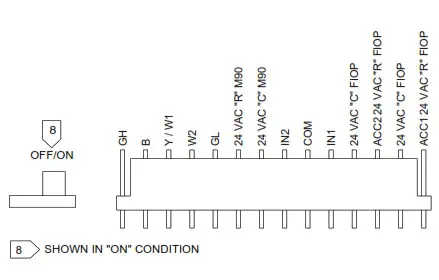 Control Board User Inputs*
*NOTE: The PTAC Wire Harness Kit (PWHK01G90) is required for the auxiliary or remote thermostat options.
ADDITIONAL CONTROL INPUTS
The control inputs shown above provide additional unit control and features. To access these control inputs, the cabinet front must be removed (see Front Removal).
MASTER SWITCH
The master switch disconnects power to all of the system components. When this switch is in the off position, the compressor, fan motor, reversing valve, and electric resistance heater will all be de-energized.![]() WARNING
WARNING![]() HIGH VOLTAGE
HIGH VOLTAGE
DISCONNECT ALL POWER BEFORE SERVICING.
MULTIPLE POWER SOURCES MAY BE PRESENT. FAILURE TO DO SO MAY CAUSE PROPERTY DAMAGE, PERSONAL INJURY OR DEATH.
DO NOT SERVICE THIS UNIT WITHOUT FIRST UNPLUGGING THE UNIT AT THE WALL OUTLET OR TURNING OFF THE POWER AT THE FUSE BOX OR CIRCUIT BREAKER. LINE VOLTAGE WILL BE PRESENT AT THE CONTROL BOARD, TERMINALS L1 AND L2, WHENEVER POWER
IS APPLIED TO THE UNIT REGARDLESS OF THE MASTER SWITCH POSITION.
REMOTE CONTROL INPUTS
The C, R, GL, W2, Y/W1, B/O, and GH terminals provide control inputs for a “manufacturer-approved” remote wall mounted thermostat. The “B” terminal can be configured to become “O” if needed see Configuration Settings For remote control thermostat operation, refer to the Remote Thermostat Operation section.
FRONT DESK CONTROL (IN1, IN2, COM)
The COM and IN2 or IN1 terminals provide control inputs for a front desk switch. Shorting across the terminals will disable unit operation. The only control function which will remain active when these terminals are shorted is freeze protection. Any switch which will produce a short circuit across these two terminals can be used as a front desk switch. The contact resistance of the switch, when closed, must be less than 200 ohms for the front desk feature to operate properly. Table 3 shows the maximum wire length and corresponding gauge size for installation of a front desk switch. The following figure shows a wiring schematic for connecting the front desk switch to the unit.
If the unit is configured for wired unrented setback energy management (see Configuration Settings section u8 and u9). If IN* and COM are shorted, the unit will go into setback temperatures for cooling and heating as configured in c3 and c4 (see Configuration Settings). Unit operation will be disabled. “Fd” (see Diagnostic Codes) will appear if the bluetooth app is used. This allows the room to quickly recover to a comfortable temperature when the room is occupied.
| Maximum Wire Length | |
| Wire Size (AWG) | Maximum Length Allowed |
| #24 | 400 ft |
| #22 | 600 ft |
| #20 | 900 ft |
| #18 | 1500 ft |
| #16 | 2000 ft |
Table 3 – Maximum Wire Length for Front Desk Switch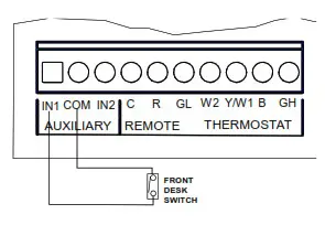 Front Desk Switch Wiring Schematic *IN1 or IN2
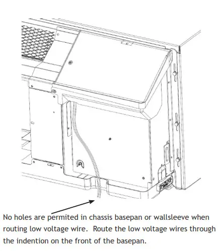
Low Voltage Wires Routing
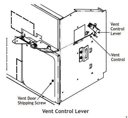
VENT CONTROL – For standard ptac models only The vent control allows outside air to be drawn into the conditioned area. This outside air can provide ventilation when the blower is operating, but it will increase the heating or cooling load and operating costs.
To obtain access to the vent control:
- Remove the cabinet front (see Front Removal).
- Remove the shipping screw (if installed) from the vent door.
- Remove the label (if present) from over the vent control lever on the left side of the chassis.
Remove the vent door shipping screw. For DigiAIR (Fresh Air Solution) kit models, refer to IO-932.
 - Rotate the vent control lever to either open or close the damper.

 For DigiAIR (Fresh Air Solution) kit models, refer to IO-932.
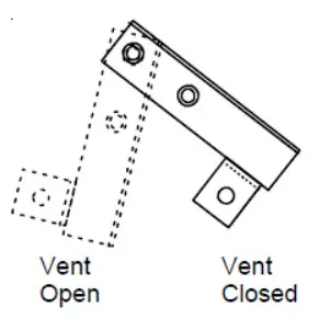
Vent Door Lever Positions
Hydronic Heat Installations
To avoid the risk of freezing the steam or water coil during prolonged shut down periods, the vent door must be left closed when the outdoor temperature might fall below freezing.
AIR DISCHARGE GRILLE
The discharge grille can be adjusted to expel air at either a 14° or 56° angle.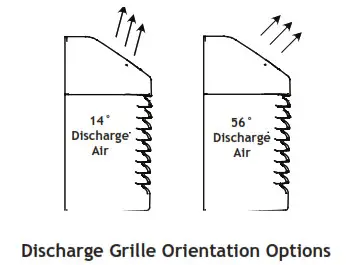
Use the following procedure to change the angle of the discharge air flow:
- Remove the front cabinet (see Front Removal).
- Position the front so that the backside is accessible.
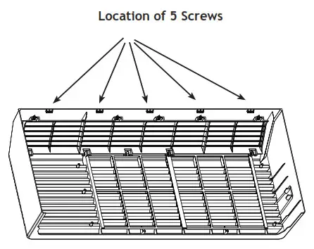
- Remove the four (4) screws which secure the discharge air grille to the cabinet front.

- Rotate the grille 180° clockwise.
- Reinstall the screws securing the discharge air grille to the cabinet front. Reinstall the cabinet front on the unit.
REMOTE THERMOSTAT
To operate this unit with a “manufacturer-approved” remote thermostat, configure the control to be operated by the remote thermostat. Enter configuration mode C1 and then select option Code L5 (see Configuration Settings in back of manual). When in the remote mode, the unit will only respond to the thermostat inputs (terminal strip positions GL (or GH), W2, Y/W1, and B* shown in “Control Board User Inputs” illustration). NOTE: Once configuration C1 with option code L5 has been selected, the room occupant must operate the unit at the remote mounted thermostat until or if a wired thermostat is connected or a service provider pairs with the bluetooth application.
NOTE: In remote mode, the 3-minute compressor time delay, the random restart feature and the freeze protection feature are all active (see Unit Features section).
THERMOSTAT LOCATION
This unit is designed to be operated with remote wall mounted thermostats. For further information on thermostats approved for use with this unit, contact your sales representative.
For best performance results, the thermostat should be located approximately five feet above the floor on a vibration free, inside wall in an area with good air circulation.
Do not install the thermostat where it may be affected by the following:
- Dead spots behind doors, in corners or under cabinets
- Hot or cold drafts from air ducts
- Radiant heat from the sun, appliances, or fireplaces
- Concealed pipes and chimneys
- NOTE: If configured, B and O input terminals can be used interchangeably.
- Unheated (uncooled) areas behind the thermostat, such as an outside walls
Consult the instruction sheet packaged with the thermostat for further details on mounting and operation.
REMOTE THERMOSTAT OPERATION
Approved thermostats vary slightly in construction and, with few exceptions, are operated similarly. The following operational description pertains to approved nonprogrammable thermostats that energize G in Heat and Cool mode.
HEAT/OFF/COOL Switch
- OFF – cooling and heating functions are defeated.
- HEAT – the selected room temperature is maintained by cycling either in the heat pump mode or electric strip heat. A PTH unit is switched from the heat pump mode to electric strip heat when the coil temperature is below 20°F or when the heat pump cannot keep up with the heating load and a two stage thermostat is used.
- COOL – the selected room temperature is maintained by cycling the air conditioner.
Table 4 summarizes the thermostat input combinations and the respective unit functions. The following wiring schematic illustrations show wiring schematics for heat pump and straight cool units with electric resistance heat, respectively.
| Unit Function | Heat Pump Thermostat Input | Electric Heat Thermostat Input | |
| R Terminal to: | R Terminal to: | ||
| OFF | NONE | NONE | |
| HEAT | Stage 1 | GL*, Y/W1, B**, O | GL* Y/W1, B**, or GL*, W2, O |
| Stage 2 | GL*, W2 | n/a | |
| COOL | GL*, Y/W1, B**, O | GL*, Y/W1 | |
*or GH depending on speed required
**If configured, B and O can be used interchangeably.
Table 4 – Remote Control Inputs
NOTE: The PTAC Wire Harness Kit (PWHK01G90) is required for remote thermostat or wireless thermostat options.
ADDITIONAL NOTES:
- For heat pump operation, a room thermostat with a B (heating change over) terminal or an O terminal (cooling change over) is required. In an “autochangeover” thermostat is to used only a Goodman approved “autochangeover” thermostat can be used, as many of them either do not have a B terminal, or else energize the B terminal continuously when in the “auto” position.
- Additional wiring should be run for future changeover to Heat Pump or thermostat options.
- Run 6 to 8 wires during initial installation. Tape or cap off any unused wires.
NOTE: Using a thermostat with an O terminal will require use of the bluetooth application.
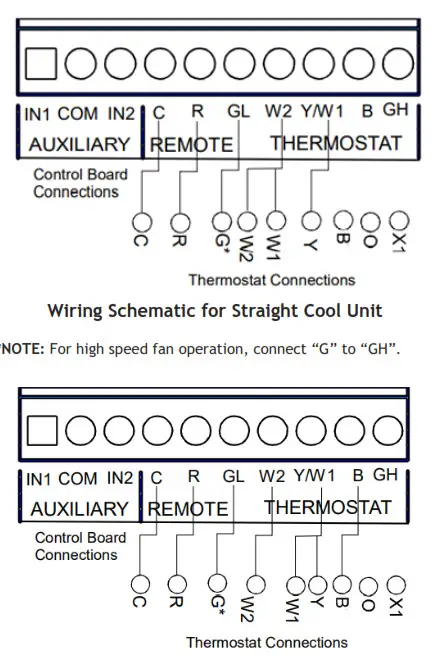
*NOTE: For high speed fan operation, connect “G” to “GH”.
Table 5 shows the maximum wire length and corresponding gage size for installation of a remote thermostat.
| Maximum Wire Length | |
| Wire Size (AWG) | Maximum Length Allowed |
| #24 | 400 ft |
| #22 | 600 ft |
| #20 | 900 ft |
| #18 | 1500 ft |
| #16 | 2000 ft |
Table 5 – Maximum Wire Length for Remote Control Connection
![]() WARNING
WARNING![]() HIGH VOLTAGE
HIGH VOLTAGE
DISCONNECT ALL POWER BEFORE CLEANING THIS UNIT.
MULTIPLE POWER SOURCES MAY BE PRESENT. FAILURE TO DO SO MAY CAUSE PROPERTY DAMAGE, PERSONAL INJURY OR DEATH.
MAINTENANCE AND CLEANING
MAINTENANCE AND CLEANING
![]() WARNING
WARNING![]() HIGH VOLTAGE
HIGH VOLTAGE
TO AVOID PROPERTY DAMAGE, PERSONAL INJURY OR DEATH DUE TO ELECTRICAL SHOCK, CLEAN AIR FILTERS AND COILS REGULARLY. CLOGGED OR SEVERELY —— RESTRICTED FILTERS OR COILS REDUCE AIRFLOW, WHICH CAN CAUSE DRASTIC EFFICIENCY LOSS AS WELL AS SEVERE COMPONENT DAMAGE TO COMPRESSORS, ELECTRIC HEATER OR FAN MOTOR. IN EXTREME CASES, CLOGGED FILTERS AND/OR COILS MAY CREATE A FIRE HAZARD AND WILL VOID THE WARRANTY![]() WARNING
WARNING
ISOME LOCAL CONDITIONS AND ENVIRONMENTS CAN CAUSE FUNGI AND OTHER MATERIAL TO GROW INSIDE THE PTAC unit. THIS MATERIAL WHEN DRIED, S$ WELL AS OTHER FOREIGN MATERIAL, SIMILAR TO DRYER LINT IN YOUR CLOTHES DRYER, ARE FIRE HAZARDS. Be sure To THOROUGHLY CHECK AND CLEAN THE UNIT’S COILS, BLOWER WHEEL AND BASEPAN PER THE INSTRUCTIONS CONTAINED IN THIS MANUAL.
MONTHLY MAINTENANCE AND CLEANING
Intake Air Filters
To properly maintain the operational performance of your PTAC unit, it is extremely important that the inlet air filters be cleaned once per month or more often if operated in dusty or dirty locations or conditions. The intake air filters are constructed of durable polypropylene. The “air intake” air filters can be easily inserted into the cabinet front using the cabinet filter guides. Before cleaning the intake filter, turn the unit off by using the thermostat. Filter should be cleaned as required.
The following procedure is used to remove the intake filters:
- Grasp each filter by its molded handle, located on the front edge of the front, below the discharge grill.
- Pull the filter straight up and remove.
- Clean filter with vacuum or with running water.
Reverse this procedure to reinstall the filters.
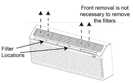
Intake Filter Removal
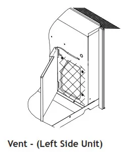
Vent Screen
Before cleaning the vent screen, disconnect power to the unit by unplugging the power cord at the wall outlet or subbase, or disconnect power at the fuse box or circuit breaker. If unit is operated with vent door closed, the vent screen does not need to be cleaned.
- Remove the cabinet front as described in Front Removal.
- Remove the six screws securing the chassis to the wall sleeve.
- Slide the chassis out of the wall sleeve far enough so that the vent screen is accessible.
- Clean the vent screen, slide the chassis back into the wall sleeve, secure it in place with six screws and reinstall the front cabinet.
Cabinet Front
NOTE: Opening size of vent is 6.79 x 5.58 inches
The cabinet front and discharge air grille can be cleaned with a water dampened cloth. Under no circumstances should hydrocarbon-based cleaners (e.g. acetone, benzene, naphtha gasoline, etc.) or ammonia based cleaners be used to clean the front or air grilles. Use care when cleaning the control area.
YEARLY MAINTENANCE AND CLEANING
NOTE: Use a mild biodegradable detergent such as Simple Green™ when cleaning the unit. Special care must be taken to protect the unit’s control board and other electrical components from getting any water on them while cleaning. The use of harsh or caustic cleaning agents or materials such as bleach or coil cleaners that are not designed for PTAC products will cause damage or deterioration of the aluminum fin or coil material and is not recommended. Care must be taken not to bend the aluminum fin stock.
Routine Scheduled Maintenance
To achieve continuing top performance and high efficiency, establish a “once a year” cleaning/inspection schedule for the unit. Take the unit out of the sleeve and thoroughly clean and rinse. Be sure to include in the yearly cleaning the evaporator coils, and condenser coils, basepan, and drain passages. Scheduled maintenance can be accomplished by either qualified local maintenance staff or by an authorized servicer. They must follow the instructions described in this manual. Adverse Operating Conditions Maintenance Units operating in dusty or corrosive locations; i.e. dusty construction site or sea coast, must be cleaned more often. A minimum of four (4) times a year will maintain proper operational conditions and protect unit components. Wall Sleeve Clean the wall sleeve while cleaning the unit. The caulking around the sleeve should be checked to make sure that any potential air and water openings around the sleeve are properly sealed. The wall sleeve’s level should also be rechecked. Proper leveling for
most installations are a ¼ bubble tilt to the outside and level from right to left. Contact your sales person for detailed maintenance or cleaning instructions.
Basepan and Condenser Coil![]() CAUTION
CAUTION
DO NOT USE COMMERCIAL GRADE COIL CLEANERS. SOME OF THESE
CLEANERS MAY CONTAIN ETHYLENE DIAMINE TETRACETIC ACID (EDTA)
WHICH CAN SHORTEN THE LIFE OF THE CONDENSER COIL.
Before cleaning the basepan and condenser coil, turn OFF unit mode switch and disconnect power to the unit. To disconnect power, either unplug the power cord at the wall outlet or subbase, or disconnect power at the fuse box or circuit breaker.
- Create a water-tight seal by tightly covering the entire control panel area and fan motor with plastic. Creating this seal prevents water from entering the control area or the fan motor and damaging the unit.
- Spray condenser coil and basepan down with water. Next spray a mild biodegradable detergent such as Simple Green™ onto the condenser coil and basepan. Let set for five (5) minutes.
- Rinse condenser coil and basepan with water again. NOTE: Ensure water pressure is no higher than that of an ordinary garden hose and the water temperature no higher than 120°F.
- Tilt the non-compressor side of the unit up no higher than 45 degrees and allow water to drain out the other side of the unit.
- Remove excess water left in the basepan by wiping the basepan with a dry cloth.
- Remove the water-tight seal from the motor and control panel area.
- Reinstall unit back into wall sleeve.
- Allow unit to dry for 24 hours before reapplying power. When power is reapplied test unit for proper operation.
- Place a non-acidic algaecide in the basepan to inhibit bacteria growth. Ensure the algaecide is compatible with wet coil operation and is not corrosive to the coil.
![]() CAUTION
CAUTION
HIGH PRESSURE AND HIGH TEMPERATURE CLEANING IS NOT RECOMMENDED.
DOING SO COULD DAMAGE THE ALUMINUM FIN STOCK AND ELECTRICAL COMPONENTS.
Clearance Check
Clearances around the unit should also be checked to make sure that the intake air and discharge air paths have not become blocked or restricted. A minimum of eight inches clearance is needed from unit to furniture , beds, or other objects for proper operation. Restricted discharge or intake air will reduce the unit’s operational performance. In severe airflow restrictions damage can occur to unit components such as the compressor, electric heater or fan motor.
OBTAINING SERVICE
In the event this unit requires repair or servicing beyond what is covered in this manual, contact an authorized service organization.
To obtain an authorized servicer, contact your sales representative or agency.
NORMAL OPERATING SOUNDS AND CONDITIONS
- Water trickling sounds
Water is picked up and distributed over the coil. This improves the efficiency and helps with water removal. - Water dripping
Water will collect in the base pan during high humidity days.
This can cause overflow and drip from the outside of the unit. - Air sounds
The fan cycle switch sets the operational mode of the fan in the ON position. The fan will run continuously whenever power is applied in this mode. In the AUTO position, the fan will cycle on and off with the compressor or electric heater. - Starting delay
You may notice a few minutes delay in the starting if you try to restart the unit too soon after turning it off or if you adjust the thermostat right after the compressor has shut off. This is due to a built in delay to protect the compressor.
PTAC CONNECT APP
Overview
PTAC Connect is the mobile app that empowers you to program, via Bluetooth, our new J/K series PTACs. The app is part of the Goodman Amana PTAC suite of apps.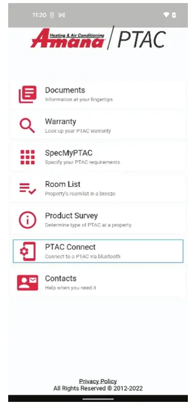
Where to get the app?
You can find our app in the Google Play Store and in the Apple App Store by simply searching for Amana PTAC. Alternatively, you can use your phone’s camera to scan
one of the below QR codes that will take you to directly to the app.
 For Android: https://play.google.com/store/search?q=Amana%20PTAC&c=apps
 For iOS: https://apps.apple.com/us/app/amana-ptac/id1485904992?platform=iphone
Making the Connection
Programming your PTAC starts with connecting the app to the PTAC device. To do so, first select PTAC Connect from the list of Amana PTAC apps above. A screen with
a scan button will appear, shown below as a red button with a magnifying glass. Next, press the physical red button on the PTAC control board, one push, do not hold
down, (PTAC control board, under the PTAC front cover and splash guard) then press the scan button in the app.
Touching this button will signal the app to scan for all Bluetooth-connectable PTACs. When found the PTAC will be listed showing the serial number as the main identifier to confirm it is the correct unit you wish to pair with. Touching the Connect button next to a desired PTAC on the list will connect the app to the PTAC.
The App’s Navigation
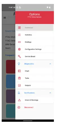
Once the app is connected to a PTAC, the app’s menu accessor ( , upper right corner) will be visible. Touching the menu accessor will show the app’s list of all available programming options:
- Dashboard
- Statistics
- Bindings
- Configuration
- Settings
- Service Board
- Diagnostics
- Notifications
If you have navigated to a screen that is not the app’s main Dashboard screen (see the section for programming screens), You will find a red return to dashboard icon under the current screen name as shown below. You can press this icon at any time to return to the Dashboard.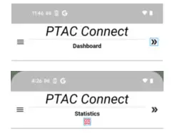
The App’s Programming Screens (or options) Dashboard
The Dashboard contains, among other things, the PTAC’s at-a-glance info (Board Info) and the most frequently used PTAC settings (Frequent Settings)
Almost everything on this screen, when touched, will display some type of additional info or an additional programming user interface (UI). Two pieces of UI are of
special consideration here: the Room setting value (next to Board Info | Room) and the Configuration icon ( , next to Frequent Settings).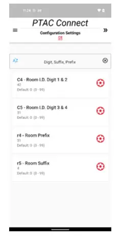 Touching the Room setting value brings up the configuration screen with the room number settings prepopulated for quick editing. From here you can set the room number your PTAC is in.
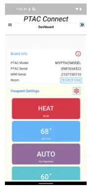
For most applications you will only need to worry about the C4 and C5 setting. The C4 setting this is commonly the “floor” your room in on. For example, if you are
programming room number 213 the C4 would be 02. The second setting is the C5 setting this is the rooms “number” for the room 213 the C5 setting would be 13. The less commonly used room number fields are the r4 and r5. The r4 is rarely used and can be safely left at 00 unless otherwise requested by a technical representative. Lastly the r5 setting this is the room suffix, this is used to distinguish between two or more units in the same room.
The unit closest to the door should be set as 01, and then next from the door as 02. This will allow you to have a room 213.01 and 213.02 so you can distin-
guish between PTAC’s during servicing and for use with the Eden Energy Management System. Touching the Configuration icon brings up the Configuration screen with all
PTAC settings. This screen can also be alternatively accessed via the menu (Menu | Configu- ration Settings).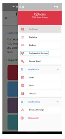
To change any setting, just touch the red gear button on the right-hand side of the setting.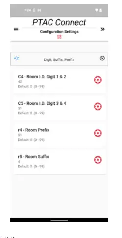
Statistics
This screen displays many useful read-only runtime info from the PTAC board such as Current Mode, Current Temperature, Setback settings, etc.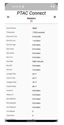
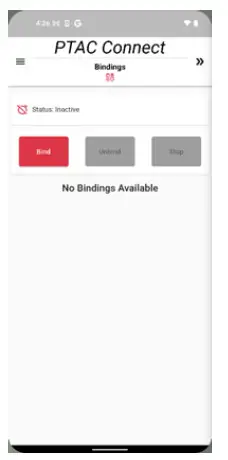
Bindings
The PTAC Connect allows you to bind or unbind a wireless peripheral such as a thermostat or an occupancy sensor.Binding or unbinding is accomplished by touching the corresponding Bind or Unbind button on this screen. You will then need to press the white binding button on the peripheral you wish to bind. If the binding fails or the device cannot be reached, you can be stop the binding search with the Stop button.
You also have the option to bind without using the app. Simply press and hold the red button (PTAC control board, under the PTAC front cover and splash guard) for
5 seconds, then press the white binding button on the peripheral you wish the bind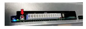
Configuration Settings
Nearly all the PTAC board’s programmable settings can be configured on this screen (except for the PTAC’s Mod- el and Serial Number, which are configured on another
screen, i.e., the Service Board screen).
If you would like to find a setting quickly the search bar will help you filter through the many settings available to you. Search terms can be case-sensitive and can be single words separated by commas. An example was shown above in the section for Dashboard, where Room settings were filtered with the search terms: Digit, Suffix, Prefix.
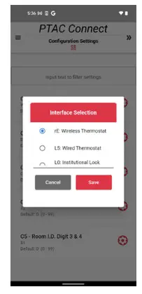
Also, as briefly introduced in the Dashboard section, to change any setting, just touch the red gear button on the right-hand side of the setting. A configuration dialog or sheet will pop up to allow the user to make a setting change.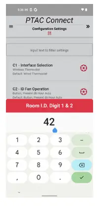
After settings changes are made, the Configuration Settings screen will display the number of settings that were edited and highlight which settings the editing was for. You will then be presented with the Save Settings button to save the changes to the PTAC board.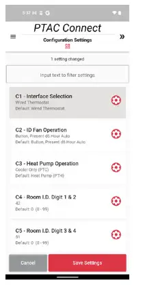
Service Board
This menu allows you to view the board’s Model and Serial Number. It also contains the Factory Reset button for your board. By selecting Factory Reset, all programmable board settings, including those in the Configuration Settings screen, will be reset to original factory values.
If you have the need to replace a control board, the board’s Model and Serial Number are available here to be configured. Before this setting is available, the C3 (Heat Pump Operation) in the Configuration Settings screen must be to Eo (Service Mode, No Operation).
Diagnostics
The Diagnostics screen allows you to see how the PTAC’s thermistors are performing. This diagnostic tool is available both graphically (in a chart) and numerically (in a table). Based on the data that is being shown when the tool runs, you can effectively diagnose how well the PTAC is running or what issues it is experiencing. Note: once the Diagnostic process starts, it is expected to display real time values while on screen. Thus, there is no Stop button available.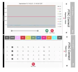
Notifications
The Notifications screen reports all errors and warnings present on the PTAC board. On this screen, there are two lists. The top shows a list of all current errors. The bottom shows all logged (historical) errors and warnings. 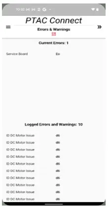
CONFIGURATION SETTINGS CHART
| Reference M70/M90 Conf. Code | Configuration Code Description | Option Code | Option Code Description | Factor y Reset |
| C1 | User Interface Selection | 0 | Reverts to L5 (Legacy Chassis Membrane) | No |
| L5 * | Wired Thermostat | |||
| rE | Wireless Stat (Self configures at binding) | |||
| L0 | Institutional Lock Wireless Thermostat | |||
|
C2 |
Fan Switch Type (ID Fan Op.) | bP | Follows (Cr) selection if any |
Yes |
| bA** | Follows (Cr) selection if any; reverts to Auto after (d6) hours | |||
| A | Fan always runs (24/7/365) | |||
| bC | Follows (Cr) selection if any; reverts to Cont. after (d6) hours | |||
| Au | Reverts to “bA” | |||
| On | Reverts to “bA” | |||
| C | Reverts to “bA” | |||
|
C3 |
Basic Unit Type | C | Cooler Only (PTC) |
No |
| H* | Heat Pump (PTH) | |||
| 0 | Service No Operation “Eo” | |||
| dC | Dry Cooler (DRY) | |||
| dH | Dry Heat Pump (DRH) | |||
| uC | Revert to option “C” | |||
| uH | Revert to option “H” | |||
| AC | Makeup Air Cooler (PMC) | |||
| AH | Makeup Air Heat Pump (PMH) | |||
| EC | High Eff. Cooler (HEC) | |||
| EH | High Eff. Cooler (HEH) | |||
| 3C | 32C Cooler (32C) | |||
| 3H | 32C Heat Pump (32H) | |||
| C4 | Room Digits 1 & 2 | 00* – 99 | 00* – 99 | No |
| C5 | Room Digits 3 & 4 | 00* – 99 | 00* – 99 | No |
| C6 | Occupancy Type (Use of wired occupancy sensor) | 0 ** | Off ** | Yes |
| 1 | On | |||
| 18 | 18 Hour Automatic entry into setbacks w/ no button op. | |||
| C7 | Motion Sensor Polarity (Normally open/closed) | 0 ** | Normally Closed ** (0 w/ occ) | Yes |
| 1 | Normally Open (1 w/ occ) | |||
| C8 | Temp limit COOLING (min) | 60** – 80 | 60** – 80 DEGF | Yes |
| C9 | Temp limit HEATING (max) | 68 – 90, 80** | 68 – 90, 80** DEGF | Yes |
| C0 | Thermostat Reversing (“B” or “O”) | b ** | “B” T-stat Terminal ** | Yes |
| 0 | “O” T-stat Terminal | |||
| c3 | Unrented Cool Setpoint | 73 – 95, 79** | 73 – 95 DEGF | Yes |
| c4 | Unrented Heat Setpoint | 45 – 67, 63** | 45 – 67 DEGF | Yes |
| CA | Wireless twinning enabled | 0 ** | Not Twinned ** | Yes |
| 5 | Twinned | |||
| Cb | Dehumid Activation (enable larger room swing) | 0 ** | Not Active ** | Yes |
| 1 | Active | |||
| U | Active in Unrented/Unoccupied | |||
| CC | Dehumid Call Drop Temp (room swing delta) | 3** – 8 | 3** – 8 DEGF | Yes |
| Cd | English/Metric Temperature (Display DEGF or DEGC) | F ** | Fahrenheit Scale ** | Yes |
| C | Celsius Scale | |||
| CE | Freeze Protection (Activation & speed selection) | L ** | Freeze Protection On, Low Fan (FP & HS) ** |
Yes |
| H | Freeze Protection On, High Fan (FP & HS) | |||
| 0 | Freeze Protection Off; Heat Sentinel Low Fan |
| CF | High Speed Fan Temp Cool (Cooling temp delta for ID fan to go to high in auto fan) | 5** – 9 | 5** – 9 DEGF | Yes |
| CH | High Speed Fan Temp Heat (Heating temp delta for ID fan to go to high in auto fan) | 6 – 8** | 6 – 8** DEGF | Yes |
| CJ | Second Stage Heat (Delta setting or disable) | 4** – 8 | 4** – 8 DEGF |
Yes |
| – – | No Elec. Heat | |||
| Cr | T-stat Fan Button (applicable only to single button thermostat) | 0 | T-stat – toggles through all 6 options Lo Auto, Lo Cont., Hi Auto, Hi Cont., Smart Auto, Smart Cont. | No |
| 1 | T-stat – Button selects Lo Cont.- Hi Cont. – Smart Auto | |||
| 2 | T-stat – Button selects Cont.- Auto Fan is in Smart Speed only | |||
| Cu | Mode Button Usage | 0 * | Off/Cool/Heat * | No |
| 1 | Off/Auto-changeover | |||
| 2 | Off/Cool/Heat/Auto-changeover | |||
| Cy | Auto-changeover Dead Band | 4 – 9, 4* | 4 – 9, 4* | Yes |
| d1 | Room Air Mix Cooling | 1 | On | Yes |
| 0 ** | Off ** | |||
| d2 | Room Air Mix Heating | 0 ** | Off ** | Yes |
| 1 | On | |||
| d3 | Air Mix Fan Speed | L ** | Low ** | Yes |
| H | High | |||
| d4 | Heating Smart Fan (“Auto” adjusting speed availability in Heating) | 0 | Not Available | Yes |
| 1 ** | Available ** | |||
| d5 | Health Warning Activation (warnings/lockouts enable) | 1 | Enable | Yes |
| 0 ** | Disabled* | |||
| d6 | Sensorless Unoccupied Time (hrs. to enter un-occupied state w/o button press) | 1 – 32, 18** | 1 – 32, 18* Hours | Yes |
| d7 | Setback 1 Value (Degrees setback in 1st setback period) | 1 – 16, 2** | 1 – 16, 2** DEGF | Yes |
| d8 | Setback 1 Time (hrs. before 1st setback period after going un-occ.) | 0.1, 0.5**, 24-Jan | 0.1 ,0.5 ,1 – 24, .5** Hours | Yes |
| d9 | Setback 2 Value (Degrees setback in 2nd setback period) | 1 – 16, 3** | 1 – 16, 3** DEGF | Yes |
| dA | Setback 2 Time (hrs. before 2nd setback period after going un-occ.) | .5, 1** – 24 | (d8) – 24, 1** Hours | Yes |
| db | Setback 3 Value (Degrees setback in 3rd setback period) | 1 – 16, 6** | 1 – 16, 6** DEGF | Yes |
| dC | Setback 3 Time (hrs. before 3rd setback period after going un-occ.) | 1 – 24, 3** | (dA) – 24, 3** Hours | Yes |
| dd | Cooling Capacity (Nominal/Unit Nomenclature) | 0, 5-24, 15* | 0 (test unit), 5,000 – 24,000 BTU, 15,000 * | No |
| dE | Demo Mode enable (shortens setback times for shows) | 0 ** | Dis-enabled ** | Yes |
| 1 | Enabled | |||
| dF | Group Code (Hotel unique platform code – multiple hotels in proximity) | 00* – 99 | 00* – 99 | No |
| dH | Electric heater size (Nominal/Unit nomenclature) | 00, 15, 20, 25, 35, 50* | 00, 15, 20, 25, 35, & 50* kW | No |
| dJ | Operating voltage (Nominal/Unit nomenclature) | 2, 3*, 4, 5 | 2, 3*, 4, 5 | No |
| dL | Selects to show (or not) actual setpoint if limiting SP | 0** or 1 | 0** or 1 | Yes |
| FA | Temp below which “FA” error code fires | 20 – 40, 30* | 20°-40°, 30°* | No |
| HA | (Temp + 200) above which “HA” error code fires | 00 – 57, 50* | 200° + {0° – 57°}, 250°* | No |
| J0 | Low Outdoor Fan Speed (Disable use of highspeed OD fan) | 0* | Disabled* | No |
| L | Enabled, No High OD Fan Op. | |||
| J1 | Factory setting (do not change); L4 Constant | 00 – 99, 60* | 100 + {0- 99}, 160* | No |
| J2 | Factory setting (do not change); L6 Constant | 00 – 99, 40* | 100 + {0- 99}, 140* | No |
| J3 | Factory setting (do not change); LC Constant | 35 – 99, 60* | 100 + {35- 99}, 160* | No |
| J4 | Factory setting (do not change); C2 Constant | 05 – 40, 14* | 5 – 40, 14* | No |
| J6 | Factory setting (do not change); C4 Constant | 50 – 99, 75* | 50 – 99, 75* | No |
| J7 | Factory setting (do not change); C5 Constant | 10 – 99, 60* | 10 – 99, 60* | No |
| J8 | Time un-rented state will revert to rented if network lost | 01 – 99, 30* | 01 – 99, 30* Minutes | No |
| J9 | Disable out of room mesh communication (in room only) | 1* | Enabled * | No |
| 0 | Dis-enabled | |||
| JA | Disables “HI” high voltage error | 1* | Enabled * | No |
| 0 | Dis-enabled | |||
| Jb | Freeze Protection Temp | 25 -55, 40* | 25 -55, 40* DEGF | No |
| JC | IAT Weight (Percentage weighting of IAT verses RIAT to room temp) | 0 – 99, 20* | 0 – 99, 20* | No |
| Jd | Offset temperature to align stat with customer’s reading | -9 – 9, 0* | -9 – 9, 0* DEGF | No |
| JF | Economizer/Smart Vent Outside Cold Limit (Coldest OD temp Economizer / Smart Vent allowed to op.) | 0 ** | 0 ** [No limit] | Yes |
| 1 – 70 | {1 – 70} -20 (55=35°F) |
| JH | Economizer/Smart Vent Outside Heat Limit (Hottest OD temp Economizer / Smart Vent allowed to op.) | 0** | 0 [No limit] | Yes |
| 60 – 99, 95 | 20 + {60 – 99}, 95 (95=115°F) | |||
|
JJ |
Electric or Hydronic Heat | 0 | Reverts to 27 |
No |
| 25-Jan | Reverts to 27 | |||
| 27* | Electric Heaters | |||
| 28 | Reverts to 27 | |||
| 29 | Hydronic (N.C. Valve) | |||
| 30 | Hydronic (N.O. Valve) | |||
| JP | Temp subtracter to 210 or 230 for “H2” & “H4” error, 0=Off | 0 ** | 0 ** | Yes |
| Jan-99 | Jan-99 | |||
| JL | PSC / DC motor usage | 0 * | ID PSC w/ Hall Effect & OD PSC Motors | No |
| 1 | ID DC Motor & OD PSC Motor | |||
| 2 | ID PSC Motor w/ Hall Effect & OD DC Motor | |||
| 3 | ID DC & OD DC Motors | |||
| Ld | (# x 10) = minutes for Lighting control op; 0=Disabled | 0 | 0 [Disabled] | Yes |
| 1-9, 3** | 10 x {1-9}; 10 x 3** = 30 Minutes | |||
|
P0 |
Selects Smart Vent op. (w/fan, w/occ., 100%, etc.) | 0 | Off |
Yes |
| 1 ** | On only when ID fan running ** | |||
| 2 | On only when ID fan running and room is occupied. | |||
| 3 | On all the time | |||
| 4 | On when room is occupied | |||
| E | Economizer (compressor locked out) | |||
| EP | Econ & compressor assist | |||
|
P2 |
Selects DigiAir op (off, unlimited, w/ fan, w/occ, etc.) | 0 | Off |
Yes |
| 1 ** | May be On Anytime ** (Kit fan is always running) | |||
| 2 | Allowed on only when not in Off mode | |||
| 3 | Allowed only when ID fan is running | |||
| 4 | Allowed on only when room is unoccupied | |||
| 5 | Allowed on only when room is occupied | |||
| 6 | Allowed only when ID humidity is higher than (ub) | |||
| 7 | Same as opt. 6; but muffin fan is always running | |||
| 8 | Allowed only when Bath Vent is running | |||
| 9 | Allowed only when Bath vent is running & Occupied | |||
|
P3 | Low Indoor PSC Motor Relay usage (Pin 4 on J504) | 0 * | PSC Low Speed Blower * |
No |
| 1 | Reverts to 0 | |||
| 3 | Reverts to 0 | |||
| 4 | Reverts to 0 | |||
| 5 | Reverts to 0 | |||
| 6 | Reverts to 0 | |||
| 7 | DigiAir Air Compressor | |||
|
P4 | High Indoor PSC Motor Relay usage (Pin 1 on J504) | 0 * | PSC High Speed Blower * |
No |
| 1 | Reverts to 0 | |||
| 2 | DigiAir Heater | |||
| 3 | Reverts to 0 | |||
| 4 | Reverts to 0 | |||
| 5 | Reverts to 0 | |||
| 6 | Reverts to 0 |
|
P5 | Low Outdoor PSC Motor Relay usage (Pin 4 on J503) | 0 * | PSC Low Speed Fan * |
No |
| 3 | Reverts to 0 | |||
| 4 | Reverts to 0 | |||
| 5 | Reverts to 0 | |||
| 6 | Condensate Pump Kit | |||
|
P6 | High Outdoor PSC Motor Relay usage (Pin 1 on J503) | 0 * | PSC High Speed Fan * |
No |
| 3 | Reverts to 0 | |||
| 4 | Reverts to 0 | |||
| 5 | Reverts to 0 | |||
| 6 | Reverts to 0 | |||
|
P7 | Acc 1 Relay usage (Pin 2 on J506, Pin 2 on J507, & Pin 1 on J200) | 0* | No Function* | |
| 1 | Makeup Air Ventilation |
No | ||
| 3 | Ventilation/Econ/Econ+, per (P0) * | |||
| 4 | Lighting Control Kit | |||
| 5 | Transfer Fan Kit | |||
| 11 | Hydronic Valve / Exterior Heater | |||
|
P8 | Acc 2 Relay usage (Pin 2 on J508, & Pin 3 on J200) | 0* | No Function* | |
| 4 | Lighting Control Kit | No | ||
| 5 | Transfer Fan Kit | |||
| 9 | Bath Vent Unique Operation | |||
| 11 | Hydronic Valve / Exterior Heater | |||
| P9 | DC Motor Quiet Speeds Enable | 0 ** | Only run Standard Speeds | Yes |
| 1 | Only run Quiet Speeds | |||
| 2 | Standard Spds in daytime; Quiet Spds in Night (EC1 only) | |||
| 3 | All Speeds based upon delta T & humidity? in Auto | |||
|
r0 |
Warning “L7” severity selection | 0 | Revert to option “1” |
Yes |
| 1 ** | L7 will evoke only a recorded code, user still able to adjust temperature settings. ** | |||
| 2 | Revert to option “1” | |||
| 3 | Complete Shutdown and Lockout. Error flash code will be evoked on Bluetooth App or Central Control. | |||
| r4 | Room Prefix | 00* – 99 | 00* – 99 | No |
| r5 | Room Suffix | 00* – 99 | 00* – 99 | No |
| u1 | Disable motion sensor on T-stat | 1 ** | Enabled ** | Yes |
| 0 | Dis-enabled | |||
|
u2 |
Allow display of room temp on T-stat; except for setting |
0 ** |
Display only Set Point ** |
Yes |
| 1 | Display Room Temp | |||
|
u3 |
Temp to engage Heat Sentinel; 0=Disabled |
0 ** |
Dis-enabled ** |
Yes |
| 78 – 99 | 78 – 99 DEGF | |||
| u4 | Open Door Shut down (Minutes door left open before shutting down) | 0 ** | Dis-enabled ** | Yes |
| 30-Jan | 1 – 30 Minutes | |||
| u5 | Time cleaning staff may override un-rented state | 0 | Dis-enabled | Yes |
| 1 – 99, 30** | 1 – 99, 30** Minutes | |||
| u7 | Compressor Lock-in Time | 4** – 10 | 4** – 10 Minutes | Yes |
| u8 | Input Pins IN1 (FD, LS, EHH, door, etc.) | 0 | Door Switch |
Yes |
| 1 | Motion Sensor | |||
| 2 ** | Front Desk ** | |||
| 3 | Wired Un-rented Set Back | |||
| 4 | Emergency Hydronic | |||
| 5 | Load Shedding | |||
| 6 | Alarm Sensor (normally open option) | |||
| 7 | Alarm Sensor (normally closed option) | |||
| 8 | Bath Vent Op. Input | |||
| 9 | Hydronic Coil Switch | |||
| u9 | Input Pins IN2 (FD, LS, EHH, door, etc.) | 0 | Door Switch |
Yes |
| 1 | Motion Sensor | |||
| 2 ** | Front Desk ** | |||
| 3 | Wired Un-rented Set Back | |||
| 4 | Emergency Hydronic | |||
| 5 | Load Shedding | |||
| 6 | Alarm Sensor (normally open option) | |||
| 7 | Alarm Sensor (normally closed option) | |||
| 8 | Bath Vent Op. Input | |||
| 9 | Hydronic Coil Switch | |||
| ub | ID humidity below which DigiAir does not run; (P2=6 must) | 0,15 – 80, 25** | 0, 15 – 80, 25** | Yes |
| uE | Room delta above Setpoint Economizer reverts to A/C | 0-50, 10** | 0-50, 10** DEGF | Yes |
| uF | Temp OD must be below Setpoint for Economizer | 0-50, 5** | 0-50, 5** DEGF | Yes |
| uH | Cooling Setpoint when exiting Un-rented state | 60 – 72** | 60 – 72** DEGF | Yes |
| uJ | Heating Setpoint when exiting Un-rented state | 74** – 90 | 74** – 90 DEGF | Yes |
| uL | Two-digit security code required to enter Configurations | 00* – 99 | 00** – 99 | No |
| un | OD humidity level above which DigiAir compressor op. | 0 | Dis-enabled | Yes |
| 15 – 60, 30** | 15 – 60, 30** | |||
| ur | Selects if DigiAir uses only single or multi- level %RH | 0 ** | DigiAir compressor engages on Steps ** | Yes |
| 1 | DigiAir compressor engages on OD %RH (un)+30 | |||
| uu | Selects if ID fan runs concurrent with DigiAir compressor | 0 ** | ID Fan runs at speed per standard logic **Everex Factory | Yes |
| 1 | ID Fan runs low with DigiAir *Goodman factory |
![]() WARNING
WARNING
IT IS ESSENTIAL THAT INDOOR AND OUTDOOR UNITS BE PROPERLY MATCHED. FAILURE TO FOLLOW THESE INSTRUCTIONS OR TO PROPERLY MATCH EVAPORATORS AND CONDENSERS CAN RESULT IN UNIT DAMAGE, PROPERTY DAMAGE AND/OR PERSONAL INJURY. NO WARRANTY CLAIM WILL BE HONORED FOR MIX-MATCHED SYSTEMS THAT FAIL TO ADHERE TO THE SPECIFIED PISTON SIZE![]() HIGH VOLTAGE!
HIGH VOLTAGE!
DISCONNECT ALL POWER BEFORE SERVICING OR INSTALLING THIS UNIT.
MULTIPLE POWER SOURCES MAY BE PRESENT. FAILURE TO DO SO MAY CAUSE PROPERTY DAMAGE, PERSONAL INJURY OR DEATH.
CUSTOMER FEEDBACK
We are very interested in all product comments.
Please fill out the feedback form on one of the following links:
Amana® Brand Products: (http://www.amana-hac.com/about-us/contact-us).
You can also scan the QR code on the right for the product brand you purchased to be directed to the feedback page.
AMANA® BRAND


http://www.amana-hac.com/about-us/contact-us
is a registered trademark of Maytag Corporation or its related companies and is used under license. All rights reserved.
19001 Kermier Rd • Waller, TX 77484 • www.amana-ptac.com
© 2022 Daikin Comfort Technologies Manufacturing, L.P.


