![]()
Installation & Owner’s
Manual
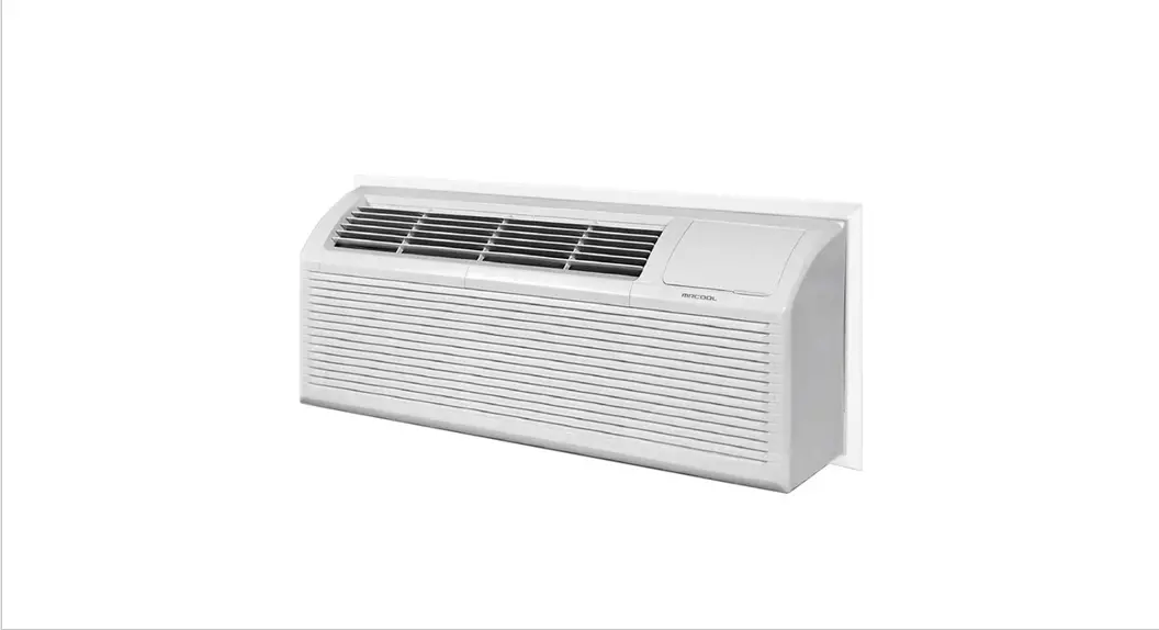
Packaged Terminal
Air Conditioner/Heat Pump
PTAC**5 & PTHP**5
Safety Precautions
Read This Manual Before Using Incorrect usage may cause serious damage or injury.
The symbols below are used throughout this manual to indicate instructions that should be followed closely or actions that should be avoided to prevent death, injury, and/or property damage. Inside this manual, you will also find helpful hints on how to use and maintain your air conditioner properly.
Performing a little preventative care on your part can save you a great deal of time and expense over the life of the air conditioner. Many of the answers to common problems can be found in the charts contained in the troubleshooting section. If a problem or issue arises, reviewing the troubleshooting section first may make calling a service provider unnecessary.
![]() WARNING
WARNING
This symbol indicates ignoring instructions may cause death or serious injury.![]() CAUTION
CAUTION
This symbol indicates ignoring instructions may cause bodily injury, damage to the unit, or other surrounding property.![]() This symbol indicates that you should NEVER perform the indicated action.
This symbol indicates that you should NEVER perform the indicated action.
 WARNING
- Always ensure the power plug is plugged into the outlet properly. If not, it could cause electric shock or fire due to excess heat generation.
- Always ensure the unit has been effectively grounded. Incorrect grounding could cause electric
- Always install the unit with a circuit breaker and a dedicated power circuit. Incorrect installation may cause fire or electric shock.
- If the unit begins to emit strange sounds, smells, or smoke, unplug it immediately. If not, it could cause fire and/or electric shock.
- Always keep firearms away from the unit, as these could cause a fire.
- Always ventilate the room before operating the air conditioner should there be a gas leak from another appliance. Failure to do this could cause an explosion, fire, and/or burns.
![]() DO NOT operate or stop the unit by inserting or removing the power cord plug from the outlet. This could cause electric shock and/or fire due to heat generation.
DO NOT operate or stop the unit by inserting or removing the power cord plug from the outlet. This could cause electric shock and/or fire due to heat generation.![]() DO NOT modify the length of the power cord, or share the outlet with other appliances. This could cause electric shock and/or fire due to heat generation.
DO NOT modify the length of the power cord, or share the outlet with other appliances. This could cause electric shock and/or fire due to heat generation.![]() DO NOT operate this unit with wet hands or in a damp environment. This could cause electric shock.
DO NOT operate this unit with wet hands or in a damp environment. This could cause electric shock.![]() DO NOT allow water to come into contact with the electrical components of the unit. It could cause the failure of the machine and/or electric shock.
DO NOT allow water to come into contact with the electrical components of the unit. It could cause the failure of the machine and/or electric shock.![]() DO NOT use the socket if it is damaged or loose. It could cause fire and/or electric shock.
DO NOT use the socket if it is damaged or loose. It could cause fire and/or electric shock.![]() DO NOT open the unit while it is operating. It could cause electric shock.
DO NOT open the unit while it is operating. It could cause electric shock.![]() DO NOT disassemble or modify the unit. It could cause electric shock.
DO NOT disassemble or modify the unit. It could cause electric shock.![]() DO NOT direct airflow from the unit directly at occupants in the room. This could be hazardous to their health.
DO NOT direct airflow from the unit directly at occupants in the room. This could be hazardous to their health.![]() DO NOT use the power cord close to any heating appliances. It could cause fire and/or electric shock.
DO NOT use the power cord close to any heating appliances. It could cause fire and/or electric shock.![]() DO NOT use the power cord near flammable gas or combustibles, such as gasoline, benzene, thinner, etc. It could cause an explosion and/or fire.
DO NOT use the power cord near flammable gas or combustibles, such as gasoline, benzene, thinner, etc. It could cause an explosion and/or fire.
FOR YOUR SAFETY
![]() DO NOT store or use gasoline, or any other materials or liquids which may contain flammable vapors in the vicinity of this appliance or any other.
DO NOT store or use gasoline, or any other materials or liquids which may contain flammable vapors in the vicinity of this appliance or any other.![]() DO NOT use an extension cord or an adapter plug, as this could cause a fire hazard and/or electric shock.
DO NOT use an extension cord or an adapter plug, as this could cause a fire hazard and/or electric shock.![]() DO NOT remove any of the prongs from the power cord.
DO NOT remove any of the prongs from the power cord.
ELECTRICAL INFORMATION
- Ensure the electrical service is adequate for the model you have chosen. This information can be found on the serial plate located on the side of the cabinet and behind the grille.
- Ensure the air conditioner is properly grounded. Proper grounding is necessary in order to minimize and avoid electrical shock and/or fire hazards. The power cord of this unit is equipped with a three-pronged grounding plug to protect against electrical shock hazards.
- The wall receptacle used for this unit must also be properly grounded. If the wall receptacle intended to be used is not adequately grounded, or protected by a time-delay fuse or circuit breaker, have a qualified electrician install one.
- Ensure the receptacle is still accessible after the unit is installed.
- The appliance should be installed in accordance with national and local wiring regulations.
 DO NOT run the air conditioner without the side protective cover in place. Otherwise, it could result in mechanical damage within the unit. DO NOT use an extension cord or an adapter plug.
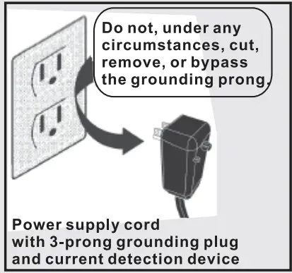
NOTE: The power supply cord used on this air conditioner contains a current detection device that is designed to reduce the risk of fire. Please refer to the Operation of Current Device later in this section of the manual for further details. In the event that the power supply cord becomes damaged, it cannot be repaired. It must be replaced with a cord from the product manufacturer. The illustration below represents different types of power cords (dependent on model).
| Power Cord | 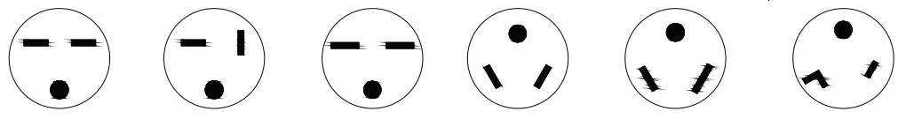 | |||||
| Power Supply | 230V 15A | 230V 20A | 230V 30A | 265V 15A | 265V 20A | 265V 30A |
CAUTION
- This appliance is not intended for use by individuals, and children under the age of 8 years old, with reduced physical, sensory, or mental capabilities. It is also not intended for use by individuals with a lack of experience or knowledge unless they have been given supervision or instruction concerning the use of the appliance by a person responsible for their safety. Children should be supervised at all times to ensure that they do not play with the appliance. Cleaning and user maintenance should not be performed by children.
- If the power cord is damaged, it must be replaced by the manufacturer, its service agent, or a similarly qualified individual in order to avoid a hazard.
- The appliance should be installed in accordance with national wiring regulations.
- The appliance equipped with an electric heater should have at least 3.3 ft (1 m) of distance from combustible materials.
- Contact an authorized service technician to perform repairs or maintenance of this unit.
- Contact an authorized installer for the installation of this unit.
- Should there be any differences between the User’s Manual and Remote Controller illustration regarding function description, the User’s Manual should take precedence.
- If the air conditioner is knocked over during use, turn off the unit, and unplug it from the main power supply immediately. Then, visually inspect the unit to ensure there is no damage. If you suspect the unit has been damaged, contact a qualified technician or customer service for
- Turn off power to the machine during a thunderstorm to avoid damage to the unit from lightning.
- To reduce the risk of fire or electric shock, do not use this fan with any solid-state speed control
- Ensure the room the unit is operating in is well ventilated if used in a room with a stove. If not, it may cause an oxygen shortage.
- Route power cord away from any traffic areas to ensure it will not be tripped over.
- Always hold the plug by the head when unplugging it from an outlet
- Always turn off the main power switch when not using the unit for an extended period of time. If not, it could cause the failure of the product or fire.
- Always ensure that the mounting bracket is not damaged due to prolonged exposure. If the
- bracket is damaged, it could cause it to weaken or fail which could result in the unit falling.
- Always insert the air filters securely. They should be cleaned once every two weeks.
- Use caution when unpacking and installing the unit. It may have sharp edges which could cause
- The evaporator should be cleaned every three months by a qualified professional. If this is not done, it could cause the failure of the electric heating function.
- If water enters the unit, turn the unit off at the power outlet and switch off the circuit breaker. Isolate the unit by unplugging the power cord from the outlet and then contact a qualified service
![]() DO NOT operate the unit without filters. This could cause unit failure.
DO NOT operate the unit without filters. This could cause unit failure.![]() DO NOT operate the unit in a room where it could be exposed to excessive amounts of water such as a bathroom or laundry room.
DO NOT operate the unit in a room where it could be exposed to excessive amounts of water such as a bathroom or laundry room.![]() DO NOT run the power cord under carpeting, throw rugs, runners, or similar items.
DO NOT run the power cord under carpeting, throw rugs, runners, or similar items.![]() DO NOT run the power cord under furniture or appliances.
DO NOT run the power cord under furniture or appliances.![]() DO NOT place heavy objects on the power cord and ensure it is not compressed. This could cause a fire and/or electric shock.
DO NOT place heavy objects on the power cord and ensure it is not compressed. This could cause a fire and/or electric shock.![]() DO NOT touch the metal parts of the unit when removing the air filter as this could cause injury.
DO NOT touch the metal parts of the unit when removing the air filter as this could cause injury.![]() DO NOT clean the unit with water. Water can enter the unit and not only cause electric shock but also degrade the insulation.
DO NOT clean the unit with water. Water can enter the unit and not only cause electric shock but also degrade the insulation.![]() DO NOT attempt to clean the unit while the power is on, as it could cause fire and/or electric shock. When the unit is to be cleaned, turn the power off and turn off the circuit breaker.
DO NOT attempt to clean the unit while the power is on, as it could cause fire and/or electric shock. When the unit is to be cleaned, turn the power off and turn off the circuit breaker.![]() DO NOT allow pets or house plants to be exposed to the direct airflow from the unit, as this could cause injury to them.
DO NOT allow pets or house plants to be exposed to the direct airflow from the unit, as this could cause injury to them.![]() DO NOT use this air conditioner for special purposes such as to preserve precision devices, food, plants, or art. It could cause deterioration of the quality of these items.
DO NOT use this air conditioner for special purposes such as to preserve precision devices, food, plants, or art. It could cause deterioration of the quality of these items.![]() DO NOT operate this unit during a storm or hurricane. Stop operation and close any windows. Operating this air conditioner during a storm with the windows open can result in saturation of the indoor rooms and furnishings with water.
DO NOT operate this unit during a storm or hurricane. Stop operation and close any windows. Operating this air conditioner during a storm with the windows open can result in saturation of the indoor rooms and furnishings with water.![]() DO NOT place obstacles around the air inlets or inside of the air outlet. It could cause the failure of the appliance or cause an accident.
DO NOT place obstacles around the air inlets or inside of the air outlet. It could cause the failure of the appliance or cause an accident.![]() DO NOT use strong detergent such as wax or thinner as these could deteriorate the appearance of the unit by changing the color or scratching the surface. Only use a soft cloth to wipe the unit clean.
DO NOT use strong detergent such as wax or thinner as these could deteriorate the appearance of the unit by changing the color or scratching the surface. Only use a soft cloth to wipe the unit clean.![]() DO NOT drink water drained from the air conditioner, as it contains contaminants that could make you sick.
DO NOT drink water drained from the air conditioner, as it contains contaminants that could make you sick.
OPERATION OF CURRENT DETECTION DEVICE (optional)
The power supply cord of this device contains a current detection device that is designed to sense damage to the power cord. To test this function, please follow these steps: 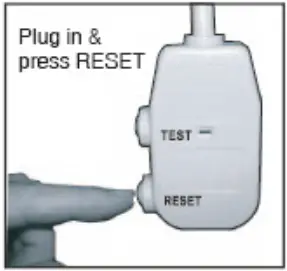
(NOTE: Some plugs have buttons on the top.
- Plugin the air conditioner
- The head of the power cord will have TWO buttons, TEST, and RESET. Press the TEST button and you will hear a click as the RESET button pops out.
- Press the RESET button and you will hear a click as the button engages back into the head of the plug.
- The power cord is now supplying electricity to the unit.
NOTE: On some products, this will also be indicated by a light on the plug head.
- Always ensure the reset button is pushed in and engaged for correct operation.
- The power supply must be replaced if it fails to reset when either the TEST button is pushed, or it cannot be reset. A new power supply can be obtained from the product manufacturer.
- If the power cord is damaged, it cannot be repaired. It must be replaced by one obtained from the product manufacturer.
- When 265V units are installed, the power supply must be a part of permanent wiring. Permanent wiring may be done through the accessory sub-base. An exposed cord connection on 265V units is not permitted.
Air Conditioner Features
This unit has many features that the service technician must be familiar with in order to properly service the unit.
Compressor Restart Delay
This feature extends the overall life of the compressor by preventing short-cycling of the air conditioner. When the compressor restarts, the unit is designed to give a minimum of 3 minutes in order to allow enough time for refrigerant pressures to equalize for optimized cycling.
Memory
The unit has a memory function to restore settings after a loss of power. Should there be a power outage or a loss of power, the system is designed to remember all of the previous control settings (mode, fan speed, on/off, and the configuration). Once power is restored, the unit will restart with the settings and in the mode that was selected at the time the power was lost.
Automatic Evaporator Freeze Protection
When the temperature of the evaporator reaches a level that is too low, this function engages automatically to prevent the evaporator from freezing. It accomplishes this by turning the compressor off and turning the fan on. Once the evaporator temperature reaches a safe level, this function will automatically turn off.
Automatic Quick Warm-up (for heat pump models only)
This function turns on when the room temperature falls to 8°F (4.5°C) below the set temperature of the unit. During this process, the reverse cycle heat is shut off and the electric heat strip is turned on for one cycle until heating is satisfied.
LED Indicators and Buttons
The touchpad of the unit has buttons to control the MODE, FAN, and directional arrows to increase and decrease the set-point of the temperature. The unit is also equipped with LED indicators that correspond to the MODE, FAN SPEED, and TEMPERATURE SET-POINT to indicate the status of the unit. The unit has LEDs to indicate which speed the fan is set to, HIGH, MEDIUM, and LOW. There are also LED indicators for FAN, COOL, and HEAT to indicate which of the operating modes is currently selected. There is also an LED indicator for the POWER setting. If the unit is ON the LED will illuminate green. If the unit is OFF, the LED will also be off. NOTE: HEAT Mode is for Cooling & Heating models only.
High-Temperature Protection while operating in Heat Mode
The compressor and/or electric heater will automatically shut off if the system senses the temperature of the indoor airflow from the unit is too high. It will also shut-off if the system senses there is an error with the indoor temperature sensor
Temperature Unit Display Configuration (°F or °C)
The display of the unit can be set to display the temperature in either Fahrenheit or Celsius.
Control Panel Operation
Control Panel Keypad
The control panel keypad will look similar to the illustration in Fig 2.1. This will be used to control most, if not all, of the functions of the unit.
NOTE: some models may be equipped with a REMOTE SIGNAL RECEPTOR. If this is the case, the unit can be controlled with the control panel keypad or by the remote control.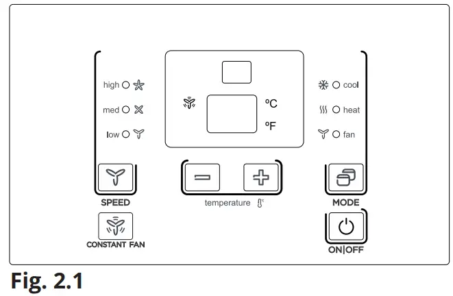
Power
Press the POWER button to turn the unit on or off.
Mode
Push this button to cycle through and select the desired mode: COOL, HEAT, or FAN. The indicator light beside the mode selected will illuminate.
- COOL: In this mode, cooling will begin automatically when the room temperature is 4°F (2°C) below the set temperature. The compressor will run for at least 5 minutes in this mode before stopping.
- HEAT: In this mode, the temperature can be set to a maximum of 84°F (29°C). For heat pump models, the unit will alternate between reverse cycle heat mode and electric heater mode depending upon the difference between the temperature the unit is set to and the room temperature. The fan motor will cycle with the compressor.
- FAN: The fan operates without heating or cooling activated (Fan-Only mode). NOTE: If the unit features DIP SWITCHES, these can be used to set the temperature range. Please see the DIP Switch Configurations section for further information.
NOTE
The reverse cycle and electric heater cannot be run at the same time. In the scenarios listed below, it is normal that the unit does not operate in reverse cycle mode:
- When the outdoor temperature is lower than 40°F (4°C) or the room temperature falls to 8°F (4.5°C) below the set temperature of the unit, reverse cycle mode will not
- There is a 3-minute minimum compressor run time at any setting to prevent it from short cycling. The indoor fan motor will start before the compressor and stop after the compressor has cycled off.
- Pushing the “S1” on the DIP SWITCHES to the UP (ON) position will prevent the unit from operating in reverse cycle mode.
- When the frost builds up on the evaporator coils, the unit will automatically defrost and the compressor will cycle off.
Up/Down Buttons (+/-)
Push the UP or DOWN buttons to increase or decrease the temperature setting of the unit in cooling or heating mode. The temperature can be adjusted in increments of 1°F (1°C) with each press of the button. The set temperature will show on the unit display. NOTE: Pressing and holding the + and – buttons together will alternate the temperature display between
°F and °C.
SPEED (Fan Speed)
Every push of this button will change the fan speed setting to either HIGH, MEDIUM, and LOW.
Constant Fan Mode
In cooling mode, press the button to turn the constant fan setting on or off. When this function is turned on, the constant fan light will illuminate. This indicates the fan is continuously running for cooling. When this function is turned off, the constant fan light will no longer be illuminated, and the fan will go back to cycling with the compressor.
Displays
The display panel on the unit will show the set temperature in either °F or °C. While in Fan-Only Mode, the display will show the room temperature.
Control Codes (on some models):
- LC – Keypad on the control panel is not available. The unit can only be set using the wired controller.
- FC – Keypads on the control panel and wire controller are not available. The unit can only be set by using the Front Desk Control only.
Error Codes:
AS – Room temperature sensor error;
ES – Evaporator temperature sensor error;
CS – Condenser temperature sensor error;
OS – Outside temperature sensor error;
HS – Exhaust temperature sensor error;
LE – Wire controller error;
NOTE: When an error occurs, unplug the unit and plug it back in. If the error repeats, call a service professional.
Other Codes:
LO – Room temperature is lower than 32°F (0°C);
HI – Room temperature is higher than 99°F (37°C);
FP – Low-temperature protection;
Unit Operating Temperature Ranges
| Cooling Operation | Outdoor Temperature* | 64°F – 109°F (18°C – 43°C) |
| Indoor Temperature | 62°F – 90°F (17°C – 32°C) | |
| Heating Operation | Outdoor Temperature | 23°F – 76°F (-5°C – 24°C) |
| Indoor Temperature | 32°F – 80°F (0°C – 27°C) |
* Outdoor temperature range for special tropical models 64°F-125°F (18°C-52°C).
NOTE: This air conditioner is designed to be operated in the temperature ranges listed in the table above. If the unit is operated outside of these temperature ranges, performance could be reduced.
Accessory
NOTE: When the unit displays LC, the keypad on the control panel may not available. The unit can be set by using the wired controller only. You can install the controller on the control panel.
NOTE: For some models, there may be a 3-second delay after pressing any button before the selected operation will occur.
NOTE: When there are wide differences between the User’s Manual and Remote Controller Illustration when describing the functions, what is written in the User’s Manual will take precedence.
NOTE: All illustrations contained in this manual are for demonstration and explanation purposes only. Your actual unit may vary in shape, size, and general appearance.
DIP Switch Configuration (Optional)
Remove the Front Panel
- The DIP switch controls are located behind the front panel through an opening that is beneath the control panel. To gain access to this, the front panel will need to be removed.
Please refer to Fig. 3.1 for the proper procedure of removing the front panel. - The DIP switches are accessible without opening the control box. Please refer to Fig. 3.2.
- Always make sure the unit is powered off before making adjustments to the DIP switches.
DIP Switches Configuration
Refer to Table 1 and Fig. 3.3 for the DIP Switches configurations and the functions of each DIP switch.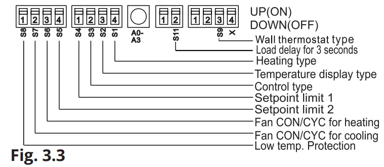
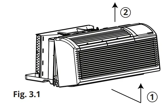
- Pull the front panel out from the bottom to release it from the tabs.
- Then lift the panel upward.
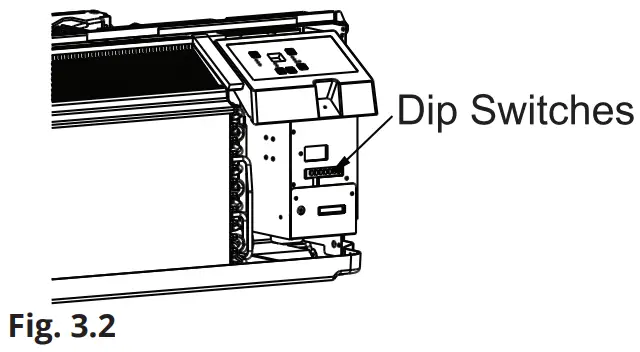
Table 1 – DIP Switch Configurations
| No. | Up Position (ON) | Down Position (OFF) | Remarks |
| S1 | Electric Heat Only | Electric Heat and Heat Pump | For the Heat Pump unit only |
| S2 | Temperature Display in °F | Temperature Display in °C | |
| S3 | Wall Thermostat Enabled | Control Panel Enabled | |
| S4 & S5 | Up & Up: 61°F – 86°F (16°C – 30°C) Up & Down: 65°F – 78°F (18°C – 26°C) Down & Up: 63°F – 80°F (17°C – 27°C) Down & Down: 68°F – 75°F (20°C – 24°C) | The setting of two switches (S4 & S5) combine to select the temperature range of unit | |
| S6 | Continuous Fan Operation for Heating | Fan Cycle for Heating | |
| S7 | Continuous Fan Operation for Cooling | Fan Cycle for Cooling | |
| S8 | Low Temp. Protection Enabled | Low Temp. Protection Disabled | Optional |
| S9 (with S3 Up) | To use some types of Wall Thermostat | To use PTAC or another wall thermostat | Consult with retailer or manufacturer for details |
| S9 (with S3 Down) | Use Control Panel Only | To use a Control Panel or some type of wall thermostat | Use a Control Panel or type of wall thermostat, the other one must be turned off |
| Sw11 | Load Delay for 3 seconds | Normal | Optional |
DIP Switch Configuration
NOTE: On Heating Mode, the temperature cannot be set higher than 84°F (29°C).
Enable Wall Thermostat
A wired wall thermostat can be connected to the unit. If this is the case, the corresponding dip switch (Refer to Table 1) must be switched to the position to enable the Wall Thermostat before it can begin controlling the unit.
Low-Temperature Protection (optional)
If the unit the room temperature is below 32°F (0°C), the fan motor and electric heat strip will activate and warm the room to a temperature of 40°F (4.4°C). Shortly after this temperature has been reached, the fan will stop.
Electric Heat Only (for heat pump units only)
This setting is typically used for emergency heating.
Heat and Cool Fan CON/CYC DIP-switches
These switches allow the fan to either operate continuously or in cycle mode while the unit is operating in heating or cooling mode.
- CON (Continuous)
Enables the fan to run continuously allowing air to circulate even after the set temperature has been reached. This switch helps to maintain the room temperature closer to the set temperature on the unit. - CYC (Cycle)
This setting enables the fan to cycle on and off with the compressor or electric heater. The fan will stop a short time after the set temperature has been reached.
Temperature Set-Point Limits
Enables a restricted range of temperature control.
DIP Switch Configuration by Panel Control (Optional)
- DIP Switch Configuration by Panel Control Turn off the unit.
- Press the up (+) and down (-) buttons together for 3 seconds to activate the DIP switch configurations on the control panel.
Refer to Fig 4.1. - Refer to Table 1 below for the control panel DIP switch configurations and functions. NOTE: Press the up (+) and down (-) buttons together for 3 seconds again (or do not complete any further operations for 30 seconds) to exit the DIP switch configuration and the unit will save the last settings entered.
- Display function settings, with 2 digits in the LED display window. The first digit will represent the high (left) for DIP switches. The second digit will represent the low (right) for functions. Please refer to Fig. 4.1 and the table below. Press the up (+) button to set the dip switches, press the down (-) button to set the functions.
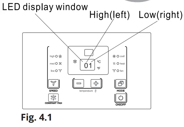
Table 1 – DIP Switch Configurations by Control Panel
No. | High (left) | Low (right) | Remarks | ||
| / | 0 | 1 – by Control Panel | 0 – by DIP switches | ||
| S1 | 1 | 1 – Electric Heat Only | 0 – Electric Heat and Heat Pump | For Heat Pump units only | |
| S2 | 2 | 1 – Temperature Display in °F | 0 – Temperature Display in °C | ||
| S3 & S9 | 3 | 3- Use Control Panel or Some Types of Wall Thermostat; 2- Use Some Types of Wall Thermostat; 1- Use PTAC or Other Wall Thermostat; 0- Enable Control Panel | Consult with the retailer or manufacturer for details | ||
| S4 & S5 | 4 | 4 – 62°F – 86°F (17°C – 30°C) 3 – 61°F – 86°F (16°C – 30°C) 2 – 65°F – 78°F (18°C – 26°C) 1 – 63°F – 80°F (17°C – 27°C) 0 – 68°F – 75°F (20°C – 24°C) | |||
| S6 | 6 | 1 – Continuous Fan Operation for Heating | 0 – Fan Cycle for Heating | Not available for use PTAC another wall thermostat | |
| S7 | 7 | 1 – Continuous Fan Operation for Cooling | 0 – Fan Cycle for Cooling | ||
| S8 | 8 | 1 – Low- temperature Protection Enabled | 0 – Low Temp. Protection Disabled | Optional | |
| SW7 | A | 1 – Front Desk Control Disabled | 0 – Front Desk Control Enabled | Optional | |
| Sw11 | B | 1 – Load Delay for 3 seconds | 0 – Normal | Optional | |
NOTES:
- The LED display window will show “00” when you first enter the setting mode, only when you set “01” can you move onto the next setting.
- To activate the front desk control function, you need to flip the SW7 dip switch in the down (off) position, and then set the panel control to “A0.”
- After all the settings have been set, press the up (+) and down (-) buttons together for 3 seconds to exit the operation interface and turn off the power. Once power is turned back on, the settings will be activated.
Wall Thermostat Terminal (Optional)
![]() IMPORTANT
IMPORTANT
Only trained, qualified personnel should access the electrical panel on the unit and install electrical accessories. Please contact your local electrical contractor, dealer, or distributor for assistance.
Thermostat Wire Routing
Thermostat wire is field supplied. Recommended wire gauge is 18 to 20 gauge solid thermostat wire.
NOTE: It is recommended that extra wires are run to the unit in case any are damaged during installation. The thermostat wire should always be routed around or under, NEVER through the wall sleeve. The wire should then be routed behind the front panel to the easily accessible terminal connector. Please refer to Fig. 5.1. 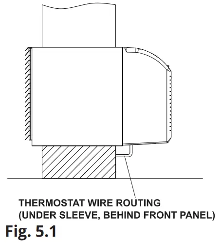
NOTE: Refer to the thermostat installation instructions for further details on installing the wall thermostat.
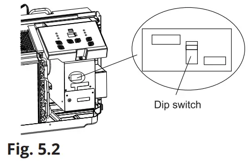
Installation instructions of some types of wall thermostats (it may be necessary to consult with the retailer or manufacturer for details.)
- Pull the DIP switch to the Down (Off) position as shown in Fig. 5.2.

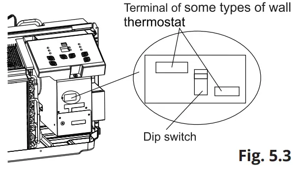
- Insert the wire connector of the wall thermostat into the corresponding terminal as shown below. The correct term to use is dependent upon the shape of the wall
thermostat connector. Refer to Fig. 5.3.
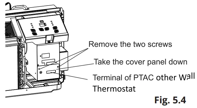
Installation Instructions of PTAC other Wall Thermostat
- Remove the two screws and take the cover panel down, as shown in Fig. 5.4 below. Refer to Fig. 5.5 on the next page for the terminal diagrams.
Wall Thermostat Terminal (Optional)
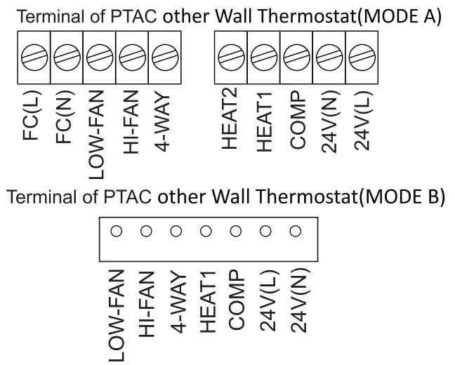
| TERMINAL | DESIGNATION |
| FC(L) | Front desk control terminal L |
| FC(N) | Front desk control terminal N |
| LOW-FAN | Low fan speed |
| HI-FAN | High fan speed |
| 4-WAY | 4-way valve; Reverse cycle (Energized in Heat) For heat pump models |
| HEAT2 | Electrical heater 2 |
| HEAT1 | Electrical heater 1 |
| COMP | Compressor |
| 24V(N) | 24VAC terminal N(Neutral), Common |
| 24V(L) | 24VAC terminal L |
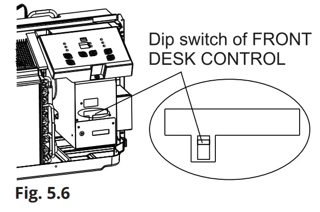
Front Desk Control
The controller can handle a switch signal from FC(L) and FC(N) input, referred to as front desk control. The input must be 24VAC. If the system does not receive a 24VAC signal, it will turn off. Otherwise, the unit will run under normal control.
- The DIP switch can control the FRONT DESK CONTROL feature. If the DIP switch is in the DOWN position, the unit will be turned off, otherwise, the unit will run under normal control. Refer to Fig. 5.6 below.
CAUTION
Unit damage or improper operation could occur if the points listed in this caution are not followed.
Improper wiring could damage unit electronics. Common busing is not permitted. Damage or erratic operation may result.
Unit damage or improper operation could occur if the points listed in this caution are not followed. Improper wiring could damage unit electronics. Common busing is not permitted. Damage or erratic operation may result.
- Only use 4-way terminal for heat pump connection only.
- It is recommended to set the compressor protection time for more than 3 minutes on the wall If it is set for less than 3 minutes, the compressor will still delay restart for 3 minutes.
- The Wall thermostat must have a 4-way valve for heating change-over.
- For thermostats that have only one fan speed output (on or auto), the fan speed is determined by how the terminal connector is wired. If low fan speed is desired, wire the G output from the thermostat to (LOW-FAN) on the unit’s terminal block. If high fan speed is desired, wire the G output from the thermostat to (HI-FAN) on the unit’s terminal block.
- The temperature range of the wall thermostat must correspond with the DIP switch setting of the
- The wall thermostat must be of a type that is compatible with the unit type: heat pump or no heat
- If the wall thermostat has only one electrical heater output, connect the two terminals of HEAT 1
and HEAT 2. The unit can operate two electrical heaters (if the unit has two electrical heaters).DO NOT remove the control panel.
Installation
- Installation Preparation and Overview If using an existing sleeve, you should measure the wall sleeve dimensions.
- Install the new air conditioner according to these installation instructions to achieve the best performance.
- All wall sleeves used to mount the new air conditioner must be in good structural condition. It must also have a rear grille that securely attaches to
the sleeve, or the flange of the sleeve, in order to secure the new air conditioner. - To avoid vibration and noise, ensure the unit is installed securely and firmly.
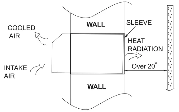
- When installing the sleeve, ensure there are no objects or obstructions within 20 in (508 mm) of the rear of the unit that could interfere with heat radiation and exhaust airflow.
Preparation of Sleeve Assembly
Refer to the installation instructions of the sleeve assembly for further details.
Preparation or Rear Grille Assembly (optional)
Refer to the installation instructions of the rear grille assembly for further details.
Unit Installation
- Carefully remove shipping tape from the front panel.
Please refer to Fig. 6.1. - Then, remove the front panel. Please refer to Fig. 6.2.
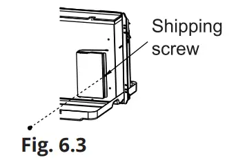
- Remove the shipping screw from the vent door.
Please refer to Fig. 6.3.
![]() CAUTION
CAUTION
- Use caution when picking up or moving the unit as there are sharp edges that can cause injury.
- Use two people when lifting the air conditioner as it is heavy.
Dimensions of Air Conditioner Unit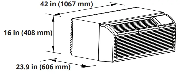
Dimensions of Assembly Sleeve (optional)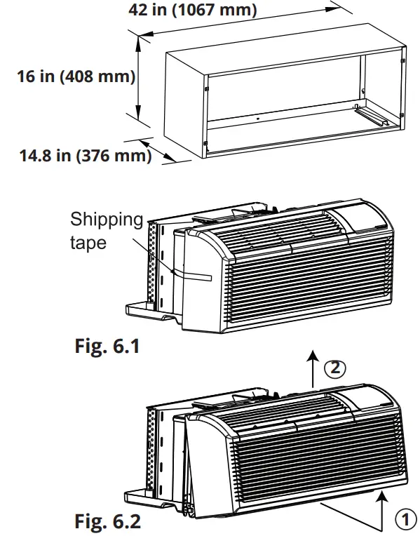
Steps To Remove Front Panel
- Pull the front panel out from the bottom to release it from the tabs.
- Then lift the panel upward.
Unit Installation
Unit Installation (Continued)
5. Rotate the vent control lever to open or close the vent door.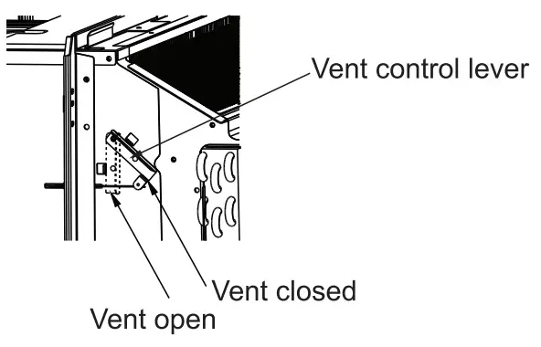
NOTE: When the vent control lever is set to CLOSE, only the air inside the room is circulated and filtered. When it is set to OPEN, some outdoor air will be drawn into the room. This will reduce the heating and cooling efficiency.
6. Lift the unit until it is level and slide it into the wall sleeve until it is firmly against the front of the wall sleeve. Then, secure it with 4 screws and washers (supplied with the sleeve assembly) through the unit flange holes. Refer to Fig. 6.4 and Fig. 6.5. 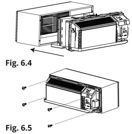
7. Using the image below as a guide, reinstall the front panel by first placing the tabs of the panel over the top rail of the unit. Second, push inward at the bottom of the panel until it snaps into place.
Please refer to Fig. 6.6.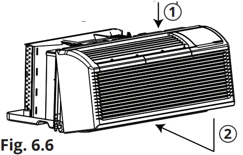
![]() CAUTION
CAUTION ![]() DO NOT put obstacles around the air-inlet or inside of the air outlet of the unit (such as a window curtain, etc.).
DO NOT put obstacles around the air-inlet or inside of the air outlet of the unit (such as a window curtain, etc.).
Always insert the filter securely.
Be sure to clean the filter once every two weeks as required.
Care and Cleaning
Front Panel and Case
To clean the front panel and case, first turn off the power to the unit and disconnect the power supply. Only use water and a mild detergent to clean the unit. DO NOT use bleach or abrasives. Some commercial cleaners could damage the plastic parts of the unit.
Outdoor Coil
The coil located on the outdoor side of the unit should be checked regularly. The unit will need to be removed in order to inspect the dirt build-up that will occur on the inside of the coil. If the coil is clogged with dirt and soil, it should be professionally cleaned. The inside and outside of the outdoor coils should be cleaned on a regular basis. NOTE: Never use a high-pressure spray on the coil, as it could cause damage.
Air FIlters
Ensure the unit is turned off before attempting to clean the filters. Cleaning the air filters is the most important maintenance you can do to maintain unit efficiency. Clogged air filters will reduce cooling, heating, and airflow. Clean the filters once every two weeks. Cleaning the filters regularly will offer the following benefits:
- Decrease the cost of operation
- Save energy
- Prevent indoor coil from clogging
- Reduce the risk of premature component failure
To clean the air filters follow the steps below and refer to Fig. 7.1 and Fig. 7.2:
- Remove the two air filters, by pulling up on the top of each filter located on the front panel of the
- Vacuum any heavy soil that has accumulated on the filters.
- Run water through the filters.
- Dry the filters thoroughly before
- To replace the air filters, insert each filter back into their respective slots on the front panel and push down until it slides back into
Removing the Air Filter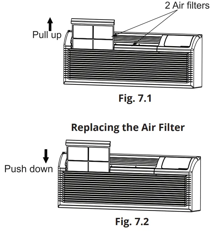
![]() CAUTION
CAUTION
Failure to read and follow these cautions could result in equipment damage or improper operation.
- Any airflow restrictions could cause damage to the unit.
DO NOT operate the unit without the filters installed. If a filter becomes torn or damaged it should be replaced immediately. Operating the unit without filters installed, or with a damaged filter, will allow dirt and dust to reach the indoor coil and reduce cooling, heating, airflow, and efficiency.
Care and Cleaning
Vent Door Filter
Ensure that the unit is off before attempting to clean the vent door filter. If the vent door is open, access requires the removal of the unit from the wall sleeve. Clean the filter twice a year, or as required.
To clean the filter follow the steps below and refer to Fig. 6.3 (in section 6) and Fig. 7.3: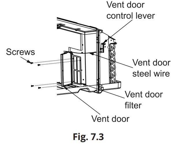
- Ensure the shipping screw has been removed from the vent door. Refer to Fig. 6.3.
- Rotate the vent control lever to open the vent door.
- Remove the four screws from the vent door filter.
- First, pull out the vent door steel wire from the hole of the vent door. Then, take off the vent door and filter.
- Clean the filter and dry it thoroughly before reinstalling it.
- Reinstall the vent door, filter, and four screws.
- Then, reinstall the vent door steel wire into the hole of the vent door.
Troubleshooting
| Possible Cause | Solutions |
| U.NIT DOES NOT START . The unit may have become unplugged. . The fuse may have blown. . The circuit breaker may have been tripped. . The unit may be turned off. The unit may be in a protection mode. | . Check that the plug is plugged securely into the outlet. NOTE: The plug has a test /reset button on it. Ensure. that the plug has not been tripped. . Replace the fuse (see note 1 below). . Reset circuit breaker (see note 1 below). Turn the unit on (bottom right button on the keypad). |
| UNIT IS NOT COOLING OR HEATING THE R.OOM . Unit air discharge section is blocked. The temperature setting is not high or low enough. NOTE: Temperature Set-point limits may not allow the unit to heat or cool the room to the desired temperature. Refer to the DIP switch configuration. section of the manual. . Unit air filters are dirty or clogged. The room is excessively hot or cold when the unit. is started. . The vent door has been left open. . The unit could be in protection mode. The compressor is in time delay. | Ensure that curtains, blinds, or furniture are not. restricting or blocking unit airflow. . Reset the temperature to a higher or lower setting. |
| DISPLAY IS SHOWING STRANGE NUMBERS OR CHARACTERS ON IT | . The unit could be in protection mode. The unit may be set for °C, instead of °F. |
| UNIT MAKING NOISES | Clicking, gurgling, and whooshing noises are normal during the operation of the unit. |
| WATER DRIPPING FROM THE UNIT OUTSIDE | If a drain kit has not been installed, condensation runoff during extremely hot and humid weather is. normal (See note 2 below). If a drain kit has been installed and is connected to a drain system, check the gaskets and fittings around the drain for leaks and clogs. |
| W.ATER DRIPPING INSIDE The Wall sleeve has not been installed level. | Wall sleeve must be installed level for proper drainage of condensation. Check that the sleeve has been installed level. If it has not been, make any necessary adjustments. |
| Possible Cause | Solutions |
| ICE OR FROST FORMS ON INDOOR C.OIL . Low outdoor temperature. Dirty or clogged filters. | . When the outdoor temperature is approximately 55°F (12.8°C) or below, frost could form on the indoor coil when the unit is operating in COOLING mode. Switch the. unit to FAN operation until the ice or frost melts. Remove and clean filters. |
| C.OMPRESSOR PROTECTION Power may have cycled, so the compressor is in restart protection. | Random Compressor Restart – Whenever the unit is plugged in, or power has been restarted, a random compressor restart will occur. After a power outage, the =. the compressor will restart after approximately 3 minutes. Compressor Protection – To prevent short-cycling of the compressor, there is a random start-up delay of 3 minutes and a minimum compressor run time of 3 minutes. |
| ELECTRIC HEATING FAILURE | Clean the evaporator once every 3 months by a qualified technician or professional. |
![]()
The design and specifications of this product and/or manual are subject to change without prior notice.
Consult with the sales agency or manufacturer for details.
Due to updates and constantly improving performance, the information and instructions within this manual are subject to change without notice. Please visit
www.mrcool.com/documentation to ensure you have the latest version of this manual.
Version Date: 06-25-21
DISCLAIMER: The images and illustrations used in this manual are for demonstration and explanation purposes only. The actual shape and size of the unit and components therein may vary.


