KLIMAIRE PTAC Terminal Heat Pump
Introduction
IMPORTANT NOTE:
Read this manual carefully before installing or operating your new air conditioning unit. Make sure to save this manual for future reference.
For more information please visit www.klimaire.com
Troubleshooting
Error Display
| Codes | Contents |
| AS | Open or short circuit of T1 temperature sensor |
| ES | Open or short circuit of T2 temperature sensor |
| CS | Open or short circuit of T3 temperature sensor |
| oS | Open or short circuit of T4 temperature sensor |
| HS | Open or short circuit of T5 or T6 temperature sensor |
| Lo | Temperature is lower than display range(0℃/32℉) |
| HI | Temperature is higher than display range(37℃/99℉) |
| E4 | Communication malfunction between main control board and display board. |
| LE | Drive-by-wire control failure |
Troubleshooting
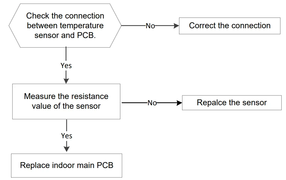
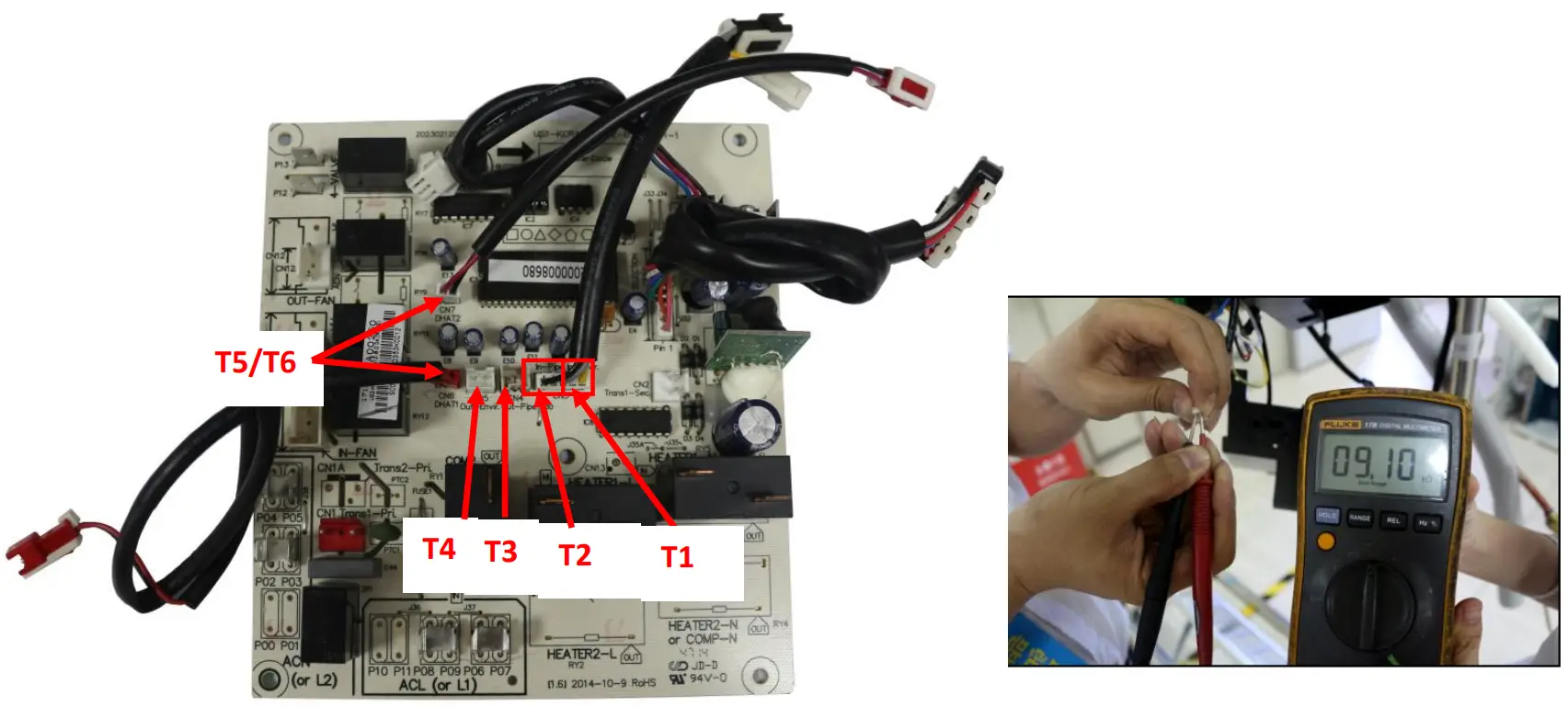
Open circuit or short circuit of temperature sensor diagnosis and solution(AS/E5/CS/oS/HS)
| Error Code | AS/E5/CS/oS/HS |
| Malfunction decision conditions | If the sampling voltage is lower than 0.06V or higher than 4.94V, the LED will display the failure. |
| Supposed causes |
|
Troubleshooting:
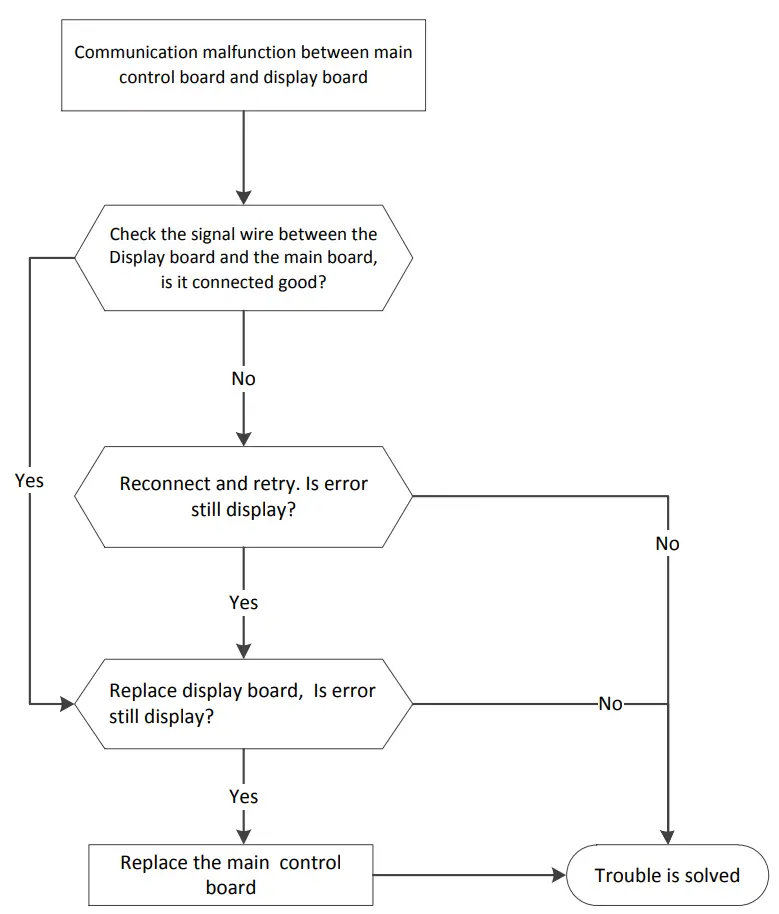
Communication malfunction between main control board and display board. (E4)
| Error Code | E4 |
| Malfunction decision conditions | Main control board does not receive feedback from display board during 120 seconds. |
| Supposed causes |
|
Troubleshooting:
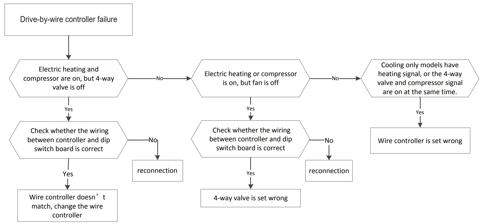
Drive-by-wire controller failure. (LE)
| Error Code | LE |
| Malfunction decision conditions |
|
| Supposed causes |
|
Troubleshooting:
DIP SWITCH TERMINAL | DESIGNATION | 24V CONTROLLER |
FC(L) | Front desk control terminal L | |
| FC(N) | Front desk control terminal N | |
LOW-FAN | Low fan speed | GL |
| HI-FAN | High fan speed | GH |
4-WAY | 4-way valve(for heat pump model) | B |
| HEAT2 | Electrical heater 2 | W |
HEAT1 | Electrical heater 1 | (W) |
| COMP | Compressor | Y |
24V(N) | 24VAC terminal N COM | C |
| 24V(L) | 24VAC terminal L | R |
| POSSIBLE CAUSES | SOLUTONS |
| UNIT DOES NOT START Unit may have become unplugged Fuse may have blown | Check that plug is plugged securely in wall receptacle. Note: Plug has a test/reset button on it. Make sure that the plug has not tripped. Replace the fuse. See Note 1. Reset circuit breaker. See Note 1. Turn unit on (bottom right button on keypad). |
| UNIT NOT COOLING/HEATING ROOM Unit air discharge section is blocked Temperature setting is not high or low enough Note: Setpoint limits may not allow the unit to heat or cool the room to the temperature desired. Check section on dipswitch settings. Unit air filters are dirty. Room is excessively hot or cold when unit is started. Vent door left open. Unit may be in a protection mode. Compressor is in time delay. | Make sure that curtains, blinds or furniture are not restricting or blocking unit airflow. Reset to a lower or higher temperature setting. Remove and clean filters. Allow sufficient amount of time for unit to heat or cool the room. Start heating or cooling early before outdoor temperature, cooking heat or gatherings of people make room uncomfortable. Close vent door. Check dipswitch settings for desired comfort. Wait approximately 3 minutes for compressor to start. |
| DISPLAY HAS STRANGE NUMBERS/ CHARACTERS ON IT | The unit may be in a protection mode. The unit may be set for ℃(instead of ℉). |
| UNIT MAKING NOISES | Clicking, gurgling and whooshing noises are normal during operation of unit. |
| WATER DRIPPING OUTSIDE | If a drain kit has not been installed, condensation runoff during very hot and humid weather is normal. See Note 2.If a drain kit has been installed and is connected to a drain system, check gaskets and fittings around drain for leaks and plugs. |
| WATER DRIPPING INSIDE Wall sleeve is not installed level | Wall sleeve must be installed level for proper drainage of condensation .Check that installation is level and make any necessary adjustments. |
| ICE OR FROST FORMS ON INDOOR COIL Low outdoor temperature Dirty filters | When outdoor temperature is approximately 55℉ or below, frost may form on the indoor coil when unit is in Cooling mode. Switch unit to FAN operation until ice or frost melts. Remove and clean filters. |
| COMPRESSOR PROTECTION Power may have cycled, so compressor is in a restart protection. | Random Compressor restart-Whenever the unit is plugged in, or power has been restarted, a random compressor restart will occur. After a power outage, the compressor will restart after approximately 3 minutes. Compressor Protection-To prevent short cycling of the compressor, there is a random startup delay of 3 minutes and a minimum compressor run time of 3 minutes. |
| ELECTRIC HEATING FAILURE | Clean the evaporator once every three months by professional people. |
NOTES:
- If circuit breaker is tripped or fuse is blown more than once, contact a qualified electrician.
- If unit is installed where condensation drainage could drip in an undesirable location, an accessory drain kit should be installed and connected to drain system.
Temp.℃/℉ | Resistance KΩ | Temp.℃/℉ | Resistance KΩ | Temp.℃/℉ | Resistance KΩ |
-10/14 | 62.2756 | 17/62 | 14.6181 | 44/111 | 4.3874 |
| -9 /15.8 | 58.7079 | 18/64 | 13.918 | 45/113 | 4.2126 |
-8 /17.6 | 56.3694 | 19/66 | 13.2631 | 46/115 | 4.0459 |
| -7 /19.4 | 52.2438 | 20/68 | 12.6431 | 47/117 | 3.8867 |
-6 /21.2 | 49.3161 | 21/70 | 12.0561 | 48/118 | 3.7348 |
| -5 /23 | 46.5725 | 22/72 | 11.5 | 49/120 | 3.5896 |
-4 /24.8 | 44 | 23/73 | 10.9731 | 50/122 | 3.451 |
| -3 / 26.6 | 41.5878 | 24/75 | 10.4736 | 51/124 | 3.3185 |
-2 / 28.4 | 39.8239 | 25/77 | 10 | 52/126 | 3.1918 |
| -1 /30.2 | 37.1988 | 26/79 | 9.5507 | 53/127 | 3.0707 |
0 /32 | 35.2024 | 27/81 | 9.1245 | 54/129 | 2.959 |
| 1 /33.8 | 33.3269 | 28/82 | 8.7198 | 55/131 | 2.8442 |
2 /35.6 | 31.5635 | 29/84 | 8.3357 | 56/133 | 2.7382 |
| 3 /37.4 | 29.9058 | 30/86 | 7.9708 | 57/135 | 2.6368 |
4 /39.2 | 28.3459 | 31/88 | 7.6241 | 58/136 | 2.5397 |
| 5 /41 | 26.8778 | 32/90 | 7.2946 | 59/138 | 2.4468 |
6 /42.8 | 25.4954 | 33/91 | 6.9814 | 60/140 | 2.3577 |
| 7 /44.6 | 24.1932 | 34/93 | 6.6835 | 61/142 | 2.2725 |
8 /46.4 | 22.5662 | 35/95 | 6.4002 | 62/144 | 2.1907 |
| 9 /48.2 | 21.8094 | 36/97 | 6.1306 | 63/145 | 2.1124 |
10 /50 | 20.7184 | 37/99 | 5.8736 | 64/147 | 2.0373 |
| 11 /51.8 | 19.6891 | 38/100 | 5.6296 | 65/149 | 1.9653 |
12 /53.6 | 18.7177 | 39/102 | 5.3969 | 66/151 | 1.8963 |
| 13 /55.4 | 17.8005 | 40/104 | 5.1752 | 67/153 | 1.830 |
14 /57.2 | 16.9341 | 41/106 | 4.9639 | 68/154 | 1.7665 |
| 15 /59 | 16.1156 | 42/108 | 4.7625 | 69/156 | 1.7055 |
16 /60.8 | 15.3418 | 43/109 | 4.5705 | 70/158 | 1.6469 |
Customer Support
The Klimaire logo is a registered Trademark of Klimaire Products inc.
Copyright 2020 Klimaire Products Inc.
2190 NW 89 Place, Doral, FL 33172 – USA
Tel: (305)594-4972
www.klimaire.com
Fax (305} 675-2212
[email protected]