Boreal International 13+ SEER Air Conditioners and Heat Pumps Instruction Manual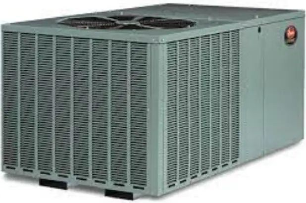
General information
Only qualified persons must install this equipment in accordance with these instructions.
Important: These instructions are intended for the use of qualified individuals specially trained and experienced in the installation of this type of equipment and related system components. Installation and service personnel are required by some states to be licensed.
![]() WARNING
WARNING
Incorrect installation may damage equipment, can create a shock hazard, and voids the warranty.
Contents of kit
The compressor hard start kit consists of a potential (start) relay, screws, capacitor strap, and start capacitor with wiring leads. The kit may contain more hardware than necessary for some models and the wires may be longer than required.
![]() CAUTION
CAUTION
Do not mismatch kits because this may cause damage to the compressor.
Table 1 Corresponding figure for each applicable model
| Figures | Applicable models |
| 1 | AC6B, AC8B, AL6B, AL8B, CZF, CZH |
| 2 | HC6B, HC8B, HL6B, HL8B, YZF, YZH |
| 3 | CCJD, CCJF, LCJD, LCJF, RAC13J, RAC14J, TCJD, TCJF, YCJD, YCJF |
| 4 | CHJD, CHJF, LHJD, LHJF, RHP13J, RHP14J, TCJD, TCJF, THJR, YHJD, YHJF, YHJR |
| 5 and 6 | TCHE, TCHD, YCHD |
| 7 and 8 | CC7B, GAW14L, QC3B, QC4B, QW4B, RAC13F, RAC13L, RAC14F, RAC14L, RAC17L, RAW14L, TC3B, TC4B, TC7B, TF3B, TF4B, TW4B, YCD, YC2D, YCE, YCG, YCS, YFD, YFE, YC2E, YC2F, TCD2B, TCE2B, TCF2B, RAC134, RAC143, RAC150 |
| 9 and 10 | CH6B, QH4B, REP14L, RHP14L, RHP16L, TE4B, TH4B, TH6B, YEE, YHE, YHG |
| 11 | AC19, AL19, CC17, HC19, HL19, TC17, YFK, YXT, YZT |
Application
The compressor in the outdoor unit may not start under certain abnormal conditions. These abnormal conditions can include a low supply voltage, exceptionally high operating temperatures, or short thermostat cycling. When such conditions exist and cannot be corrected, use a field-installed hard start kit.
NOTICE
All hard start kits listed in these instructions are for use with outdoor units rated at 208/230-1-60.
![]() WARNING
WARNING
Risk of Electric Shock
Shut off the electrical supply to the outdoor unit at the main disconnect. One side of the contactor remains closed at all times. The main disconnect must be opened when servicing electrical components to prevent electrical shock, which could result in personal injury or death.
Installation
NOTICE
On units that have a solid-state start device, remove the device and the red and brown wiring connections to the dual capacitor.
- Find the applicable model unit in Table 1 and locate the corresponding figure or figures in this manual.
- Locate the pre-drilled pilot holes on the equipment control panel.
Note: The pilot holes may be behind a sticker. - Place the start capacitor next to the dual capacitor and use one capacitor strap fastened to the pilot holes provided in the control box to secure both capacitors in place.
- The yellow lead wire should be factory connected between the hard start kit relay terminal 1 to the start capacitor. Attach the black lead wire from the hard start kit relay terminal 5 to the T1 terminal of the contactor.
- Attach the red lead wire from the start capacitor to the T2 terminal of the contactor.
- Locate the brown wire connecting the dual run capacitor HERM to the S (start) terminal on the compressor.
- Attach the brown lead wire from the hard start kit relay terminal 2 to the terminal on the dual run capacitor that was identified in Step 6. See Figure 12.
NOTICE
The wiring of the capacitors, contactor, and relay must be in accordance with the wiring diagram included with this document. Refer also to the wiring diagram on the unit access panel.
Instruction
Figure 1: Applicable models AC6B to CZH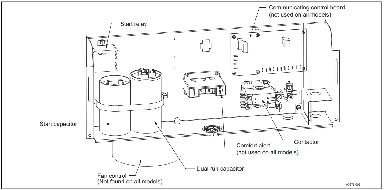
Figure 2: Applicable models HC6B to YZH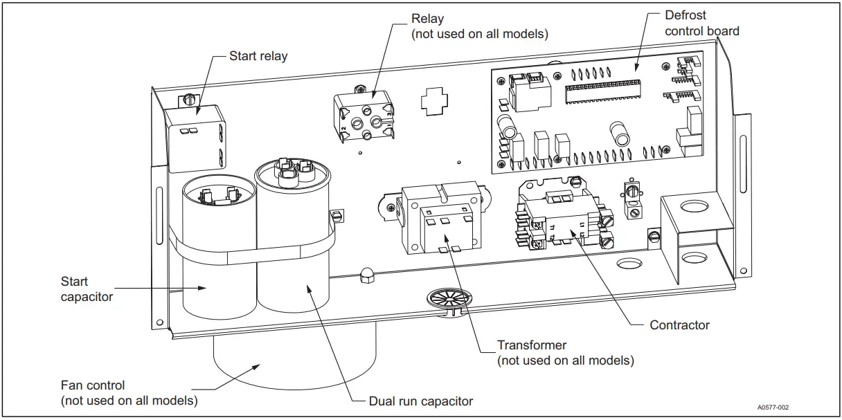
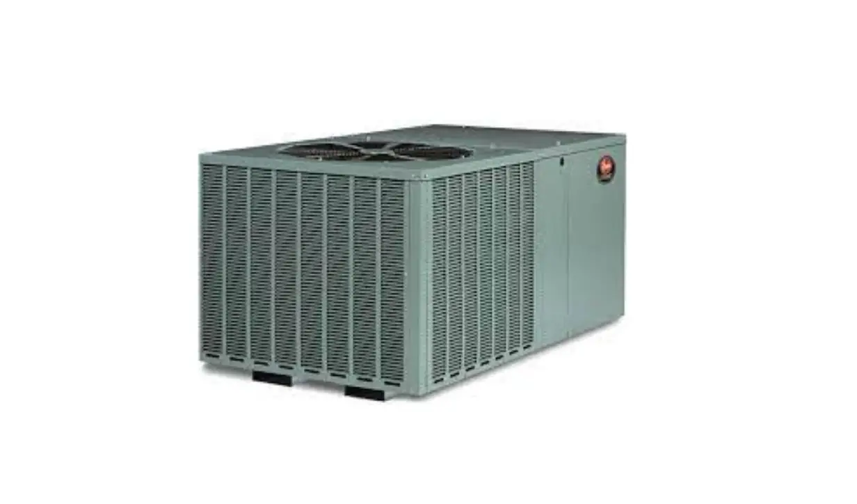
Figure 3: Applicable models CCJD to YCJF
Figure 4: Applicable models CHJD to YHJR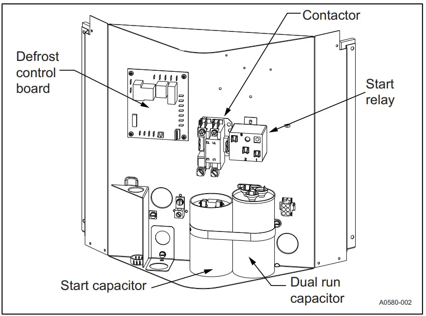
Figure 5: Applicable models TCHE to YCHD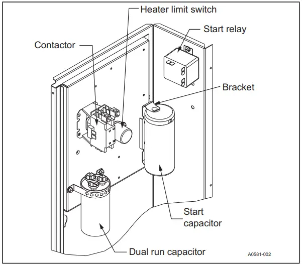
Figure 6: Applicable models TCHE to YCHD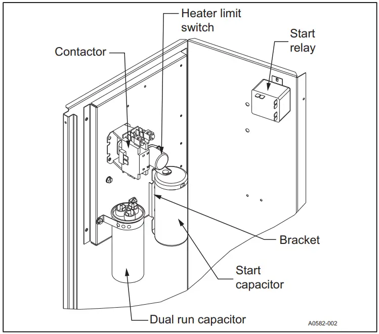
Figure 7: Applicable models CC7B to YFE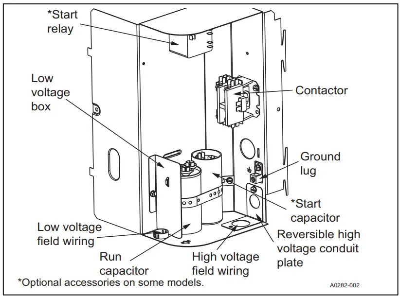
Figure 8: Applicable models CC7B to YFE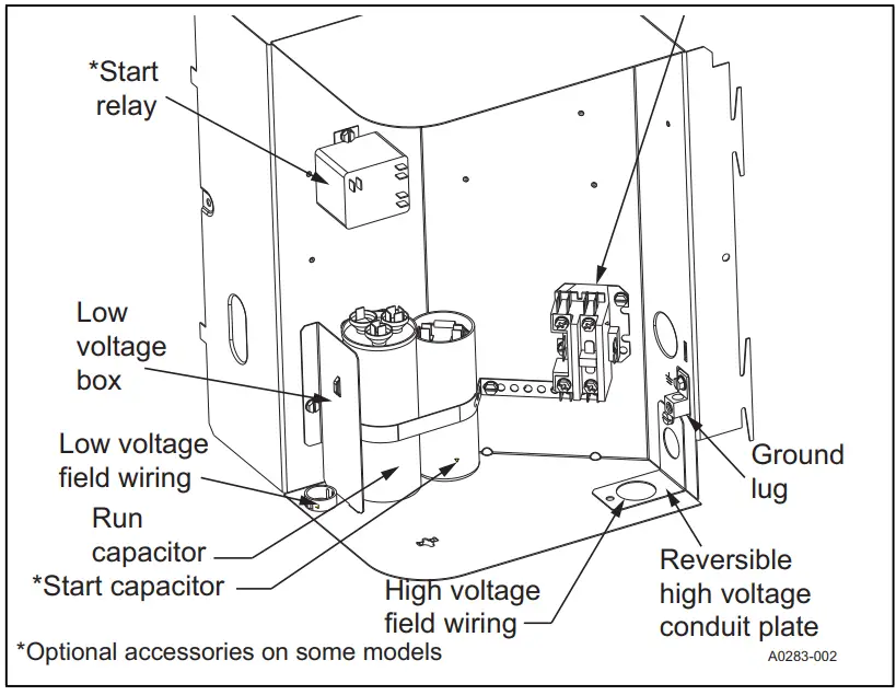
Figure 9: Applicable models CH6B to YHG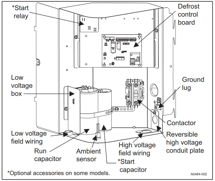
Figure 10: Applicable models CH6B to YHG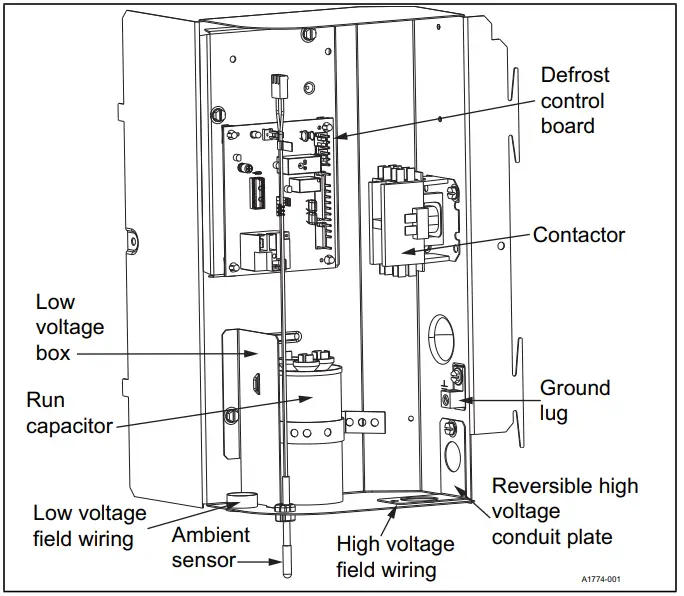
Figure 11: Applicable models AC19 to YZT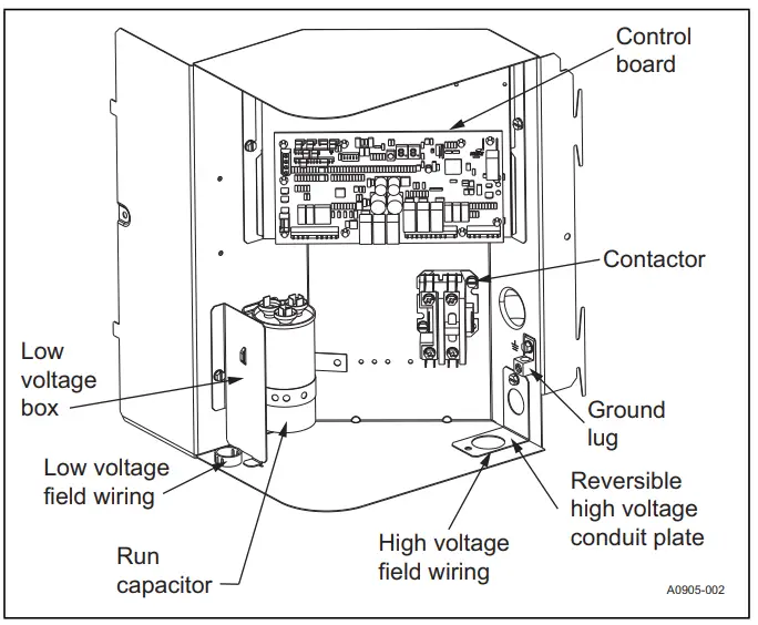
Wiring diagram
Figure 12: Universal wiring diagram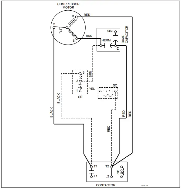
Subject to change without notice. Published in U.S.A. 5006452-UAI-H-0522
Copyright © 2022 by Johnson Controls. All rights reserved. Supersedes: 5006452 UAI-G-0921
York International Corp. 5005 York Drive Norman, OK 73069


