![]() SWIMMING POOL HEAT PUMP
SWIMMING POOL HEAT PUMP
 Installation & Instruction Manual
IMPORTANT NOTE:
Thank you very much for purchasing our product. Before using your unit, please read this manual carefully and keep it for future reference.
FOREWORD
Statement
To keep users and property under safe operating conditions, please follow the instructions below:
- Wrong operation may result in injury or damage;
- Please install the unit in compliance with local laws, regulations and standards;
- Confirm power, voltage and frequency – NE55 Requires permanent 240Volt, 1 Phase, 60HZ Connection;
- The unit must be permanently connected to the power supply by a qualified electrician according to local rules and regulations.
- Independent power disconnect switch must be installed with the unit per local laws and regulations.
Safety Factors
The following safety factors need to be considered:
- Please read the following warnings before installation.
- Be sure to check the details that need attention, including safety related warnings.
- After reading the installation instructions, be sure to save them for future reference.
Warning
Make sure that the unit is installed safely and is properly secured to a suitable base If the unit is not secured or installed properly, it may cause damage to the unit and surrounding area.
Unit must be installed outdoors in a well ventilated or open area.
- Use the correct gauge wire determined by an electrician per local regulations and fasten it to the terminal block supported in a manner that there ensures no strain on the components or wiring.
- Improper wiring may cause injury or fire.
Please connect power wire according to the wiring diagram in the manual to avoid fire or damage to the unit. - Be sure to use approved materials during installation. Wrong parts or wrong materials may result in fire, electric shock, or the unit falling or tipping over.
- Install on the ground safely and properly secured, please read installation instructions.
Improper installation may result in fire, electric shock, tipping of the unit, or water leaking. - Use professional tools for the electrical connections. If power supply capacity is insufficient or circuit is not completed, it may cause fire or electric shock.
- The unit must have grounding device. If power supply does not have grounding device, do not connect the unit.
- The unit should only be removed or repaired by a professional technician.
Improper movement or maintenance of the unit may cause water leakage, electric shock, or fire. - Don’t connect or disconnect unit without first disconnect the power at the breaker or power disconnect. It may cause fire or electric shock.
- Don’t touch or operate the unit when your hands are wet. It may cause fire or electric shock.
- Do not let water permeate into the electrical components.
Warning
- Do not install the unit in a location where there may be flammable gas.
- If there is flammable gas near the unit, it may cause an explosion.
- Do not clean the unit while power is on. Disconnect power at the circuit breaker before cleaning the unit. Not disconnecting the power may result in injury from a running fan or electric shock.
- Stop operating the unit when there is a problem or a fault code.
- Be careful when the unit is unpacked and not yet installed. Pay attention to sharp edges and to the fins of the heat exchanger.
- After installation or repair, please confirm refrigerant is not leaking. If there is not enough refrigerant, the unit will not work properly.
- Don’t put your fingers into fan or evaporator. Touching a running fan may result in serious injury.
- This appliance is not to be used by persons (including children) with reduced physical, sensory or mental capabilities, or lack of experience and knowledge, unless they have been given supervision or instruction a professional technician. Children must use it under the supervision of an adult to ensure that they use the appliance safely. If the power wire is damaged, it must be replaced by a professional technician to avoid danger.
OVERVIEW OF THE UNIT
Accessories Supplied with the Unit
After unpacking, please check if you have all the following components.
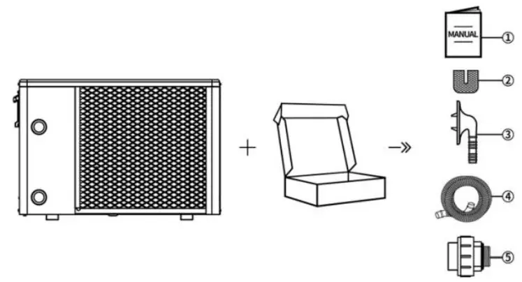
| NO. | Components | Quantity | NO. | Components | Quantity |
| 1 | User Manual | 1 | 4 | Drain Pipe | 1 |
| 2 | Rubber Blanket | 4 | 5 | Water Pipe Joint | 2 |
| 3 | Drain Connector | 1 |
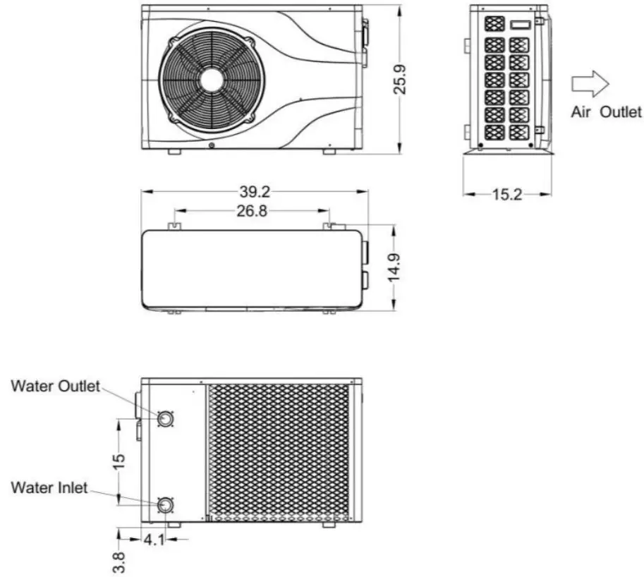
Dimensions of the Unit
Model: NE55
Main Parts of the Unit
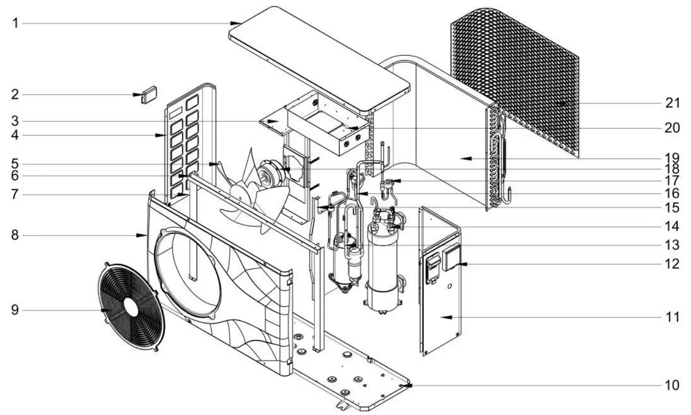
| 1 | Top cover | 8 | Front plate | 15 | Middle plate |
| 2 | Left handle | 9 | Fan motor cover | 16 | Pipe component |
| 3 | Motor support | 10 | Chassis | 17 | EEV |
| NI* | Left plate | 11 | Right plate | 18 | Fan motor |
| 5 | Fan blade | 12 | Wire controller | 19 | High efficiency finned heat exchanger |
| 6 | Fixed plate 1 | 13 | Compressor | 20 | Electrical box |
| 7 | Fixed plate 2 | 14 | Titanium heat exchanger | 21 | Back net |
SPECIFICATIONS
| Model | NE55 |
| Power supply(V/Ph/Hz) | 208-230V—/60Hz |
| Rated Ambient Temp Range (°F) | 23-104 |
| ‘Heating Capacity (Btu/h) — 80/80/80 | 55000 |
| ‘COP | 6.0 |
| 2Heating Capacity (Btu/h) – 50/63/80 | 35000 |
| 2COP | 4.0 |
| Maximum Water Outlet Temp. (°F) | 104 |
| Rated Water Flow (gpm) | 24. |
| Rated Water Pressure Drop (psi) | 4. |
| Maximum Input Power (kBtu/h) | 14.0 |
| Fan Motor Rating Load (FLA) (A) | 0.4 |
| Fan Motor Horsepower (Hp) | 1/8HP |
| Compressor Rated Load RLA (A) | 16. |
| Compressor Lock Rotor Amperage (LRA) (A) | 86 |
| Minimum Circuit Ampacity (A) | 19. |
| Breaker Size MIN/MAX (A) | 20A/30A |
| Refrigerant Quantity (Ibs) | R410A/3.417 |
| Dry Weight (Ibs) | 135. |
| Net Dimensions WXDXH (inches) | 39.2×15.2×25.9 |
| Water Pipe Connection | 1.5 Inch Quick Connect |
| Water Proof Class | IPX4 |
| Electricity Shock Proof Class | I |
| Refrigerant Side Pressure Limits (psi) | 638/217 |
| Water Side Pressure Limits (psi) | 100 psi |
The technical specifications of our heat pumps are provided for information purposes only. We reserve the right to make changes without notice.
INSTALLATION
WARNING: The heat pump must be installed by a qualified technician. Improper installation, adjustment, service, maintenance or use can cause fire, electrical shock or other conditions which may cause injury or property damage.
This section is provided for information purposes only and must be adapted according to the actual site conditions.
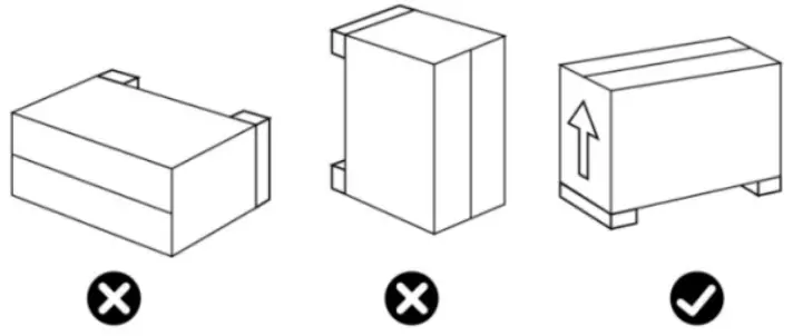
Transportation
- When storing or moving the heat pump, the heat pump should be in an upright position. Never Tilt the unit more than 30 degrees.

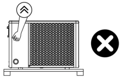
- When moving the heat pump, do not lift it by the water unions as this may damage the titanium heat exchanger inside the heat pump.

Notice Before Installation
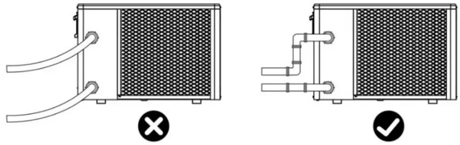
- The water unions are not designed to support the weight of unsupported flexible tubing. The heat pump must be connected with properly supported tubing that does not pull or strain on the heat pump unions!

- To ensure heating efficiency, the length of the piping between the pool and the heat pump should be less than 30ft.
Installation Instructions
3.3.1 Pre-requirements
Equipment necessary for the installation of your heat pump:
- Power supply cable suitable for the unit’s power requirements and compliant with your local regulations.
- A By-Pass kit, sufficient PVC tubing suitable for your installation, as well as PVC , PVC adhesive and sandpaper.
- A set of wall plugs and expansion screws suitable to attach the unit to your support or base.
- We recommend that you connect the unit to your installation by means of well supported flexible PVC pipes to reduce the transmission of vibrations.
- Suitable fastening studs may be used to raise the unit.
Heat Pump Installation
- The heat pump must be fixed using bolts (M10) to a concrete foundation or suitable brackets.
The concrete foundation must be solid; the brackets must be strong enough and treated against corrosion. - The heat pump needs a water pump (Supplied by the user). Max. lift 30ft;
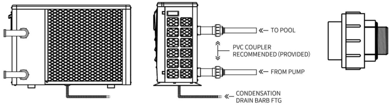
- When the heat pump is running, there will be condensate water discharged from the bottom that must be properly managed and directed away from the heat pump. Please insert the drainage tube (accessory) into the hole and clip it in properly, then connect a pipe to drain the condensate water away. Install the heat pump, at least 3” off the ground with solid, water-resistant pads, then connect the drainage pipe to the opening located under the heat pump.
Location and Size
Please comply with the following rules concerning the choice of heat pump location.
- The unit’s location must be easily accessible for convenient operation and maintenance.
- It must be installed on the ground, fixed ideally on a level concrete floor. Ensure that the floor is sufficiently stable and can support the weight of the unit.
- A water drainage device must be provided close to the unit in order to protect the area where it is installed.
- If necessary, the unit may be raised by using suitable mounting pads designed to support its weight.
- Check that the unit is in a properly ventilated area, that the air outlet is not facing the windows of neighboring buildings and that the exhaust air cannot return to the heat pump. In addition, provide sufficient space around the unit for servicing and maintenance operations.
- The unit must not be installed in an area exposed to oil, flammable gases, corrosive products, sulfur compounds or close to high frequency equipment.
- To prevent external damage to the unit, do not install it near a road or track.
- To avoid causing nuisance to neighbors, make sure the unit is installed in an area that is not sensitive to noise.
- Keep the unit out of the reach of children.
- Installation space:
Unit: mm
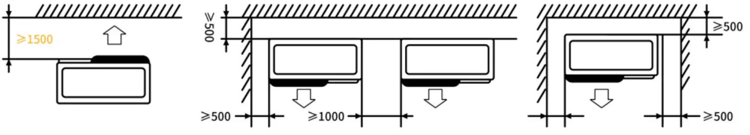
Do not put anything less than 1500mm (5ft) in front of the heat pump.
Leave 500mm (2ft) of empty space on the sides and back of the heat pump and free space for air circulation above
Do not leave any obstacles above or in front of the device!
Installation Layout
The installation diagram is shown in the following figure: Pool → Pump → Filter → Heat Pump → Sanitizer → Return to Pool:
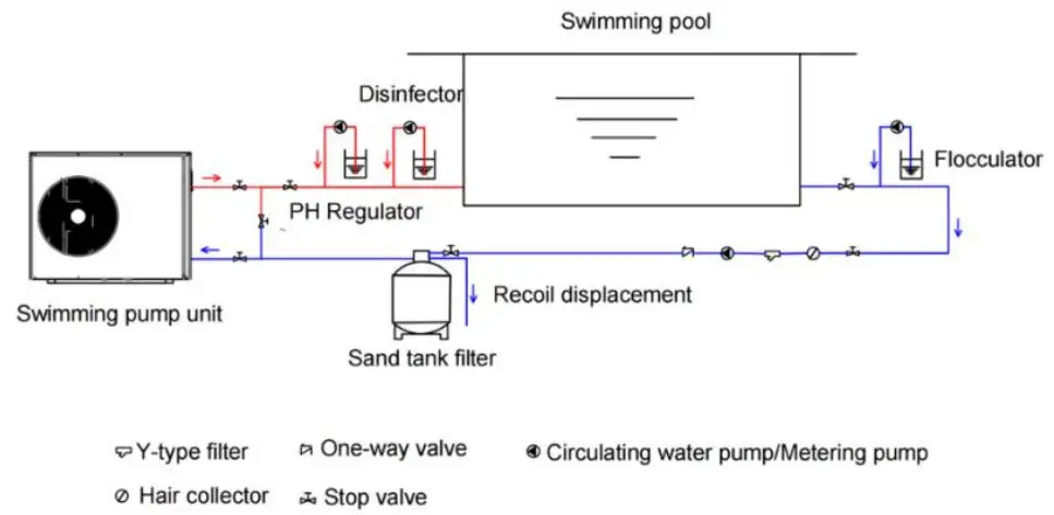
| No. | Item | Quantity | No. | Item | Quantity |
| 1 | Swimming Pump Unit | 1 | 7 | PH Regulator | 1 |
| 2 | Y-Type Filter | 1 | 8 | Sand Tank Filter | 1 |
| 3 | One-Way Valve | 1 | 9 | Flocculator | 1 |
| 4 | Circulating Water Pump | 1 | 10 | Disinfector | 1 |
| 5 | Hair Collector | 1 | 11 | Metering Pump | 3 |
| 6 | Stop Valve | 7 |
Notice: The filter must be cleaned regularly to ensure that water in the system is clean and to avoid lack of water flow. It is necessary that a drainage valve is fixed at the lowest point in the lower water pipe to completely drain water out of the system for winterizing. If the unit is not running during winter months, please disconnect power supply and drain water from the unit through the drainage valve or by disconnecting the quick connect fittings. If unit is used at ambient temperatures below 0℃, please keep ensure that the water pump continuously runs to avoid water freezing inside the machine.
Electrical Installation
To function safely and maintain the integrity of your electrical system, the unit must be connected to your electrical supply in accordance with the following regulations:
- The heat pump must be connected to a suitable circuit breaker in accordance with current standards and regulations in the country where the system is installed.
- The electrical supply cable must be adapted to match the unit’s rated power and the length of wiring required for the installation. The cable must be suitable for outdoor use.
- In places open to the public, or where required by law, an emergency stop button or power disconnect switch should be installed near the heat pump.
Power Supply Wire Size
| Model | Power Supply Wires | ||
| Electrical Supply | Cable Diameter | Specification | |
| NE55 | 208-230V—/60Hz | selected by electrician | selected by electrician |
Electrical Connection
WARNING: Power supply must be disconnected before performing any work on the heat pump.
Please comply with the following instructions to connect the heat pump.
Step 1: Detach electrical side panel with a screwdriver to access electrical terminal block.
Step 2: Insert cable into the heat pump unit port.
Step 3: Connect power supply cable to terminal block according to the diagram below.
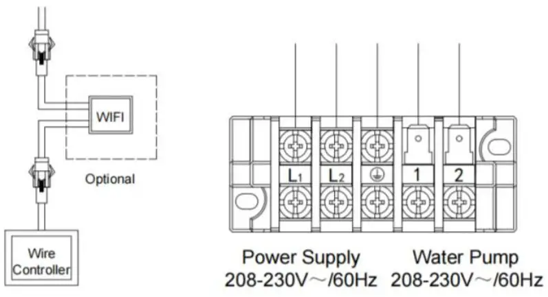
Note: If the water pump wattage is more than 800 Watts, Do Not Connect it to the terminal block inside the heat pump. Use an external contactor, and a separate breaker
Commissioning the heat pump after Installation:
WARNING: Please check all the wiring carefully before turning on the heat pump.
3.4.1 Inspection Before First Trial Run
Before performing initial functional test, confirm below items and write √ in block;
| ❑ | Correct unit installation |
| ❑ | Power supply voltage is the same as unit rated voltage |
| ❑ | Correct piping and wiring |
| ❑ | Air inlet & outlet port of unit are unblocked |
| ❑ | Drainage and venting are unblocked and there are no water leaks |
| ❑ | GFCI Breaker / Current Leakage protector are working (If required by local regulations) |
| ❑ | Ground wire / bonding wire are connected correctly |
Trial Run:
Step 1: Run test can begin after completing the installation;
Step 2: All wiring and piping should be connected well and carefully checked, then start circulating the water before power is switched on;
Step 3: Empty all air within the water circulation pipes, then press the “on-off” button on the control panel to run the unit at the temperature setting;
Step 4: Items that need to be checked during the commissioning test:
- Check that unit current is normal per nameplate specifications;
- Check that each button on the control panel functions normally;
- Check that the screen is displaying information normally and that there are no error codes;
- Check for any water leaks in the circulation system;
- Check that the Condensate drain is not obstructed;
- Check for any abnormal sounds or vibrations?
- Check that heat pump shuts off on a water flow error as soon as the water pump is turned off
REMOTE CONTROLLER OPERATION GUIDANCE
Control Panel Diagram
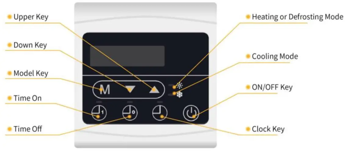
Basic Icons
- When in heating mode, “
 ” light up;
 - When in Cooling mode, “
 ” light up;
 - When in defrost mode, “ ” flash.
- When the unit is on, it displays an error code if an error is detected, and it displays water inlet temperature if there are no errors.
- When the unit is off, it displays an error code if an error is detected, and it displays current time if there are no errors.
Key Operating Instructions
| No. | Item | Operation Way |
| 1 | ON/OFF | At the main interface, press ” |
| 2 | Check System Status | Pressing ” |
| 3 | Select Mode | In the start-on state, press ” M ” to select mode between Heating mode, Cooling mode, and Automatic mode. |
| 4 | Set Temperature | In the start-on state, press “ |
| 5 | Set Clock | Press “ hour part flashes. Press ” ” time setting. |
| 6 | Time On | Press on the main interface to enter “time on” hour setting. The hour part will flash. Press “ |
| 7 | Time Off | Press ” part will flash. Press ” |
| 8 | Exit Interface | In other menus, press ” |
| 9 | Fahrenheit / Celsius Switch | |
| In the shutdown state, press ” |
System Status
| Code | Meaning | Range | Remarks |
| 1 | Water inlet temp. | -9-99-C (161:-210-F) | Measured |
| 2 | Water outlet temp. | -9-99°C (16°F-210°F) | Measured |
| 3 | Coil temp. | -9-99°C (16°F-210°F) | Measured |
| 4 | Exhaust temp. | 0-125°C(0-257°F) | Measured |
| 5 | Ambient temp. | -9-99°C (16°F-210°F) | Measured |
| 6 | Suction temp. | -9-99°C (16°F-210°F) | Measured |
| 7 | Cooling coil Temp. | -9-99°C (16°F-210°F) | Measured |
| 8 | EEV steps | 0-48 | Actual Value=10* Displayed Value |
Trouble Shooting
| Code | Description | Trouble shooting |
| P3 | Water inlet temp. sensor failure | Check the sensor connection, change the sensor if necessary. |
| P4 | Water outlet temp. sensor failure | Check the sensor connection, change the sensor if necessary. |
| P1 | Coil temp. sensor failure | Check the sensor connection, change the sensor if necessary. |
| P7 | Ambient temp. sensor failure | Check the sensor connection, change the sensor if necessary. |
| P2 | Exhaust temp. sensor failure | Check the sensor connection, change the sensor if necessary. |
| P8 | Excessive low temp. of water outlet when cooling | No Action Needed, this is a protection feature and unit will restart when necessary |
| E2 | Excessive temperature difference of water inlet and water outlet protection | 1.Replace exhaust temperature sensor. 2.Replace PCB control board. 3.HVAC Service Technician must check whether there is a refrigerant system leak. If refrigerant leak is found, repair the leak point, vacuum unit, then recharge the refrigerant according to the type and weight of the refrigerant on the nameplate. |
| PC | Winter level 1 frost protection | No User Action Needed, this is a protection function |
| PC | Winter level 2 frost protection | No User Action Needed, this is a protection function |
| E4 | System high pressure failure | 1.Check Water Flow. Clean the Pool filter 2.Check the inlet/outlet water temperature. Ensure heat exchanger is not clogged. 3.Replace the high-pressure switch. |
| P9 | System low pressure failure | 1.Ambient temperature too low; <32f 2.Heat exchanger Dirty/Clogged. Carefully clean the fins. 3.Contact HVAC Service Tech as there might be a refrigerant circuit blockage or refrigerant leak; |
| PL | Water flow failure | Check that there is Water Flowing through the Heat Pump. Backwash / Clean Pool Fitter Check water flow switch, change the switch if necessary. |
| P6 | Excessive temperature difference between water inlet and water outlet | Check whether the water flow meets the nameplate requirements. Backwash / Clean Filter |
| E3 | High exhaust temperature protection | 1.Replace exhaust temperature sensor. 2.Replace PCB control board. 3.Contact Service to Check for a refrigerant circuit leak. If there is a refrigerant leak, repair the leak, vacuum unit, charge the refrigerant according to the type and weight of the refrigerant on the nameplate. |
| E8 | Communication failure | (Available for remote controller ONLY) 1.Check if the communication connection wire between display and PCB is well . 2.Change or mend the wire if necessary . 3.Check the PCB or display. If damaged, Change the corresponding part . |
| E5 | Cooling coil temp. sensor failure | Check the sensor connection, change the sensor if necessary. |
| E6 | Suction temp. sensor failure | Check the sensor connection, change the sensor if necessary. |
MAINTENANCE AND WINTERIZING
Maintenance
WARNING: Before undertaking maintenance work on the unit, ensure that you have disconnected the electrical power supply.
- Cleaning
a. The heat pump’s casing must be cleaned with a damp cloth. The use of detergents or other household products could damage the surface of the casing and affect its properties.
b. The evaporator at the rear of the heat pump must be carefully cleaned with a vacuum cleaner and soft brush attachment. - Annual maintenance
The following operations must be undertaken by a qualified person at least once a year.
a. Carry out safety checks.
b. Check the integrity of the electrical wiring.
c. Check the grounding/bonding connections.
d. Monitor the condition of the pressure gauge and the presence of refrigerant.
Winterizing
“CUT OFF” power supply to the heater before cleaning, examination and repairs
In winter season when you don’t swim:
a. Cut off power supply to prevent any machine damage.
b. Drain water out of the machine.
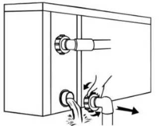
!! Important:
Unscrew the water inlet pipe fitting to let the water flow out of the unit. If water freezes in the machine during the winter season, the titanium heat exchanger may be damaged.
c. Cover the machine body when not in use.
NIRVANA HEAT PUMP INC
4215 Rue St-Joseph
Trois-Rivieres, QC, G8Z 4G3
Tel Canada: (819) 519-8970
Tel USA: (844) 447-7665
www.nirvanahp.com


