HYDRO 7024510 Swimming Pool Heat Pump
![]() READ THIS MANUAL CAREFULLY BEFORE STARTING UP THE UNIT. DO NOT THROW IT AWAY. KEEP IT IN YOUR FILES FOR FUTURE REFERENCE.
READ THIS MANUAL CAREFULLY BEFORE STARTING UP THE UNIT. DO NOT THROW IT AWAY. KEEP IT IN YOUR FILES FOR FUTURE REFERENCE.
![]() BEFORE OPERATING THE UNIT, MAKE SURE THE INSTALLATION HAS BEEN CARRIED OUT CORRECTLY BY A PROFESSIONAL DEALER. IF YOU FEEL UNSURE ABOUT OPERATION, CONTACT YOUR DEALER FOR ADVICE AND INFORMATION
BEFORE OPERATING THE UNIT, MAKE SURE THE INSTALLATION HAS BEEN CARRIED OUT CORRECTLY BY A PROFESSIONAL DEALER. IF YOU FEEL UNSURE ABOUT OPERATION, CONTACT YOUR DEALER FOR ADVICE AND INFORMATION
INTRODUCTION
This manual
This manual includes the necessary information about the products. Please read this manual carefully before you use and maintain the product.
The unit
The swimming pool heat pump is one of the most economical systems to heat the swimming pool efficiently. Using the free renewable energy from the air and the earth, it delivers up to five times more energy in heating than the traditional heating systems such as gas boiler and electric heater. So you will save 4/5 costs of the traditional heating. The swimming pool heat pump can lengthen your swimming season, and gives you comfort at high level. You will enjoy swimming not only in summer, but also in spring, autumn and even winter time.
Features
- Ecological and economical heating
Using the renewable energy from the outdoor air, it consumes less energy with low carbon emission. Use advanced environmental friendly refrigerant R32 without destroying on Ozone. - Titanium heat-exchanger
Advanced titanium heat-exchanger guarantees long life spans of heat pump free from corrosion and rust. By using of titanium heat-exchanger, the heat pump could be applied with all types of water treatment such as chlorinate, iodine, bromine and salt water. - Multiple functions
- Heating functions available;
- Auto operating, Auto-restart;
- Timer on/off: no human attendance is required;
- Wide ambient running range: 10°C to 43°C.
- Reliable operation
To guarantee the stable running and the safety of the products, multiple protection devices have been set into the pool heat pumps which include water flow protection, high and low pressure protections, overload protection, etc. - Safe using
The swimming pool heat pump works without oil, gas or other hazardous substance. So adopting heat pump to heat your swimming pool, it can avoid potential risk. Moreover there are no gas connections, and fuel tank is also no need. No risk of intoxication, smell or pollution because of gas and fuel leakage. - Self-diagnosis
When there is malfunction, the swimming pool heat pump will make self-diagnosis automatically and will display error code in the controller screen. The code could be found at a glance.
SAFETY INSTRUCTIONS
To prevent injury to the user, other people, or properties damage, the following instructions must be followed. Incorrect operation due to ignoring of instructions may cause harm or damage.
Install the unit only when it complies with local regulations, by-laws and standards. Check the main voltage and frequency. This unit is only suitable for earthed sockets, connection voltage 220 – 240 V~, 1Ph, 50Hz.
The following safety precautions should always be taken into account:
- Be sure to read the following WARNING before installing the unit.
- Be sure to observe the CAUTIONS specified here as they include important items related to safety.
- After reading these instructions, be sure to keep it in a handy place for the future reference.
![]() WARNING
WARNING
Do not install the unit by yourself.
Incorrect installation could cause injury due to fire, electric shock, the unit falling and leakage of water. Consult the dealer from whom you purchased the unit or a specialized installer.
Install the unit securely in a place.
When insufficiently installed, the unit could fall causing injury. When installing the unit in a small room, please take measures (like sufficient ventilation) to prevent the asphyxia caused by the leakage of refrigerant.
Use the specified electrical wires and attach the wires firmly to the terminal board (connection in such a way that the stress of the wires is not applied to the sections).
Incorrect connection and fixing could cause a fire.
Be sure to use the provided or specified parts for the installation work.
The use of defective parts could cause an injury due to possible fire, electric shocks, the unit falling etc.
Perform the installation securely and please refer to the installation instructions.
Incorrect installation could cause an injury due to possible fire, electric shocks, the unit falling, leakage of water etc.
Perform electrical work according to the installation manual and be sure to use a dedicated section.
If the capacity of the power circuit is insufficient or there is an incomplete electrical circuit, it could result in a fire or an electric shock.
The unit must always have an earthed connection.
If the power supply is not earthed, you may not connect the unit.
Never use an extension cable to connect the unit to the electric power supply.
If there is no suitable, earthed wall socket available, it should be installed by a recognized professional electrician.
Do not move and repair the unit by yourself.
Before proceeding with any maintenance, service or repairing work, the product must be isolated from the mains electrical supply. Only qualified personnel could carry out these tasks. Improper movement or repairing the unit could lead to water leakage, electrical shock, injury or fire.
![]() CAUTION
CAUTION
Do not install the unit in a place where there is a chance of flammable gas leaks.
If there is a gas leak and gas accumulates in the area surrounding the unit, it could cause an explosion.
Perform the drainage/piping work according to the installation instruction.
If there is a defect in the condensing water drainage or water pipes, water could be leaked from the unit and household goods could get wet and be damaged.
Do not clean the unit when the power is switched on.
Always shut off the power when cleaning or servicing the unit. If not, it could cause an injury due to the high speed running fan or an electrical shock.
Do not continue to run the unit when there is something wrong or there is a strange smell.
The power supply needs to be shut off to stop the unit; otherwise this may cause an electrical shock or fire.
Do not put your fingers or others into the fan, or evaporator.
The ventilator runs at high speed, it could cause serious injury.
ACCESSORIES
Before starting the installation, please make sure that all accessories are collected from the unit package:
| Packing list | ||
| Item | Image | Quantity |
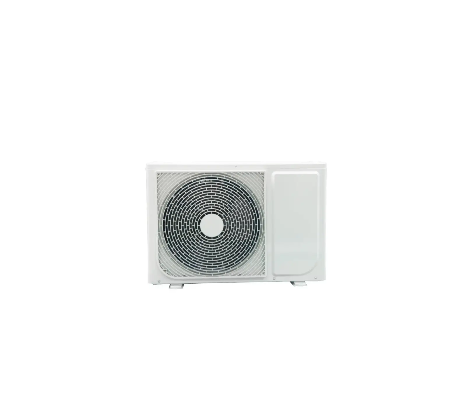
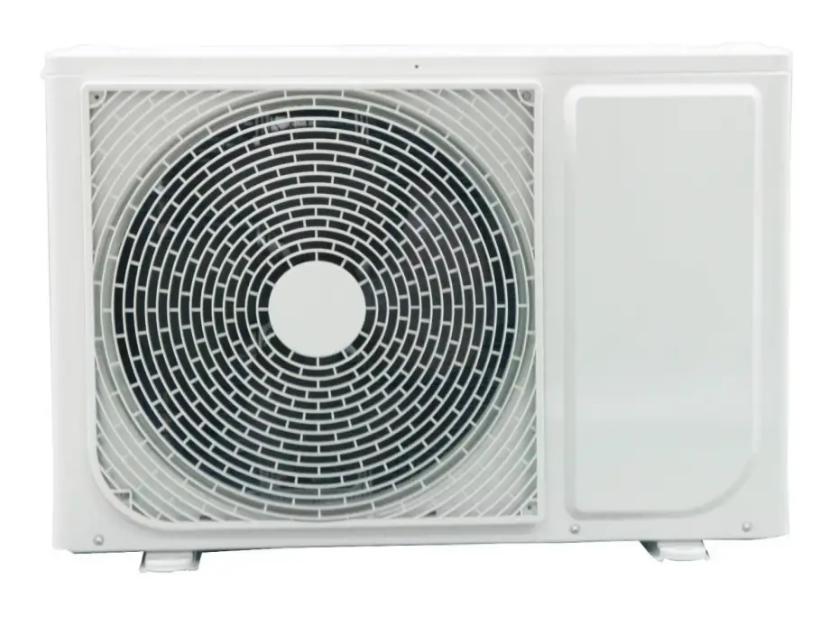
| Swimming pool heat pump | 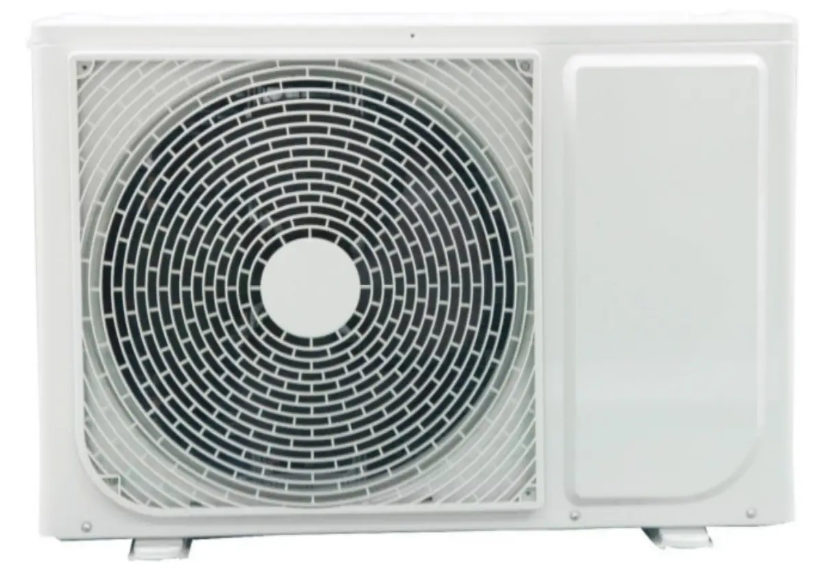 | 1 |
| Operation and Installation Manual | This manual | 1 |
| Inlet and outlet water pipe connectors | 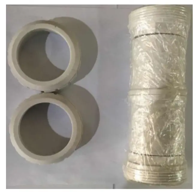 | 1 |
| Condensing water drainage pipe | 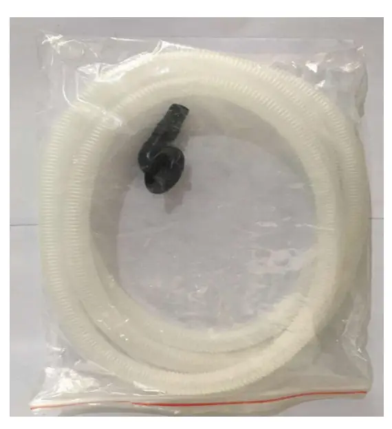 | 1 |
DIMENSIONS
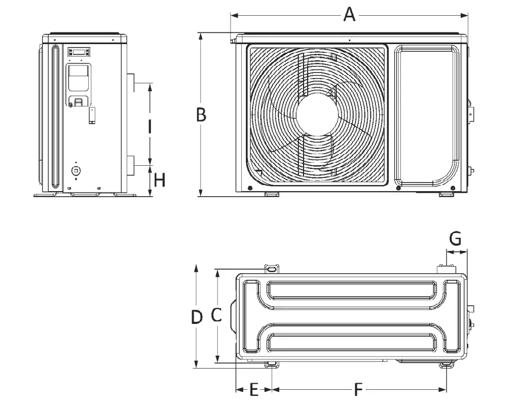
| A5/32 | A7/32 | A10/32 | A13/32 | |
| A | 816 | 816 | 912 | 912 |
| B | 556 | 556 | 718 | 718 |
| C | 315 | 315 | 375 | 375 |
| D | 352 | 352 | 425.5 | 425.5 |
| E | 124 | 124 | 135 | 135 |
| F | 600 | 600 | 624 | 624 |
| G | 71 | 71 | 96 | 96 |
| H | 105 | 105 | 121 | 121 |
| I | 280 | 280 | 370 | 370 |
EXPLODED VIEW
Model: A5/32, A7/32
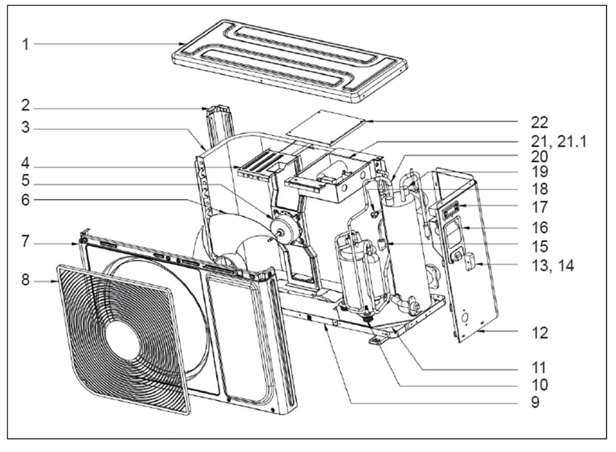
| No. | Name | Qty |
| 1 | Top cover | 1 |
| 2 | Column | 1 |
| 3 | Air side heat-exchanger | 1 |
| 4 | Motor bracket | 1 |
| 5 | Motor | 1 |
| 6 | Axial fan | 1 |
| 7 | Front panel | 1 |
| 8 | Grille | 1 |
| 9 | Chassis | 1 |
| 10 | Compressor | 1 |
| 11 | Fixing plate | 1 |
| 12 | Right panel | 1 |
| 13 | Wires clip | 1 |
| 14 | Wires clip | 1 |
| 15 | Low pressure switch | 1 |
| 16 | Handle | 1 |
| 17 | Controller | 1 |
| 18 | Needle valve | 1 |
| 19 | Water flow switch | 1 |
| 20 | Titanium heat-exchanger | 1 |
| 21 | E-box ass’y | 1 |
| 21.1 | Capacitor | 1 |
| 22 | Cover, E-box | 1 |
Model: A10/32, A13/32
| No. | Name | Qty |
| 1 | Top cover | 1 |
| 2 | Cover, E-box | 1 |
| 3 | Air side heat-exchanger | 1 |
| 4 | Motor bracket | 1 |
| 5 | Motor | 1 |
| 6 | Axial fan | 1 |
| 7 | Front panel | 1 |
| 8 | Grille | 1 |
| 9 | Right panel, front | 1 |
| 10 | Chassis | 1 |
| 11 | Compressor | 1 |
| 12 | Fixing plate | 1 |
| 13 | Right panel | 1 |
| 14 | Handle | 1 |
| 15 | Low pressure switch | 1 |
| 16 | Controller | 1 |
| 17 | Titanium heat-exchanger | 1 |
| 18 | Water flow switch | 1 |
| 19 | Needle valve | 1 |
| 20 | E-box ass’y | 1 |
| 20.1 | Capacitor | 1 |
| 20.2 | Capacitor | 1 |
INSTALLATION
Installation information
The following information given here is not an instruction, but simply meant to give the user better understanding of the installation.
Condition of installation
The following information given here is not an instruction, but simply meant to give the user a better understanding of the installation.
Installation place
Install the swimming pool heat pump on a flat, horizontal, and stable surface. Maintain 1m of open space in front of the grille and 3m on the outlet side of the ventilator. And reserve enough space to allow access to operate controller. Make sure that the outlet air will not be breathed in.
To perfect your installation
- Avoid directing the flow of ventilated air towards a sensitive noise zone, such as room’s window.
- Avoid positioning pool heat pump on a surface that can transmit vibrations to dwelling.
- Try to avoid placing appliance under a tree or exposed to water or mud, which would be likely to complicate maintenance.
Water connection
- The heat pump is connected to a filtration circuit with a by-pass.
- It is imperative that the by-pass is placed after the pump and the filter.
- The by-pass generally consists of 3 valves.
- This makes it possible to regulate the water flow which passes through the heat pump and to isolate the heat pump completely for any maintenance work, without cutting the flow of filtered water.

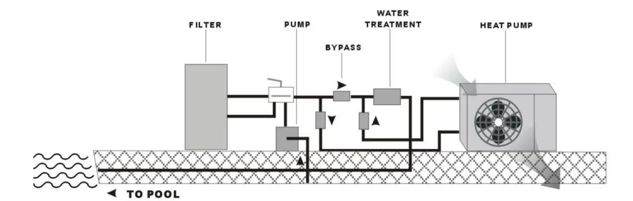
If your installation is equipped of the water treatment with product adductions (e.g. chlorine, brominates, salt…) the by-pass must be installed before the water treatment, with a non-return valve between the by-pass and water treatment.
Electrical connection
- Electrical supply must correspond to that indicated on the appliance.
- Connection cables have to be sized according to appliance power and installation requirements
Please refer to below table:
| Heat pump | Cable size |
| A5/32, A7/32 | 3×1.5mm2 |
| A10/32, A13/32 | 3×2.5mm2 |
- These data are only indication, you must ask an electrician to determine the exact data for your pool installation.
- Use the cable glands and grommets provided inside the heat pump to route cables
STARTING UP FOR THE FIRST TIME
After all the connections have been made and checked, the following steps must be taken:
- Turn on the filter pump. Check for leaks and make certain that the water flows from and to the swimming pool.
- Connect the power supply to the heat pump and press the ON/OFF button. The appliance will start up after the time delay (see below) has elapsed.
- After a few minutes check whether the air being expelled from the appliance is cooler.
- Leave the appliance and filter pump in operation 24 hours per day until the desired water temperature has been reached. At this point the heat pump ceases operation. The appliance will now start up again automatically (as long as the filter pump is in operation) whenever the swimming pool temperature falls to 1 degree below the programmed temperature.
Depending on the initial temperature of the swimming pool water and the air temperature, several days may be needed to bring the water up to the temperature required. Covering the swimming pool properly can considerably shorten this period.
Time Delay – the appliance is fitted with built-in start-up delay of 3 minutes as protection for the electronics and to increase the life of the contacts. After this interval, the appliance will restart automatically. Even a brief interruption in the flow of current will activate this delay and thus prevent the appliance from starting up immediately. Additional interruptions in the current during this delay will have no influence on the 3-minute countdown.
CONTROLLER
Display and Operation Surface
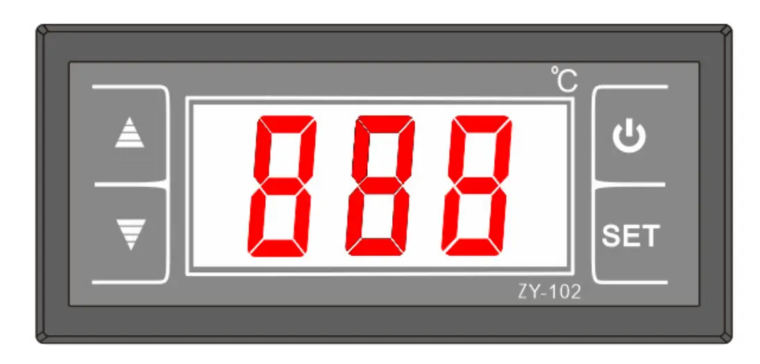
Definitions
No. | Symbol | Function | Description |
| 1 |  | Unit power on/off | In normal working status, hold this key for 5s to power off the unit. In power-off status, hold this key for 5s to enter normal working status of the unit. In setting or query interface, press this key to exit the interface and store corresponding parameters. |
| 2 | SET | Confirmation Record query |
|
| 3 | UP | Parameter value increase; Menu item switch |
|
| 4 | DOWN | Parameter value |
|
| decrease; Menu item switch | 3. In the parameter setting interface, press this key to decrease the parameter value. |
Note: The system exits to the home screen if no key is pressed within 10s in the parameter query or setting interface. Any parameter change will be automatically saved.
SPT setting
On the home screen (on/off status), press “UP” and “DOWN” to adjust the set temperature SPT.
Press ” ![]() ” to exit SPT setting with the configuration saved.
” to exit SPT setting with the configuration saved.
The adjustable range of SPT is determined by the lower temperature limit (SPTL) and upper temperature limit (SPTH).
| No. | Parameter | Function | Value Range | Default Value |
| 1 | SPT | Target temperature control | {SPTL,SPTH} | 25 |
Parameter query
Press “SET” to enter the parameter query interface, and press “UP” and “DOWN” to check parameters.
| No. | Parameter | Description |
| 1 | Return water temperature | Outdoor ambient temperature; –30°C to +70°C |
| 2 | Ambient temperature | Condenser pipe temperature; –30°C to +70°C |
| 3 | Load startup signal | Value “0” indicates load disabled, while value “1” indicates load enabled. |
PARAMETER CHECKING AND ADUSTMENT
Parameter setting
Hold “SET” to enter the parameter setting interface. The first “x” starts to blink. You can press “UP” and “DOWN” to set this parameter and then press “SET” to confirm and exit to the parameter query interface. The first “x” stops blinking. Below is the parameter list.
| No. | Parameter | Description | Value Range | Default Value |
| 1 | Operating mode | Unit operating mode setting | C: Cooling H: Heating | H |
| 2 | Hysteresis temperature (De) | Hysteresis temperature setting | 1°C to 15°C | 3°C |
| 3 | SPTL | Lower temperature limit setting | -30°C to SPTH | 10°C |
| 4 | SPTH | Upper temperature limit setting | SPTL to 70°C | 40°C |
| 5 | Load minimum | Setting of minimum shutdown | 1min to 15min | 3min |
| downtime (DT) | delay before load is enabled | |||
| 6 | T2 enable | Enabling T2 sensor | 0: Disable; 1: Enable | 0 |
| 7 | T1C | T1 sensor calibration | –9°C to +9°C | 0°C |
| 8 | T2C | T2 sensor calibration | –9°C to +9°C | 0°C |
| 9 | T2LS | T2 under-temperature value | 3°C to 20°C | 7°C |
| A | Power failure memory | Power failure memory validity | 0: Invalid; 1: Valid | 1 |
Protection Functions
T2 under-temperature protection
In heating mode, if T2 is detected equal to or lower than T2LS (7°C) for consecutive 5s, T2 under-temperature protection will be reported. The unit will not start if there is no load, and
will stop load output if it is already started.
When T2 is higher than T2LS plus 2 degrees, the protection is automatically removed. Shutting down or switching the mode to cooling will clear this protection.
T1 sensor fault
If the thermostat detects that T1 is higher than 99°C for consecutive 5s, the fault of T1 sensor short-circuit is reported. If T1 is detected lower than –40°C for consecutive 5s, the fault of T1 sensor open-circuit is reported. In either case, the load automatically stops running.
The fault automatically recovers. Shutting down or mode switching cannot clear the fault.
T2 sensor fault
When T2 sensor is disabled, the corresponding control logic and troubleshooting are invalid.
If the thermostat detects that T2 is higher than 99°C for consecutive 5s, the fault of T2 sensor short-circuit is reported. If T2 is detected lower than –40°C for consecutive 5s, the fault of T2 sensor open-circuit is reported. In cooling mode, the alarm is generated but the fault is not rectified. In heating mode, the unit is stopped for troubleshooting.
The fault automatically recovers. Except disabling T2 sensor, shutting down or mode switching cannot clear the fault.
Fault Codes
No. | Fault Code | Fault Description |
| 1 | E0 | T2 under-temperature protection |
| 2 | E1 | T1 sensor short-circuit fault |
| 3 | E2 | T1 sensor open-circuit fault |
| 4 | E3 | T2 sensor short-circuit fault |
| 5 | E4 | T2 sensor open-circuit fault |
| 6 | E5 | Thermostat hardware fault |
Attention: The above codes can also be used to represent low voltage faults, because low voltage switches and temperature sensors are connected in series, this situation may be caused by refrigerant leakage. It is necessary to find professional maintenance personnel.
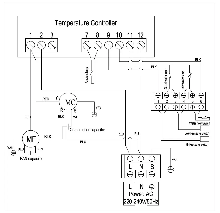
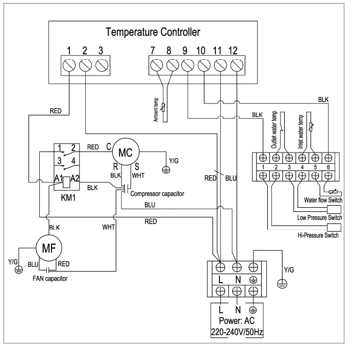
WIRING DIAGRAM
Please refer to the wiring diagram on the electric box.
A5/32, A7/32
A10/32, A13/32
SPECIFICATIONS
| Model | A5/32 | A7/32 | A10/32 | A13/32 | ||
| Air temperature: 15°C DB/12°C WB, water inlet/outlet temperature: 26°C/28°C | ||||||
| Heating capacity | kW | 3.30 | 4.80 | 7.10 | 9.13 | |
| Power input | kW | 0.71 | 1.06 | 1.48 | 1.96 | |
| COP | 4.65 | 4.53 | 4.80 | 4.66 | ||
| Air temperature: 26°C DB/23.5°C WB, water inlet/outlet temperature: 26°C/28°C | ||||||
| Heating capacity | kW | 4.50 | 6.60 | 9.60 | 12.50 | |
| Power input | kW | 0.95 | 1.39 | 1.85 | 2.06 | |
| COP | 4.74 | 4.75 | 5.19 | 6.06 | ||
| Power supply | 220 – 240V~, 1Ph, 50Hz | |||||
| Max power input | kW | 1.36 | 1.88 | 2.41 | 2.69 | |
| Max current | A | 6.31 | 8.52 | 10.73 | 12.23 | |
| Setting temperature range | 15°C – 40°C | |||||
| Running temperature range | 5°C – 43°C | |||||
| Refrigerant type/charged | R32/0.55kg | R32/0.65kg | R32/0.8kg | R32/1.1kg | ||
| Compressor | Brand | GMCC | Landa | |||
| Input | kW | 0.790 | 0.975 | 1.425 | 1.720 | |
| Air side heat-exchanger | Hydrophilic aluminum & Inner groove copper tube | |||||
| Fan motor | Fan type | Axial | ||||
| Fan size | mm | Φ427×139 | Φ427×139 | Φ522×140 | Φ522×140 | |
| Motor output | W | 32 | 32 | 60 | 60 | |
| Motor input | W | 80 | 80 | 150 | 150 | |
| Water side heat exchanger | Titanium heat-exchanger with PVC casing | |||||
| Advised water flow | m³/h | 1.9 | 2.5 | 4.5 | 6.2 | |
| Net dimension (L×D×H) | mm | 816×307×553 | 913×367×718 | |||
| Packing dimension (L×D×H) | mm | 885×360×670 | 1,010×450×851 | |||
| Net weight | kg | 37 | 40 | 47 | 54 | |
| Gross weight | kg | 41 | 46 | 53 | 60 | |
| Noise level (@10m) | dB(A) | 26 | 28 | 28 | 29 | |
| Water proof level | IPX4 | |||||
Notes:
The specification may be changed for product improvement, please refer to the nameplate of product.
MAINTENANCE
To protect the paintwork, avoid leaning or putting objects on the device. External heat pump parts can be wiped with a damp cloth and domestic cleaner. (Attention: Never use cleaning agents containing sand, soda, acid or chloride as these can damage the surfaces.)
To prevent faults due to sediments in the titanium heat exchanger of the heat pump, ensure that the heat exchanger cannot be contaminated (water treatment and filter system necessary).
In the even that operating malfunctions due to contamination still occur, the system should be cleaned as described below.
(Warning: the fins on the finned tube heat exchanger are sharp-edged — danger of being cut!)
Cleaning the pipe system in the heat exchanger
Contamination in the pipes and heat exchanger can reduce the performance of the heat pump’s titanium heat exchanger. If this is the case, the pipe system and heat exchanger must be cleaned by a technician.
Use only pressurized drinking water for cleaning.
Cleaning the air system
The finned heat exchanger, ventilator and condensate outflow should be cleaned of contaminants (leaves, twigs, etc.) before each new heating period. These types of contaminants can be manually removed using compressed air or by flushing with clean water.
It may be necessary to remove the device cover and air inlet grid first.
Attention: Before opening the device, ensure that all circuits are isolated from the power supply.
To prevent the evaporator and the condensate tray from being damaged, do not use hard or sharp objects for cleaning.
Under extreme weather conditions (e.g. snow drifts), ice may form on the air intake and exhaust air outlet grids. If this happens, the ice must be removed in the vicinity of the air intake and exhaust air outlet grids to ensure that the minimum air flow rate is maintained.
Winter Shutdown/Lay-up
If there is a chance of frost after the bathing-season has ended when the swimming pool heating is switched off and the external temperature is expected to drop below the operating limit, the water circuit of the heat pump should be completely drained. Otherwise, suitable constructional measures should be taken by the customer to protect the heat pump against damage from frost.
Attention: The warranty does not cover damage caused by inadequate lay-up measures during the winter.
TROUBLESHOOTING
This section provides useful information for diagnosing and correcting certain troubles which may occur. Before starting the troubleshooting procedure, carry out a thorough visual inspection of the unit and look for obvious defects such as loose connections or defective wiring.
Before contacting your local dealer, read this chapter carefully, it will save you time and money
![]() WHEN CARRYING OUT AN INSPECTION ON THE SWITCH BOX OF THE UNIT, ALWAYS MAKE SURE THAT THE MAIN SWITCH OF THE UNIT IS SWITCHED ‘OFF’.
WHEN CARRYING OUT AN INSPECTION ON THE SWITCH BOX OF THE UNIT, ALWAYS MAKE SURE THAT THE MAIN SWITCH OF THE UNIT IS SWITCHED ‘OFF’.
The guidelines below might help to solve your problem. If you cannot solve the problem, consult your installer/local dealer.
The heat pump will not run.
Please check whether:
- There is supply voltage (tripped fuse, power failure).
- The operating switch on the wired controller is switched on, and whether the correct set point temperature has been set.
The set temperature level cannot be reached.
Please check whether:
- The permissible operating conditions for the heat pump have been adhered to (air temperatures too high or too low).
- The air inlet or outlet area is blocked, restricted or very dirty.
- There are closed valves or stop-cocks in the water pipes.
If you cannot correct the fault yourself, please contact your after-sales service technician. Work on the heat pump may only be carried out by authorized and qualified after-sales service technicians.
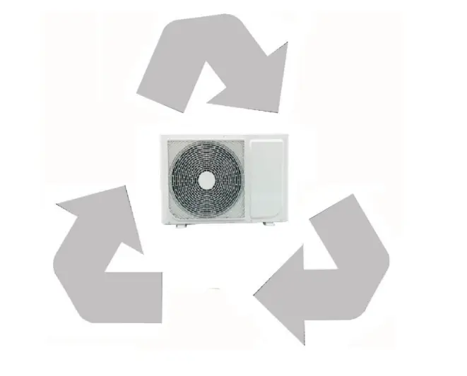
Recycling
ENVIRONMENTAL INFORMATION
This equipment contains fluorinated greenhouse gases covered by the Kyoto Protocol. It should only be serviced or dismantled by professional trained personnel.
This equipment contains R32 refrigerant in the amount as stated in the specification. Do not vent R32 into the atmosphere: R32, is a fluorinated greenhouse gas with a Global Warming Potential (GWP) = 675.
DISPOSAL REQUIREMENTS
Dismantling of the unit, treatment of the refrigerant, of oil and of other parts must be done in accordance with relevant local and national legislation.
 Your product is marked with this symbol. This means that electrical and electronic products shall not be mixed with unsorted household waste.
Do not try to dismantle the system yourself: the dismantling of the system, treatment of the refrigerant, of oil and other parts must be done by a qualified installer in accordance with relevant local and national legislation.
YOU HAVE THREE SOLUTIONS:
- Disposing of it at your local recycling centre
- Giving it to a social service organization for it to be repaired and put back into circulation.
- Returning it to the heat pump distributor against a new purchase.