![]() REV 2017-1
REV 2017-1
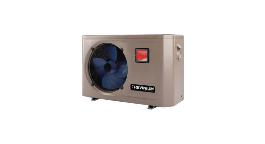
TREVINIUM by Hayward
SWIMMING POOL HEAT PUMP UNIT
Installation & Instruction Manual 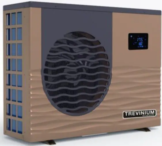 Model
Model
HP55TR HP7STR
USER INTERFACE
General presentation
The heat pump is equipped with a digital control panel with a touch screen, electronically connected and pre-set at the factory in heating mode.
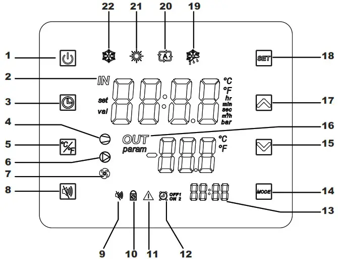
Legend
| 1 | 12 | ||
| 2 | 13 | ||
| 3 | 14 | ||
| 4 | 15 | ||
| 5 | 16 | ||
| 6 | 17 | ||
| 7 | 18 | ||
| 8 | 19 | ||
| 9 | 20 | ||
| 10 | 21 | ||
| 11 | 22 |
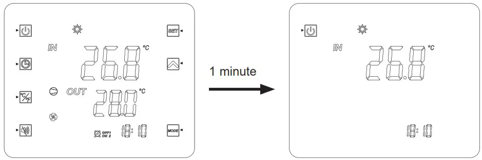
OFF Mode
When the heating pump is in sleep mode (OFF Mode) “OFF” is displayed on the command screen.
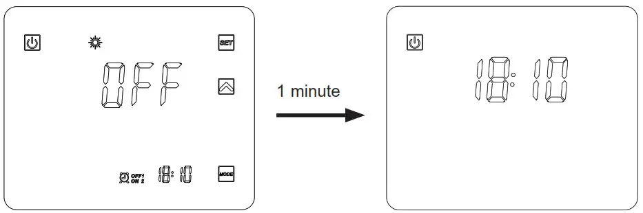
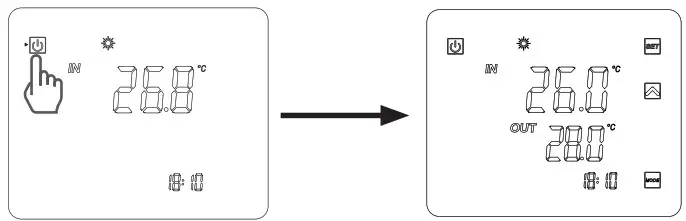
ON Mode
When the heating pump is running or regulating (ON Mode), the inlet and outlet water temperatures are displayed on the command screen.
At the end of a setting, press ![]() to validate.
to validate.
The settings will be automatically saved if no button is pressed during 20s.
Clock settings
If the display is in standby mode, press briefly on ![]() .
.
- Press
 to bring up the symbol
  .
. - Press to make the time display flash. Set the hour using the buttons

- Press then set the minutes with the buttons .
- Press to validate.
Timer function settings
Setting this function is necessary if you would like to run the heat pump for a shorter period than what is defined by the filtration clock. Therefore, you can program a deferred start and an anticipated stop or simply stop a certain timeframe from running (at night, for example).
It is possible to set 2 Start Timers (ON1 et ON2) and 2 Stop Timers (OFF1 et OFF2).
Timer 1 setting – Start
- Press for 2s, Timer ON1
 1 flashes (*).
 - Press to set the hours with the buttons .
- Press to set the minutes with the buttons .
- Press to validate.
Timer 1 setting – Stop
- Press for 2s, Timer ON1 1flashes (*).
Press once, Timer OFF1
  flashes.
 - Press to set the hours with the buttons.
- Press to set the minutes with the buttons.
- Press to validate.
(*) To access Timer ON2 ![]() 2directly, press
2directly, press ![]() for 2s, then press
for 2s, then press ![]() twice.
twice.
Timer 2 settings
After the Timer 1 settings, you will access directly the settings for Timer 2: ![]() 2 and
2 and ![]() 2.
2.
Proceed in the same manner as for Timer 1.
Nota: To access directly Timer ON2 ![]() 2, press
2, press ![]() for 2s, then press twice on
for 2s, then press twice on![]() .
.
Timers suppression (Start and Stop)
- Press for 2s, Timer ON1 1 flashes.(*)
- Press to make the time display flash.
- Press
 to suppress the Timer 1.
 - Press to validate.
- Press for 2s, the Timer 1 flashes.
Press once, the Timer  1 flashes.(*)
 - Press to make the time display flash.
- Press to suppress the Timer1.
(*) To access Timers 2 ![]() 2 or
2 or ![]() 2. , follow steps 1) or 4) then press twice
2. , follow steps 1) or 4) then press twice ![]() . Proceed in the same manner as above.
. Proceed in the same manner as above.
Operation mode selection: cooling, heating or automatic
In Mode “OFF” or “ON”
Press the button ![]() to change mode: cooling, heating or automatic.
to change mode: cooling, heating or automatic.
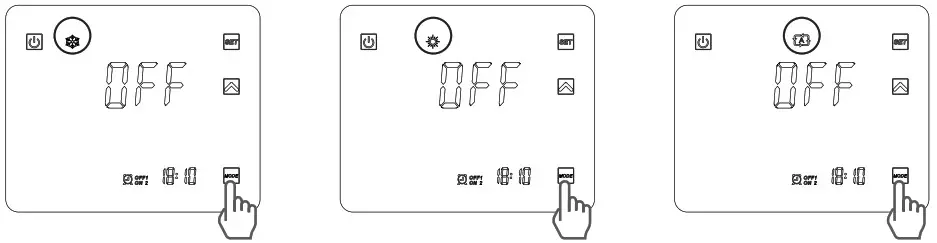
![]() If the heat pump is set in heating only or cooling only, changing mode is not possible.
If the heat pump is set in heating only or cooling only, changing mode is not possible.
Setting and visualisation of the set point (desired water temperature)
If the button ![]() is not visible on the screen, press
is not visible on the screen, press ![]() briefly. (While operating or stopped, simply press the button
briefly. (While operating or stopped, simply press the button ![]() to view the set point)
to view the set point)
In Mode “OFF” or Mode “ON”
Press the button ![]() to display the set point, then press
to display the set point, then press ![]() or
or ![]() to set the set point you wish.
to set the set point you wish.
The setting is made with a precision of 0.5 °C.
It is recommended to never exceed 30°C to avoid alteration of the liners.
Press the button ![]() for 5 s until it beeps and this symbol appears
for 5 s until it beeps and this symbol appears ![]() .
.
To unlock, press ![]() for 5 s until it beeps and this symbol disappears
for 5 s until it beeps and this symbol disappears ![]() .
.
6.3 Exploded View- HP55TR
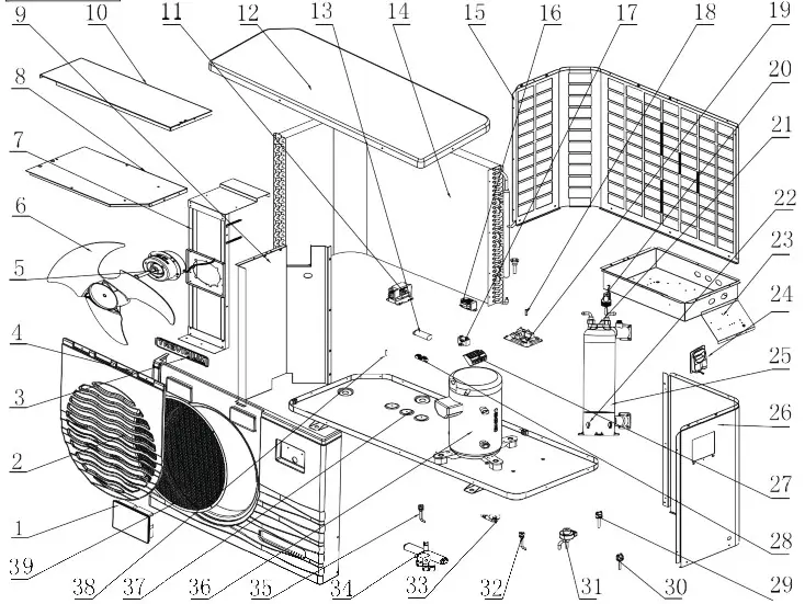
6.3 Spare Parts List -HP55TR
| No9 | Code | Part name | Part number |
| 1 | 95005-310261 | LED controller | HPX95005-310261 |
| 2 | 32012-210488 | Fan protection grille | HPX32012-210488 |
| 3 | 20000-230340 | Brand | HPX20000-230340 |
| 4 | 32012-220074 | Front panel | HPX32012-220074 |
| 5 | 20000-330124 | Motor | HPX20000-330124 |
| 6 | 3500-2701 | Fan blade | HPX3500-2701 |
| 7 | 32012-210418 | Motor support | HPX32012-210418 |
| 8 | 32012-210079 | Electrical box cover | HPX32012-210079 |
| 9 | 32012-210414 | Middle panel | HPX32012-210414 |
| 10 | 32012-210415 | Support panel | HPX32012-210415 |
| 11 | 20000-360103 | AC contactor | HPX20000-360103 |
| 12 | 32012-210489 | Top cover | HPX32012-210489 |
| 13 | 2000-3526 | Compressor capacitor | HPX2000-3526 |
| 14 | 32012-120102 | Evaporator | HPX32012-120102 |
| 15 | 32012-210600 | Left panel | HPX32012-210600 |
| 16 | 20000-370003 | Transformer | HPX20000-370003 |
| 17 | 2000-3501 | Fan motor capacitor | HPX2000-3501 |
| 18 | 2000-3242 | Coil temp. sensor | HPX2000-3242 |
| 19 | 95005-310145 | PCB board | HPX95005-310145 |
| 20 | 20000-360005 | Flow switch | HPX20000-360005 |
| 21 | 2000-3242 | Water inlet sensor | HPX2000-3242 |
| 22 | 2000-3242 | Water outlet sensor | HPX2000-3242 |
| 23 | 32012-210078 | Electrical box | HPX32012-210078 |
| 24 | 32009-220032 | Handle | HPX32009-220032 |
| 25 | 32012-120142 | PVC titanium condensor | HPX32012-120142 |
| 26 | 32012-210601 | Right panel | HPX32012-210601 |
| 27 | 2001-3907 | Terminalblock5connection | HPX2001-3907 |
| 28 | 2000-3909 | Terminalblock2connections | HPX2000-3909 |
| 29 | 20000-360157 | Pressure switch (0.3MPa/0.15MPa) | HPX20000-360157 |
| 30 | 2001-3605 | Pressure switch(3.2MPa/4.4MPa) | HPX2001-3605 |
| 31 | 20000-140451 | Electronic expansion valve | HPX20000-140451 |
| 32 | 20000-140153 | Needle valve | HPX20000-140153 |
| 33 | 3400-2203 | Drain connector | HPX3400-2203 |
| 34 | 2004-1437 | 4wayvalve | HPX2004-1437 |
| 35 | 20000-140153 | Needle valve | HPX20000-140153 |
| 36 | 20000-110267 | Compressor | HPX20000-110267 |
| 37 | 32012-210599 | Chassis | HPX32012-210599 |
| 38 | 2000-3242 | Ambient temp. Sensor | HPX2000-3242 |
| 39 | 32018-210143 | Embedded network | HPX32018-210143 |
6.3 Exploded view – HP75TR
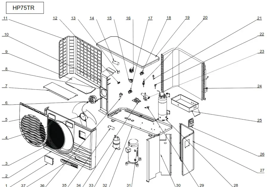
6.3 Spare parts list HP75TR
| No. | Part code | Part name | Part number |
| 1 | 95005-310261 | Glass controller | HPX95005-310261 |
| 2 | 32009-220076 | Front Plate | HPX32009-220076 |
| 3 | 32018-210143 | Fan protection net | HPX32018-210143 |
| 4 | 20000-270004 | Axial fan | HPX20000-270004 |
| 5 | 32009-210386 | Front panel | HPX32009-210386 |
| 6 | 20000-330134 | Fan motor | HPX20000-330134 |
| 7 | 32009-210500 | Supporting transom | HPX32009-210500 |
| 8 | 32018-210113-04 | Fan motor holder | HPX32018-210113-04 |
| 9 | 32009-210499 | Electrical box cover | HPX32009-210499 |
| 10 | 32009-210463 | Fan bracket | HPX32009-210463 |
| 11 | 32009-210391 | Left panel | HPX32009-210391 |
| 12 | 2000-3909 | Terminal-2 | HPX2000-3909 |
| 13 | 2000-3509 | Fan capacitor | HPX2000-3509 |
| 14 | 2000-3524 | Compressor capacitor | HPX2000-3524 |
| 15 | 20000-370003 | Transformer | HPX20000-370003 |
| 16 | 20000-360222 | Compressor contactor | HPX20000-360222 |
| 17 | 2001-3906 | Terminal-3 | HPX2001-3906 |
| 18 | 2001-3909 | Terminal-3 | HPX2001-3909 |
| 19 | 32018-210127 | Top panel | HPX32018-210127 |
| 20 | 20000-360005 | Water flow switch | HPX20000-360005 |
| 21 | 20000-360157 | Low pressure switch | HPX20000-360157 |
| 22 | 2001-3605 | High pressure switch | HPX2001-3605 |
| 23 | 2001-1491 | 4-way reverse valve | HPX2001-1491 |
| 24 | 32009-120062 | Heat exchanger | HPX32009-120062 |
| 25 | 32009-210498 | Electric box | HPX32009-210498 |
| 26 | 32009-220032 | Wiring box | HPX32009-220032 |
| 27 | 32009-210497 | Right panel | HPX32009-210497 |
| 28 | 32009-120073 | Titanium pipe heat exchanger | HPX32009-120073 |
| 29 | 3400-2203 | Drain connection | HPX3400-2203 |
| 30 | 32009-210460 | Middle panel | HPX32009-210460 |
| 31 | 20000-110142 | Compressor | HPX20000-110142 |
| 32 | 32009-210496 | Chassis | HPX32009-210496 |
| 33 | 3500-1401 | Gas-Liquid separator | HPX3500-1401 |
| 34 | 95005-310145 | Pc1001 PCB controller | HPX95005-310145 |
| 35 | 2000-3510 | Compressor capacitor | HPX2000-3510 |
| 36 | 20000-140237 | Electronic expansion valve | HPX20000-140237 |
| 37 | 20000-230340 | Brand | HPX20000-230340 |
![]()


