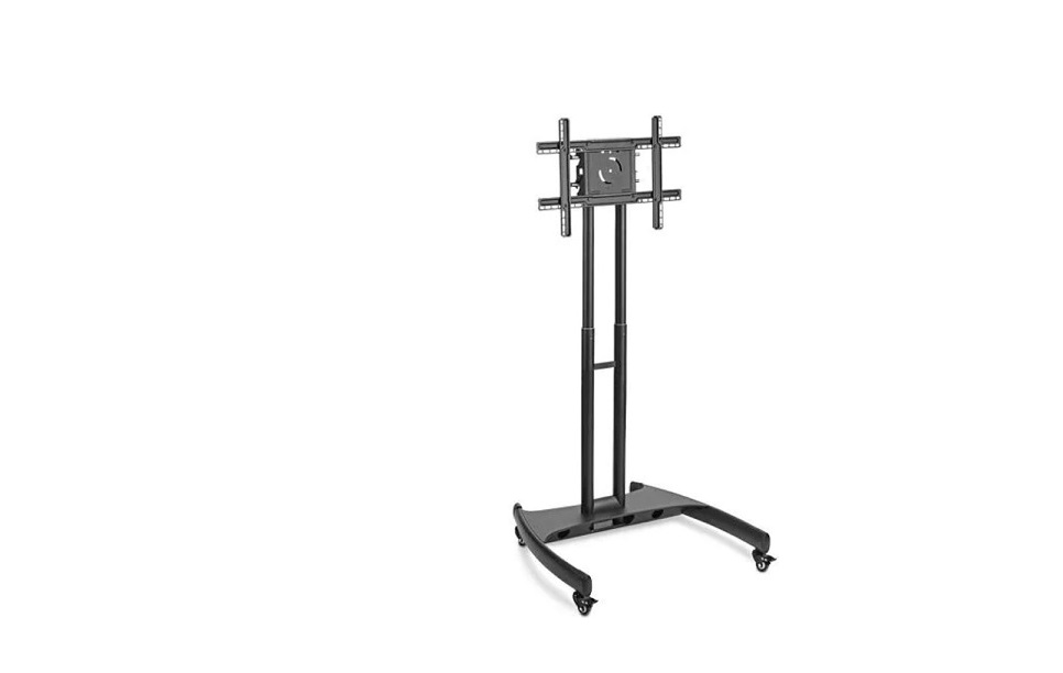
ULINE H-5487 Flat Screen Cart Installation Guide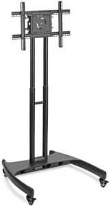
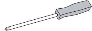
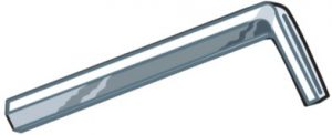
TOOLS NEEDED
- Phillips Screwdriver

- Allen Wrench

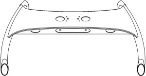
- Base x 1

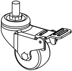
- Caster x 4

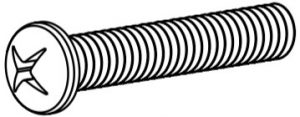
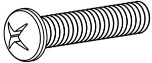
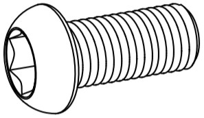
- Mounting Bolt A x 4 (M8 x 25mm)

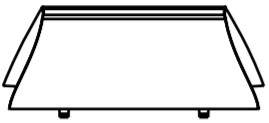
- Bolt Cover x 1

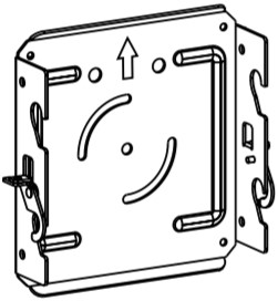
- Mounting Plate x 1

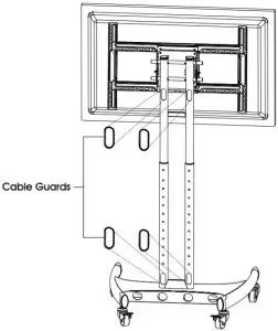
- Cable Guard x 4

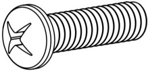
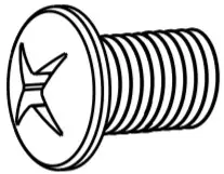
- Mounting Bolt B x 4 (M6 x 25mm)

- Mounting Bolt C x 4 (M5 x 25mm)

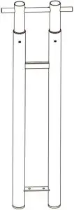
- Upright Assembly x 1

- Base Bolt x 4 (M8 x 20mm)

- Crossbar x 1

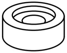
- Spacer x 4

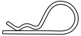
- Cotter Pin x 1

- Bar Bolt x 8 (M6 x 10mm)

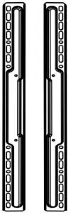
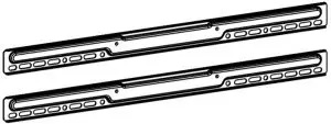
- Short Vertical Mounting Bar x 2

- Long Horizontal Mounting Bar x 2

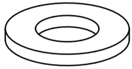
- Washer x 4

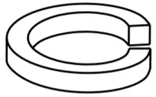
- Lock Washer x 4


SAFETY
![]() WARNING! Severe personal injury and property damage can result from improper installation.
WARNING! Severe personal injury and property damage can result from improper installation.
Read instructions carefully before beginning.
- Do not install or assemble if the product is damaged or hardware is missing.
- This product fits most 32-60″ flat panel displays; maximum weight for the display is 100 lbs. (45.5 kg).
- Do not use this product for anything other than what it was originally designed.
ASSEMBLY
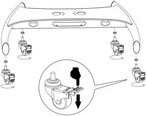
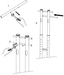
- Lock casters. Place lock washer over caster stem and screw into base. (See Figure 1)

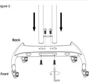
- Insert upright assembly into base with cable management holes facing back of unit. Fasten in place with four base bolts. (See Figure 2)

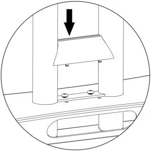
- Snap bolt cover into place. (See Figure 3)

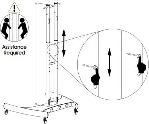
- . Adjust uprights to desired height using plunger buttons. (See Figure 4)

 NOTE: Never adjust height with the cables connected or flat screen mounted.
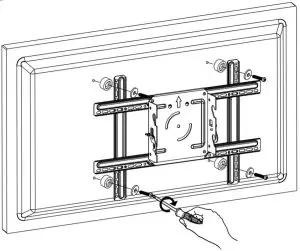
 - Unscrew pre-installed bolts from crossbar. Slide crossbar into position and screw bolts back into place. (See Figure 5)

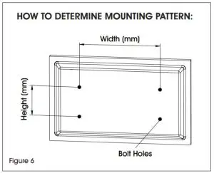
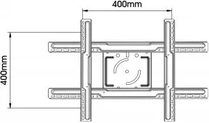
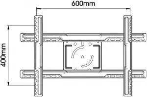
- Check your flat screen to determine the mounting pattern and mounting bolt size needed. Several common mounting patterns are shown here. (See Figures 6-7)


 NOTE: Test bolt size in flat screen to determine correct size.
Mounting Bolt A – Used on flat screens with larger 8mm bolt holes.
Mounting Bolt B – Used on flat screens with medium 6mm bolt holes.
Mounting Bolt C – Used on flat screens with smaller 5mm bolt holes. NOTE: If flat screen is already mounted on a pedestal, remove pedestal prior to mounting. - Attach mount assembly to flat screen. NOTE: Spacers should be used between mounting bars and flat screen to avoid damage. (See Figure 8)

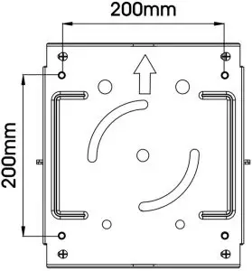
FOR 200mm x 200mm MOUNTING PATTERNS:
If using a 200mm x 200mm mounting pattern, attach mounting plate directly to flat screen using mounting bolts, washers and spacers. (See Figure 9)
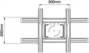
FOR ALL OTHER MOUNTING PATTERNS:
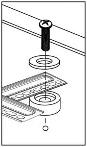
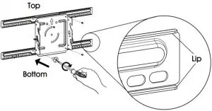
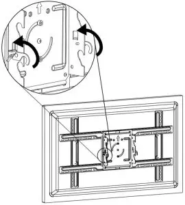
For all larger mounting patterns, attach long horizontal mounting bars to mounting plate using four bar bolts. (See Figure 10) NOTE: To correctly position horizontal mounting bars, make sure oval mounting holes are on the bottom and the lips face the mounting plate. NOTE: To correctly position vertical mounting bars make sure oval mounting holes are centered at the width of your mounting pattern and the lips face the mounting plate. NOTE: Before continuing to step 8, make sure
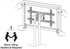
casters are in the locked position. (See Figure 13) - Lift lock hooks on mounting plate. (See Figure 14)

- Lift flat screen and hook mounting plate onto crossbars. (See Figure 15)

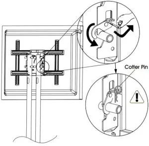
- Secure flat screen by engaging lock hook and fastening with cotter pin. (See Figure 16)

- Snap cable guards into place. (See Figure 17)


 1-800-295-5510
uline.com


