![]() 011172
011172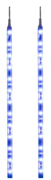 LED STRIP Operating instructions
(Translation of the original instructions)
Important! Read the user instructions carefully before use. Save them for future reference. Jula reserves the right to make changes. For the latest version of operating instructions, see www.jula.com
Care for the environment!
 Recycle discarded products in accordance with local regulations.
SAFETY INSTRUCTIONS
WARNING!
- Do not use the product if it can in any way put the road safety of the vehicle at risk. Do not point the light at the driver or out from the vehicle. The buyer is responsible for installing and using the product as it is intended to be used and in accordance with the rules and regulations, and laws, concerning vehicle lights.
- The manufacturer cannot accept liability for any damage resulting from illegal or unintended use.
| Read the instructions. | |
 | Approved in accordance with the relevant directives. |
| Recycle discarded products in accordance with local regulations. |
TECHNICAL DATA
| output | 18×0.2 W |
| voltage | 12 V |
| Cable length | 1 m |
| Size | L 30.5 cm |
| color of LED strip | Blue |
DESCRIPTION
- LED strips 2x.
- Bright, surface-mounted (SMD) LEDs.
- Can be cut to the required length.
- Bendable and flexible silicone rubber core.
- Self-adhesive — 3M foam rubber tape on the back.
- Simple mounting — pull off the protective film and press in place.
- Suitable for both internal and external use.
MOUNTING
- Carefully clean the surface on which the product is to be mounted from oil residue and other impurities.
- Pull off the protective film from the back of the product and apply the 3M foam rubber tape on the mounting surface. Press on firmly to fasten the tape. The product bends to the shape of the Surface.
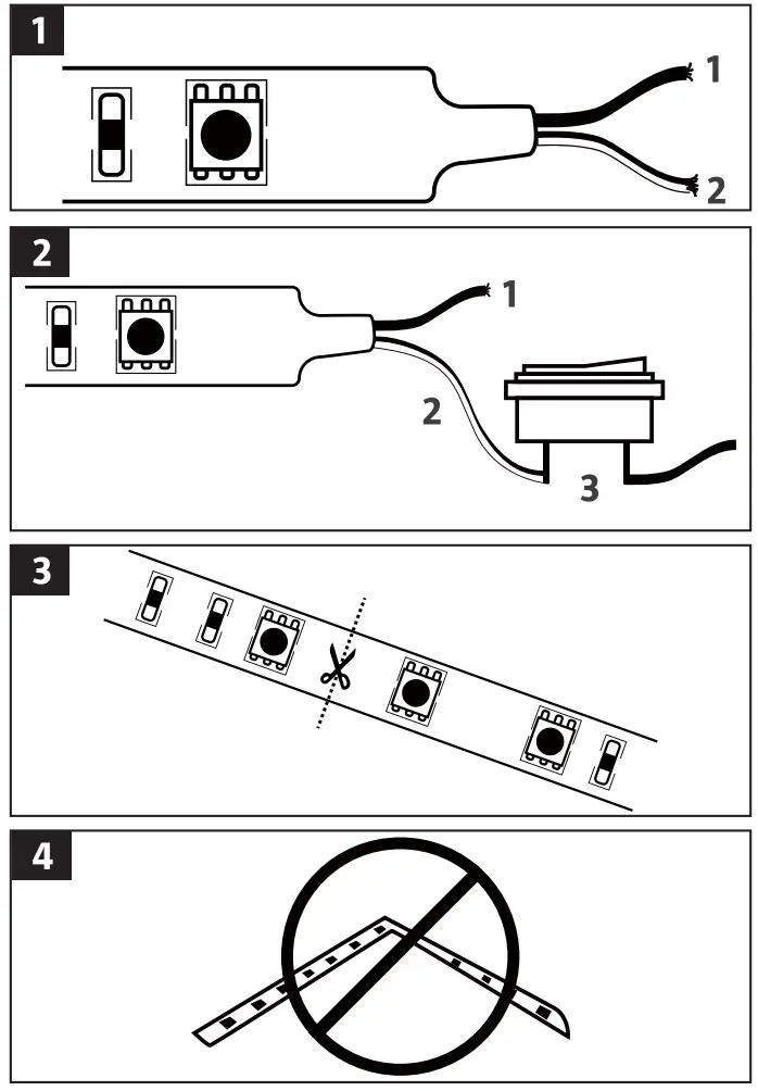
- Connect the black wire to the chassis (earth) and the black/white wire to +12V on the vehicle, either by connecting to an ignition switch circuit (fig. 1) or a separate switch (fig. 2). FIG. 1
- Black wire — chassis (earth).
- Black/white wire — ignition switch circuit.
FIG. 2
1. Black wire — chassis (earth)
2. Black/white wire
3. Constant 12 V (not ignition switch)
4. Cut to the right length: the product must only be cut at the points marked with a scissor symbol.FIG. 3
NOTE:
- The product must not be folded and cannot be mounted in sharp corners.
FIG. 4 - Do not connect the product directly to the vehicle battery.


