Hamron 016031 LED Light Bar Instruction Manual

 OPERATING INSTRUCTIONS
 OPERATING INSTRUCTIONS
Important! Read the user instructions carefully before use. Save them for future reference. (Translation of the original instructions)
SAFETY INSTRUCTIONS
- Read these instructions carefully before installation and save them for future reference.
- Always comply with the applicable laws and regulations for the installation and use of auxiliary headlights.
SYMBOLS
| SYMBOLS | |
 | Read the instructions. |
|
| Approved in accordance with the relevant directives. |
 | Recycle discarded product in accordance with local regulations. |

TECHNICAL DATA
| Rated voltage | 9 – 36 VDC |
| Light source | 36 x 5 W LED |
| Output | 180 W |
| Luminous flux | 16200 lm |
| Colour temperature | 6000 K |
| Range | 1 lux at 472 m |
| Range | 0.25 lux at 927 m |
| Protection rating | IP68 |
| Cord length | 50 cm |
| E-approved | Yes |
| ETM* | Yes |
* Electronic thermal management
DESCRIPTION
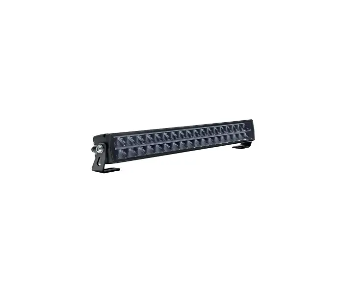
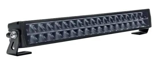
Powerful extra lighting that makes driving safer and less tiring. Hamron’s powerful light bar has double rows of ultrabright LED light sources.
This produces a wider and more powerful beam. There are a total of 36 x 5 W LED light sources that deliver 16200 theoretical lumen and 13770 actual lumen. The beam is a so-called Combo beam, which means that the light bar produces a beam a long way
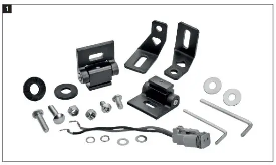
ahead on the road, while diffuse reflectors on the sides create a wide and uniform beam to provide light on the sides of the road. LED light sources have electronic thermal monitoring (ETM), which retains the intensity of the diodes and avoids discolouring if the heat becomes excessive. Adapted for fixed installation and mounted on the supplied side fasteners made of stainless steel. Installation accessories and DT connector included FIG. 1
ETM
Thanks to Electronic Thermal Management (ETM) the intensity of the diodes is maintained and discolouring is avoided if the heat becomes excessive.
INSTALLATION
- Disconnect the negative/chassis earth cable from the battery before connecting the product, to avoid damage from shortcircuiting during the installation.
- Follow as far as possible the existing cable routing for installation of new cables. Carefully fasten the cable and any excess length with cable ties, insulating tape or the equivalent. Cable grommets through
the firewall should be at a safe distance from moving parts. - Drill screw holes with a diameter of 8.5 mm in the surface where the product is to be installed.
- The product can be mounted with side (1) or bottom (2) fasteners. Put the screws
in the holes, put on the lock washers and tighten the nuts. FIG. 2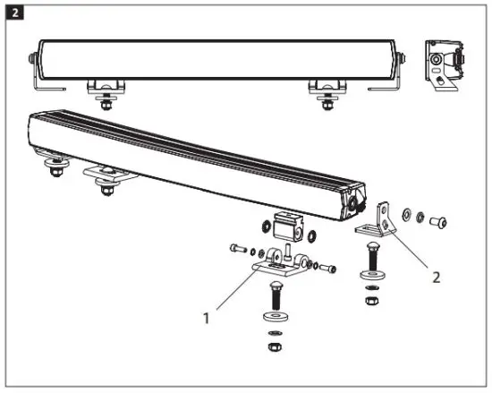
Cable colour coding
The DT connector’s red wire is (+) and the black wire is (–).
WARNING!
- The product must only be used within its rated voltage range, 9 to 36 VDC.
- The light source gets hot when the product is switched on. Allow the light source to cool for at least 30 minutes before touching or handling it.
- Make sure there is a free flow of air through the cooling fins on the light source and keep the fins clean.


