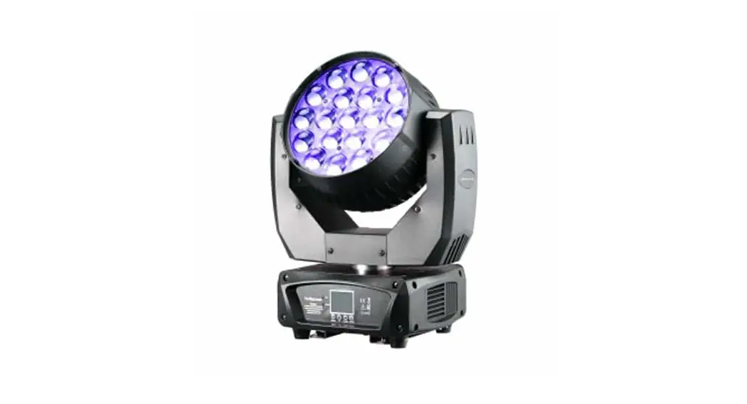
LED MOVING WASH 7 RGBW ZOOM PLUS
User manual
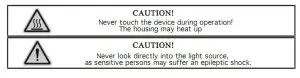
CAUTION!
Keep this device away from rain and moisture!
Unplug mains lead before opening the housing!
FOR YOUR OWN SAFETY, PLEASE READ THIS USER MANUAL CAREFULLY
BEFORE YOUR INITIAL START-UP!
Introduction
Thank you for having chosen the item. You acquired a versatile, powerful and intelligent lighting effect. Unpack your unit and make sure that there are no damages caused by transportation. Should there be any, please consult your local dealer and do not take the device into operation.
Features
shutter/dimmer unit allowing very smooth dimming and strobe effect 1-30 flashes per sec. · LCD display · Readout fixture, receiving DMX values· remote reset function · 14 DMX-channels· Pan-movement range 530° · Tilt-movement range 280° · DMX-control via every standard DMX-controller
Operating determinations
This device is a moving-head spot for creating decorative effects. This product is only allowed to be operated with an alternating current of 100-240V,50/60 Hz, and was designed for indoor use only. This device is designed for professional use, e.g. on stages, in discotheques, theatres, etc. Lighting effects are not designed for permanent operation. Consistent operation breaks will ensure that the device will serve you for a long time without defects. Do not shake the device. Avoid brute force when installing or operating the device. The minimum distance between light output and the illuminated surface must be more than 1 meter. Always fix the fixture with an appropriate safety rope. Fix the safety rope at the correct holes only. Only operate the fixture after having checked that the housing is firmly closed and all screws are tightly fastened. The maximum ambient temperature ta must never be exceeded.
DANGER OF FIRE!
When installing the device, make sure there is no highly-inflammable materials within a distance of min. 0.5 m.
CAUTION!
Use 1 appropriate clamp to rig the fixture on the truss.
Follow the instructions mentioned at the bottom of the base.
Use 2 appropriate clamps to rig the fixture on the truss. Follow the instructions mentioned at the bottom of the base. Make sure that the device is fixed properly! Ensure that the structure (truss) to which you are attaching the fixtures is secure. Clamps must be locked with both 1/4 turns and the 1/4 turns lock in position when turned fully clockwise. Always use two clamps to mount the fixture. Always secure safety wire before suspending the fixture. Use the m10 screws to fix the clamps on the fixing holders on the bottom of the device and then screw the hanging screw into the bottom base and put it on a safety wire.
DMX-512 connection / connection between fixtures
The wires must not come into contact with each other, otherwise, the fixtures will not work at all, or will not work properly.
Only use a stereo shielded cable and 3-pin XLR-plugs and connectors in order to connect the controller with the fixture or one fixture with another. Connect the DMX output of the first fixture in the DMX chain with the DMX input of the next fixture. Always connect one output with the input of the next fixture until all fixtures are connected. At the last fixture, the DMX-cable has to be terminated with a terminator. Solder a 120 resistor between Signal () and Signal (+) into a 3-pin XLR-plug and plug it in the DMX-output of the last fixture.
1. DMX 512 protocol
Addressing
The LCD DISPLAY on the bottom side of the base allows you to assign the DMX fixture address, which is defined as the first channel from which the item will respond to the controller. If you set, for example, the address to channel 7, the item will use channels 7 to 14 for control. Please, be sure that you don’t have any overlapping channels in order to control each item correctly and independently from any other fixture on the DMX data link. If two, three or more items are addressed similarly, they will work similarly. At DMX mode you can choose the address from 1 to 512. After you connect the item to the mains, the item starts running. When the item finishes resetting, OO1 will flash in the lcd display and then set the desired DMX address by pressing the UP or DOWN buttons. DMX Controlling: After having addressed all items, you may now start operating these via your lighting controller. After switching on, the item will automatically detect whether DMX 512 data is received or not.
The function of the control channels
DMX MODE
14-channel mode
Channel 1 – pan movement (Pan)
Channel 2 – pan fine 16 bit
Channel 3 – Vertical movement (Tilt)
Channel 4 – tilt fine 16 bit
Channel 5 – pan, tilt speed adjustment from fast to slow
Channel 6 -reset
| 0-9 | not occupied |
| 10-14 | reset |
| 15-255 | not occupied |
Channel 7 – master dimmer from 0-100%
Channel 8 – strobe
| 0-19 | off |
| 20-24 | open |
| 25-64 | strobe |
| 65-69 | open |
| 70-84 | opening pulse |
| 85-89 | open |
| 90-104 | closing pulse |
| 105-109 | open |
| 110-124 | random strobe |
| 125-129 | open |
| 130-144 | random opening pulse |
| 145-149 | open |
| 150-164 | random closing pulse |
| 165-169 | open |
| 170-184 | burst pulse |
| 185-189 | open |
| 190-204 | random burst pulse |
| 205-209 | open |
| 210-224 | sine wave(special strobe effect) |
| 225-229 | open |
| 230-244 | burst |
| 245-255 | open |
Channel 9 -red from 0-100%
Channel 10 -green from 0-100%
Channel 11 -blue from 0-100%
Channel 12 -white from 0-100%
Channel 13 -color macros,color-changing, random color fades
| 0-9 | off |
| 10-174 | 33 colors |
| 175-179 | off |
| 180-201 | color changing from fast to slow |
| 202-207 | stop |
| 208-229 | color fade from slow to fast |
| 230-234 | off |
| 235-239 | the random color I(fast) |
| 240-244 | random color II(middle) |
| 245-249 | random color III(slow) |
| 250-255 | off |
Channel 14 -zooming from 8° to 60°
2. auto:
Press the button menu, scroll through by the buttons up or down till fixture test appears in the display, push the button enter, select and confirm the autotest by the buttons up, down and enter, then the fixture runs preset shows.
3. Control Board
The Control Board offers several features: you can simply set the starting address, reset. The main menu is accessed by pressing the MENU and browsing through the menu by pressing the Up, or Down button. Press the Enter button in order to select the desired menu. You can change the selection by pressing the Up or Down button. Confirm every selection by pressing the Enter button. You can leave every mode by pressing the menu. The functions provided are described in the following sections:
| DMX FUNCTIONS | DMX Address | 001-512 |
| VIEW DMX Value | 1.Pan 000-255 | |
| 2.Pan Fine 000-255 | ||
| 3.Tilt 000-255 | ||
| 4.Tilt Fine 000-255 | ||
| 5.P/T Speed 000-255 | ||
| 6.SPECIAL FUNCTIONS 000-255 | ||
| 7.Dimmer 000-255 | ||
| 8.Shutter 000-255 | ||
| 9.Red 1 000-255 | ||
| 10.Green 1 000-255 | ||
| 11.Blue 1 000-255 | ||
| 12.White 1 000-255 | ||
| 13.Color 1 000-255 | ||
| 14.Zoom 000-255 | ||
| FIXTURE SETTING | Pan Inverse | Yes |
| No | ||
| Tilt Inverse | Yes | |
| No | ||
| PIT Feedback | Yes | |
| No | ||
| Black P/T Moving | Yes | |
| No |
| #VALUE! | White Balance | Rod:125-255 |
| Green:125-255 | ||
| Blue:125-255 | ||
| DISPLAY SETTING | Display Inverse | Yes |
| No | ||
| Blacklight AUTO OFF | Yes | |
| No | ||
| Blacklight INTENSITY | 1–10 | |
| Temperature Unit | centigrade | |
| fahrenheit | ||
| Display WARNING | Yes | |
| No | ||
| FIXTURE TEST | AUTO TEST | |
| MANUAL TEST | 1.Pan 000-255 | |
| 2.Pan Fino 000-255 | ||
| 3.Tilt 000-255 | ||
| 4.Tilt Fine 000-255 | ||
| 5.PIT Speed 000-255 | ||
| 6.SPECIAL FUNCTIONS 000-255 | ||
| 7.Dimmer 000-255 | ||
| 8.Shutter 000-255 | ||
| 9.Rod 1 000-255 | ||
| 10.Green 1 000-255 | ||
| 11.Blue 1 000-255 | ||
| 12.White 1 000-255 | ||
| 13.Color 1 000-255 | ||
| 14.Zoom 000-255 | ||
| FIXTURE INFORMATION | FIXTURE USE TIME | EXIT |
| RESET TIME | ||
| LAMP ON TIME | EXIT | |
| RESET TIME | ||
| FIRMWARE VERSION | CPU-A | |
| RESET FUNCTIONS | PAN/TILT | |
| ZOOM | ||
| ALL | ||
| SPECIAL functions | FIXTURE MAINTENANCE | INTERVAL 300H,EXIT/RESET TIME |
| REMAIN TIME 291H..EXIT/RESET TIME | ||
| FACTORY SETTING | NO | |
| YES |
Replacing the fuse
If the light burns out, the fine-wire fuse of the device might fuse, too. Only replace the fuse by a fuse of the same type and rating.
Before replacing the fuse, unplug the mains lead.
Procedure:
Step 1: Unscrew the fuse holder on the rear panel with a fitting screwdriver from the housing (anti-clockwise).
Step 2: Remove the old fuse from the fuse holder.
Step 3: Install the new fuse in the fuse holder.
Step 4: Replace the fuse holder in the housing and fix it.
Should you need any spare parts, please use genuine parts. If the power supply cable of this device becomes damaged, it has to be replaced by a special power supply cable available at your dealer. Should you have further questions, please contact your dealer.
TECHNICAL SPECIFICATIONS
Power supply: 100-240 V AC, 50/60 Hz ~
Power consumption: max. 320W
A number of LEDs: 7* high MCD 4 in 1 OSTAR RGBW LEDs, total max. 280W 8°-60° zooming
DMX-512-connection: 3-pin XLR or 5-pin XLR
DMX channel: 14
Pan/tilt auto repositioning
16 scannings fine bit
Movement: Pan:X axis 530 degrees, Y-axis 280 degrees
Flash-rate: 0-30Hz
Dimensions: 325*215*385mm
Weight (net):8.50kgs Maximum ambient temperature ta 40° C
Please note: All information is subject to change without prior notice.


