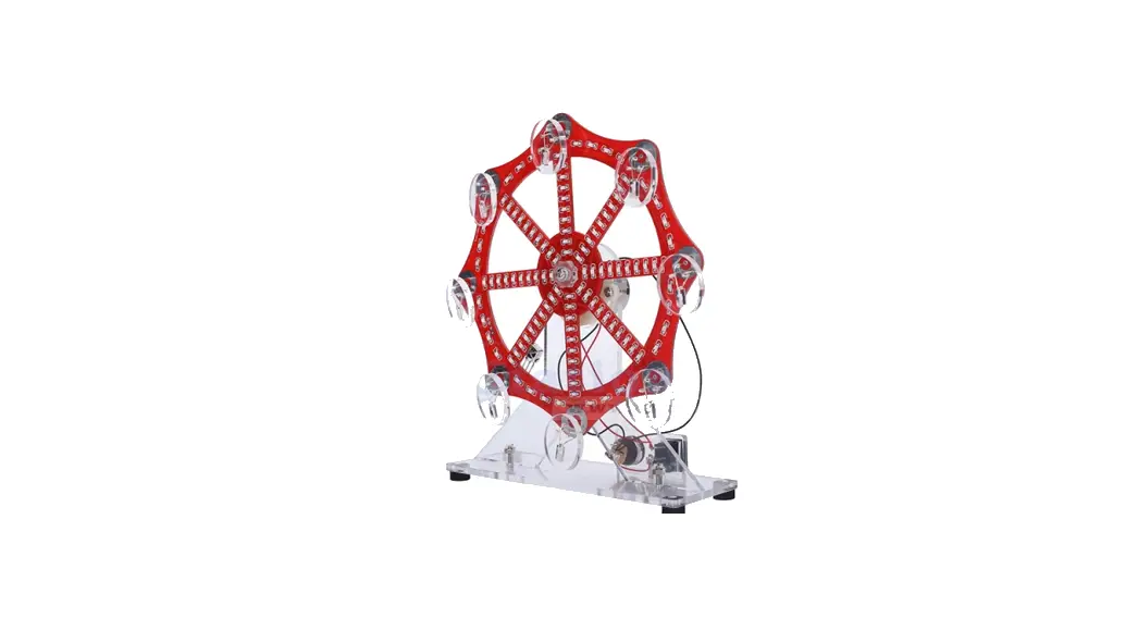
![]() LED Electronic Ferris Wheel DIY Kit
LED Electronic Ferris Wheel DIY Kit
Owner’s Manual
Introduction:
It is a Electronic Ferris Wheel DIY Kit with Red/Blue/Green/Yellow LED flashing in 10 animation mode which can be switch by remote control. It can simulate the working state of the Ferris wheel very realistically. As the Ferris wheel rotates, the LED will flash automatically.The user can also adjust the speed of the LED blinking.
It is a very interesting DIY electronic product which enables users to understand the circuit more clearly and learn welding skills.
Feature
- LED flashes automatically
- 10 animation mode
- Adjustable LED blinking speed in level 1~10
- Red/Blue/Green/Yellow LED flashing
- Perfect simple circuit
- DIY hand soldering
Parameter
- Product Name:Electronic Ferris Wheel DIY Kit
- Work Voltage:DC 4.5V-5.5V
- Work Temperature:-20℃~85℃
- Work Humidity:5%~85%RH
- Size(Installed):150*150*170mm
Use Steps
- Connect work voltage DC4.5V-5.5V from DC-005 power socket by USB wire.
- Press switch to turn ON power and the starts rotate and the LED flashing.
- Press again to turn OFF.
Component Listing
| NO. | Component Name | PCB Marker | Parameter | QTY |
| 1 | STC15W204S | U1 | SOP-16 | 1 |
| 2 | 0805 SMD Capacitor | C1 | 1 | |
| 3 | 0805 SMD Resistor | R1-R16 | 1Kohm | 16 |
| 4 | 0805 Red LED | SMD | 28 | |
| 5 | 0805 Blue LED | SMD | 28 | |
| 6 | 0805 Green LED | SMD | 28 | |
| 7 | 0805 Yellow LED | SMD | 28 | |
| 8 | Infrared Receiver | HX1 | 1 | |
| 9 | DC-005 Power Socket | 1 | ||
| 10 | Power Switch | 1 | ||
| 11 | 3mm Red LED | DIP | 2 | |
| 12 | 3mm Blue LED | DIP | 2 | |
| 13 | 3mm Green LED | DIP | 2 | |
| 14 | 3mm Yellow LED | DIP | 2 | |
| 15 | Spring | 2 | ||
| 16 | DC Motor | 1 | ||
| 17 | USB Power Wire | 100cm | 1 | |
| 18 | Sponge Pad | Black | 4 | |
| 19 | 15cm Wire | Red/Black | 2 | |
| 20 | 10cm Wire | Red | 1 | |
| 21 | Remote Control | 1 | ||
| 22 | M3+15mm Screw | 2 | ||
| 23 | M3+10mm Screw | 5 | ||
| 24 | M3 Nut | 7 | ||
| 25 | M3 Pad | 4 | ||
| 26 | PCB | 150*150*1.6mm | 1 | |
| 27 | Acrylic Bottom Plate | 1 | ||
| 28 | Acrylic Type-Y Bracket | 1 | ||
| 29 | Acrylic Switch Bracket | 1 | ||
| 30 | Acrylic Spring Fix Bracket | 1 |
Application
- Training welding skills
- Student school
- DIY production
- Project Design
- Electronic competition
- Gift giving
- Crafts collection
- Home decoration
- Souvenir collection
- Graduation design
- Holiday gifts
Installation Tips
- User needs to prepare the welding tool at first.
- Please be patient until the installation is complete.
- The package is DIY kit.It need finish install by user.
- The soldering iron can’t touch the components for a long time(3s), otherwise damage components.
- Pay attention to the positive and negative of the components.
- Strictly prohibit short circuit.
- User must install the LED according to the specified rules.Otherwise some LED will not light.
- Install complex components preferentially.
- Make sure all components are in right direction and right place.
- Check that all of the LED can be illuminated.
- It is strongly recommended to read the installation manual before starting installation!!!
- Please wear anti-static gloves or anti-static wristbands when installing electronic components.
Installation Steps(Please be patient install!!!):
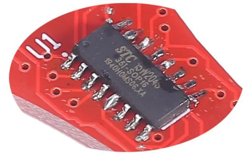
- Step 1: Install 1pcs SOP-16 STC15W204S at U1. Tips:
1.1>.Confirm the installation direction: There is a white dot on PCB and there is a mark(dot) on IC.
These two marks are corresponding to each other and are used to specify the installation direction.
1.2>.Place tin on one pad.
1.3>.Hold the chip with tweezers and melt the solder just now with a soldering iron at the same time.
1.4>.After aligning each pad and pin, use tweezers to place the IC on PCB.
1.5>.Remove soldering iron and hold IC by tweezers for about 5 second to waiting for fix pin.
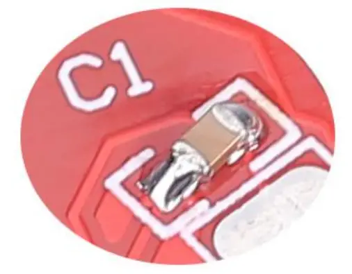
1.6>.Fix other pins and pads. - Step 2: Install 1pcs 0805 SMD Capacitor at C1. Tips:
2.1>.Place tin on one pad.
2.2>.Hold the capacitor with tweezers and melt the solder just now with a soldering iron at the same time.
2.3>.After aligning each pad and pin, use tweezers to place the capacitor on PCB.
2.4>.Remove soldering iron and hold capacitor by tweezers for about 5 second to waiting for fix pin.
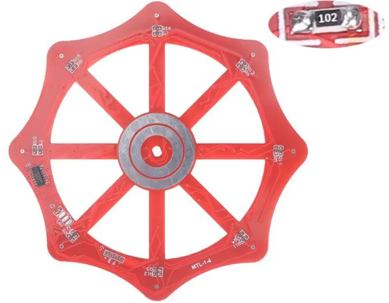
2.5>.Fix another pin and pad. - Step 3: Install 16pcs 1Kohm 0805 SMD Resistor at R1-R15.
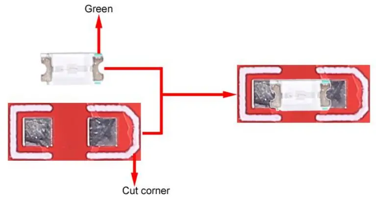
- Step 4: Identify the positive and negative poles of the LED.
4.1>.LED front: It is the negative pole where there is a greed mark.
4.2>.PCB mark: It is the negative pole where silk screen has cut corner. - Step 5: Install 28pcs 0805 Red LED.Pay attention to the installation direction and installation position.
- Step 6: Install 28pcs 0805 Blue LED.Pay attention to the installation direction and installation position.
- Step 7: Install 28pcs 0805 Green LED.Pay attention to the installation direction and installation position.
- Step 8: Install 28pcs 0805 Yellow LED.Pay attention to the installation direction and installation position.
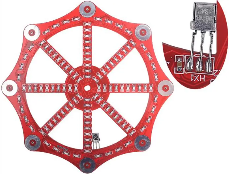
- Step 9: Install 1pcs Infrared Receiver at HX1. Pay attention to the installation direction.
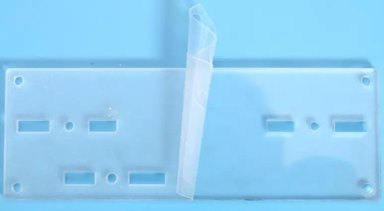
- Step 10: Tear off the acrylic surface protective film.
- Step 11: Fix 1pcs Acrylic Type-Y Bracket on Acrylic Bottom Plate by 2pcs M3+10mm Screw and 2pcs M3 Nuts.
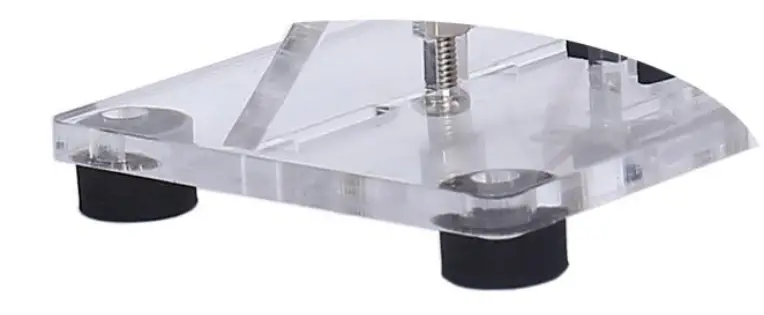
- Step 12: Fix 2pcs M3+15mm Screw and 2pcs M3 Nuts and 4pcs M3 Pads on Acrylic Spring Fix Bracket.(Tips: Pads are use to connect wire and screw for Spring)
- Step 13: Use the pads to clamp the red and black wires separately. Note that the red wire is connected to the pad near the middle of the acrylic.
- Step 14: Fix DC motor, Type-Y Bracket and Spring Fix Bracket by 2pcs M3+10mm Screw and 2pcs M3 Nuts. Pay attention to the installation order.
- Step 15: Place 2pcs Spring on 2pcs M3+15mm Screws.
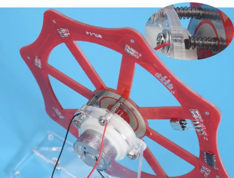
- Step 16: Place PCB on motor shaft.Take care to adjust the position of the springs so that they touch the ring pad on PCB.
- Step 17: Fix PCB on motor shaft by 1pcs Acrylic PCB Fix Bracket, 1pcs M3 Pad, 1pcs M3 Nut.
- Step 18: Install 1pcs DC-005 Power Socket on Acrylic Switch Bracket and fix by comes with screw.
- Step 19: Install 1pcs Power Switch on Acrylic Switch Bracket.
- Step 20: Connect positive pole from DC-005 Power Socket and Power Switch by 10cm red Wire. Take care to select the correct pins.
- Step 21: Connect red wire form motor and pad to switch. Connect black wire form motor and pad to DC-005 Power Socket.
- Step 22: Fix Acrylic Switch Bracket 1pcs M3+10mm Screw and 1pcs M3 Nuts.
- Step 23: Handling the LED pins. The short pins are slightly bent, the long pins are bent.
- Step 24: The short pin insert the largest hole and the long pin insert the top smaller hole.
- Step 25: Bend the LED to fit the LED into the largest hole.
- Step 26: Bend the left pin so that it coincides with the small hole on the left and bending.
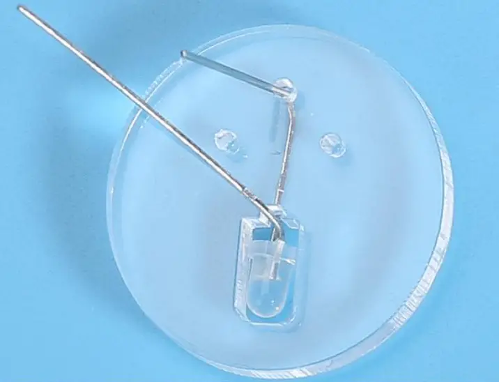
- Step 27: Bend the left pin three times with pliers to make the shape shown in the picture.
- Step 28: Insert pin to the last hole.
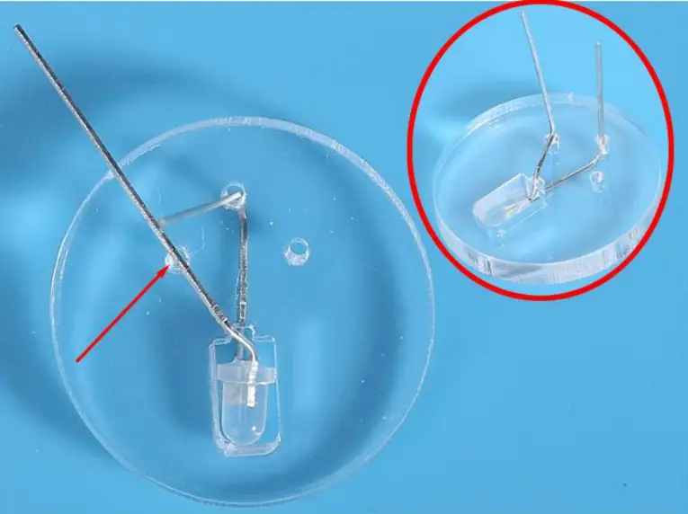
- Step 29: Insert the other pin of the LED into the PCB. Bend the pin slightly on the back of the PCB, bend the pin slightly to keep it from falling off. Note: It cannot be fixed, otherwise it cannot be rotated.
- Step 30: In the same way, install other LED.
- Step 31:Finally install 4pcs black pads on Acrylic Bottom Plate.
Install shown steps:
Step 1: Install 1pcs SOP-16 STC15W204S at U1. Tips:
- Confirm the installation direction: There is a white dot on PCB and there is a mark(dot) on IC. These two marks are corresponding to each other and are used to specify the installation direction.
- Place tin on one pad.
- Hold the chip with tweezers and melt the solder just now with a soldering iron at the same time.
- After aligning each pad and pin. use tweezers to place the IC on PCB. 5>.Remove soldering iron and hold IC by tweezers for about 5 second to waiting for fix pin.
- Fix other pins and pads.

Step 2: Install 1pcs 0805 SMD Capacitor at Cl. Tips:
- Place tin on one pad.
- Hold the capacitor with tweezers and melt the solder just now with a soldering iron at the same time.
- After aligning each pad and pin. use tweezers to place the capacitor on PCB. 4>.Remove soldering iron and hold capacitor by tweezers for about 5 second to waiting for fix pin.
- Fix another pin and pad.

Step 3: Install 16pcs 1Kohm 0805 SMD Resistor at R1-R15.
Step 4: Identify the positive and negative poles of the LED.
- LED front: It is the negative pole where there is a greed mark.
- PCB mark: It is the negative pole where silk screen has cut corner.
Step 5: Install 28pcs 0805 Red LED. Pay attention to the installation direction and installation position. 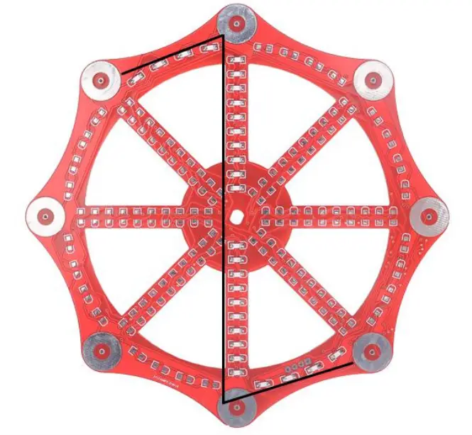
Step 6: Install 28pcs 0805 Blue LED. Pay attention to the installation direction and installation position. 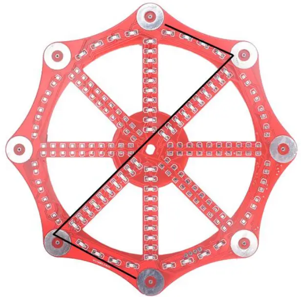
Step 7: Install 28pcs 0805 Green LED. Pay attention to the installation direction and installation position. 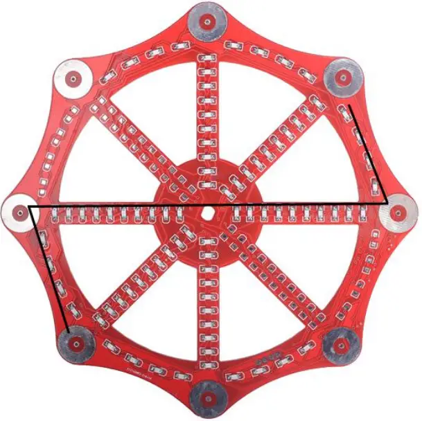
Step 8: Install 28pcs 0805 Yellow LED. Pay attention to the installation direction and installation position. 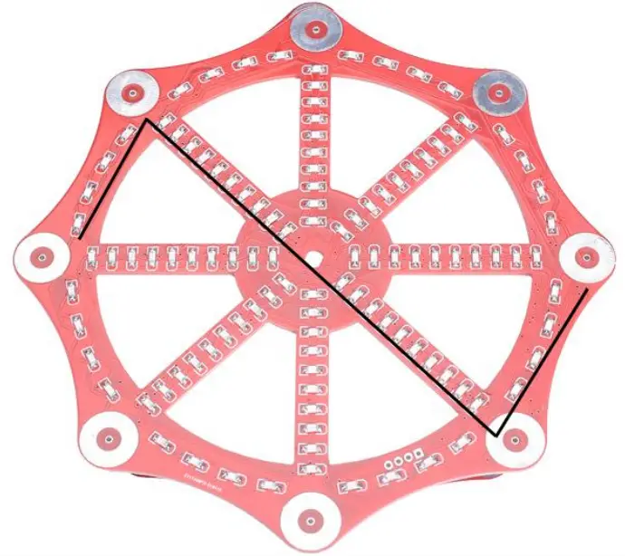
Step 9: Install 1pcs Infrared Receiver at HX1. Pay attention to the installation direction.
Step 10: Tear off the acrylic surface protective film.
Step 11: Fix 1pcs Acrylic Type-Y Bracket on Acrylic Bottom Plate by 2pcs M3+10mm Screw and 2pcs M3 Nuts.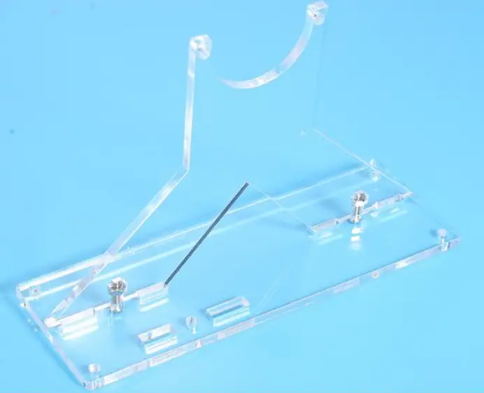
Step 12: Fix 2pcs M3+15mm Screw and 2pcs M3 Nuts and 4pcs M3 Pads on Acrylic Spring Fix Bracket.(Tips: Pads are use to connect wire and screw for Spring)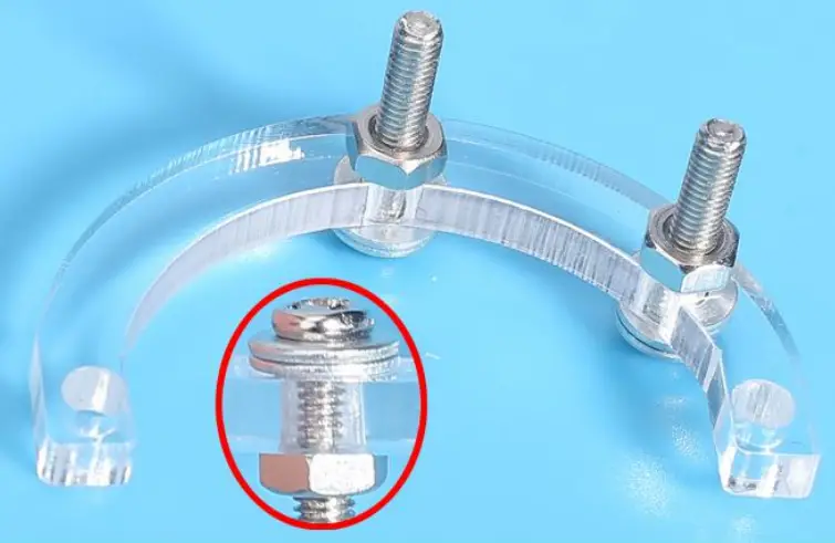
Step 13: Use the pads to clamp the red and black wires separately. Note that the red wire is connected to the pad near the middle of the acrylic. 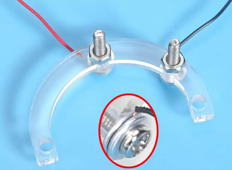
Step 14: Fix DC motor, Type-Y Bracket and Spring Fix Bracket by 2pcs M3+10mm Screw and 2pcs M3 Nuts. Pay attention to the installation order.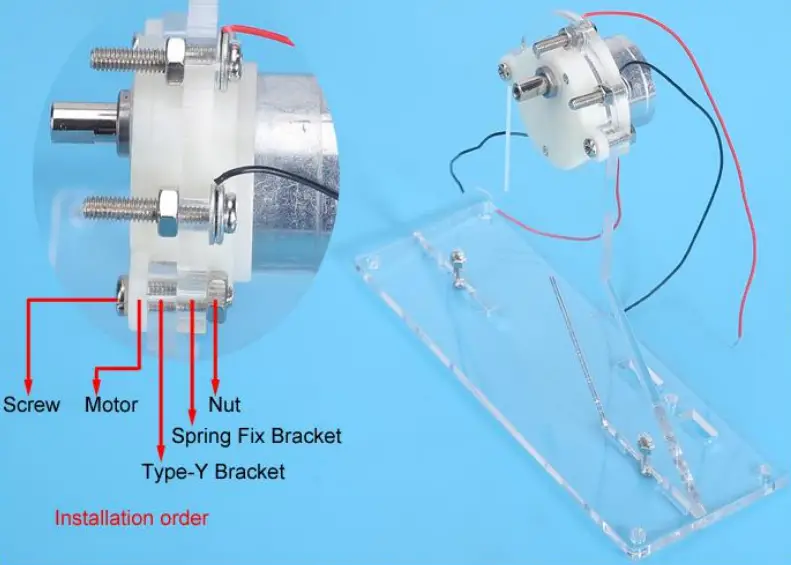
Step 15: Place 2pcs Spring on 2pcs M3+15mm Screws.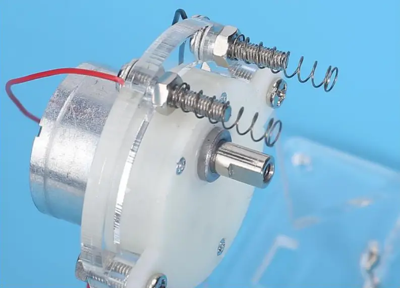
Step 16: Place PCB on motor shaft. Take care to adjust the position of the springs so that they touch the ring pad on PCB.
Step 17: Fix PCB on motor shaft by 1pcs Acrylic PCB Fix Bracket, 1pcs M3 Pad, ipcs M3 Nut.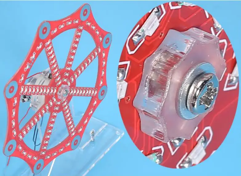
Step 18: Install 1pcs DC-005 Power Socket on Acrylic Switch Bracket and fix by comes with screw.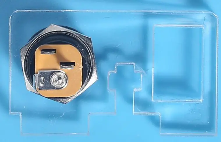
Step 19: Install ipcs Power Switch on Acrylic Switch Bracket.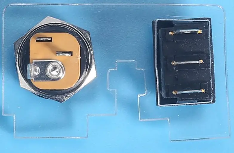
Step 19: Install 1pcs Power Switch on Acrylic Switch Bracket.
Step 20: Connect positive pole from DC-005 Power Socket and Power Switch by 10cm red Wire. Take care to select the correct pins.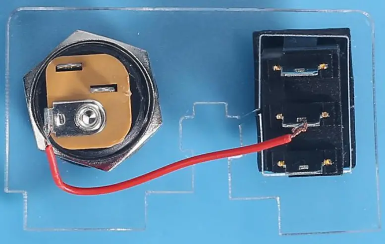
Step 21: Connect red wire form motor and pad to switch. Connect black wire form motor and pad to OC-005 Power Socket.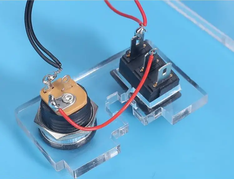
Step 22: Fix Acrylic Switch Bracket 1pcs M3+10mm Screw and tpcs M3 Nuts.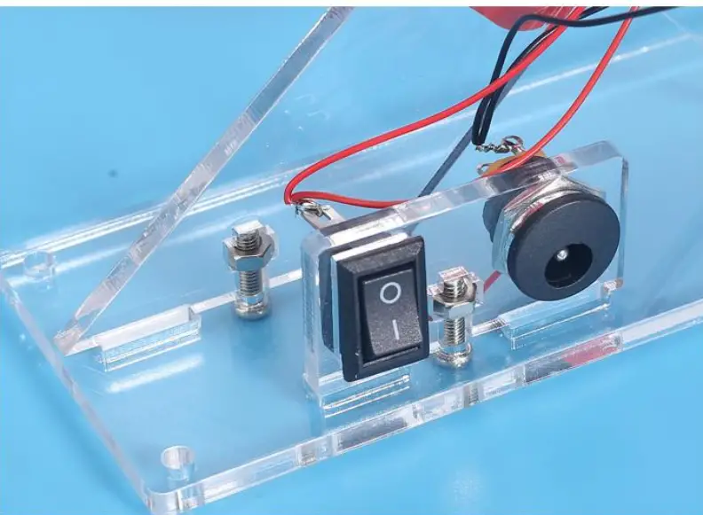
Step 23: Handling the LED pins. The short pins are slightly bent, the long pins are bent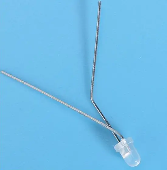
Step 24: The short pin insert the largest hole and the long pin insert the top smaller hole.
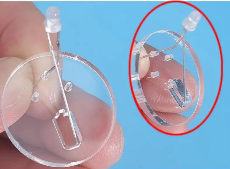
Step 25: Bend the LED to fit the LED into the largest hole.
Step 26: Bend the left pin so that it coincides with the small hole on the left and bending.
Step 27: Bend the left pin three times with pliers to make the shape shown in the picture.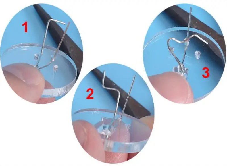
Step 28: Insert pin to the last hole.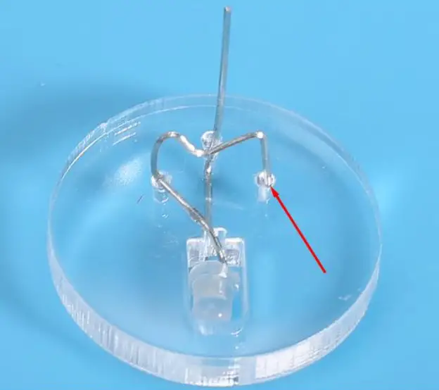
Step 29: Insert the other pin of the LED into the PCB. Bend the pin slightly on the back of the PCB, bend the pin slightly to keep it from falling off. Note: It cannot be fixed, otherwise it cannot be rotated.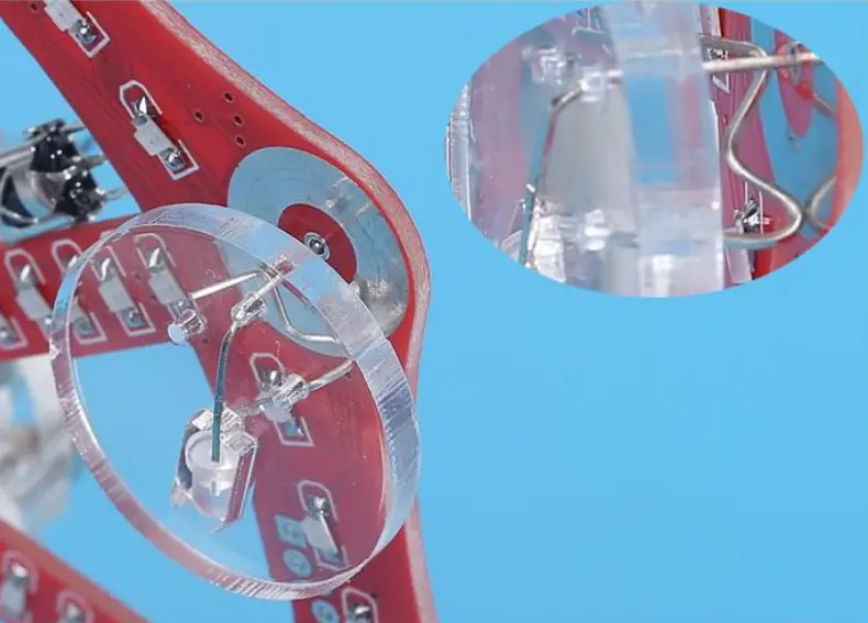
Step 30: In the same way, install other LED.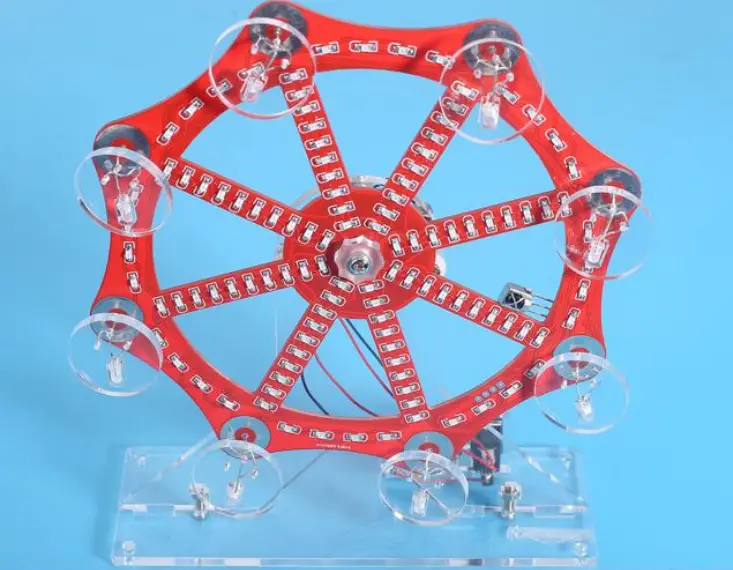
Step 31: Finally install 4pcs black pads on Acrylic Bottom Plate.