SUNPOWER 536685 SunVault Storage Torque Values

Installation Guide Appendix H
All conductors must be torqued and clearly paint marked. For conductor torque values into breaker terminals, see values specified on each breaker for the specific wire size (AWG) being used.
H.1 Hub+
For the Hub+ tables in this section, refer to the following numbered diagram: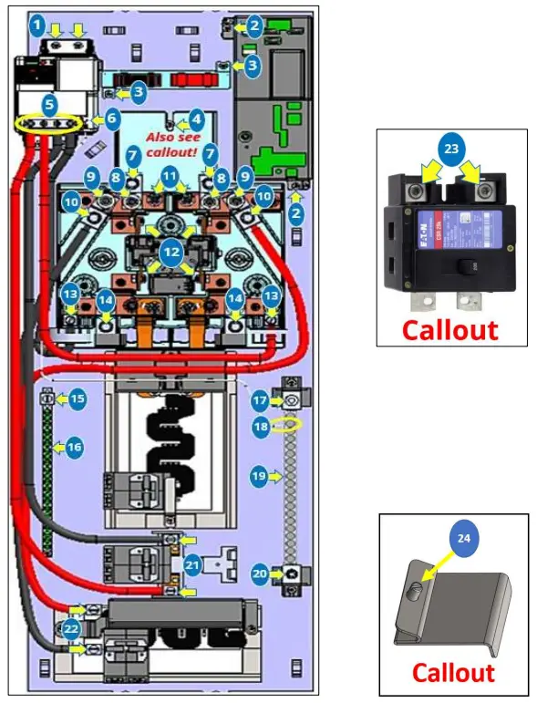
Hub+: Typical Field-Wired Terminations and Connections
| Connection | Tool | Torque | Diag. # | Torque Tool Range | ||
| in-lb | N-m | ft-lb | in-lb (ft-lb) | |||
| Hub+ PVS Plastic Cover Screws (quantity two, #6 screws) | T15 Torx (11-in-1) | 12 | 1.3 | 1.0 | N/A | 0 – 40 (0 – 4) |
| Hub+ Dead Front Screws | 5/16” nut driver (11-in- 1) | 12 | 1.3 | 1.0 | N/A | 0 – 40 (0 – 4) |
| Ungrounded Conductors into Top of Hub+ Factory Line-Side Lugs (L1/L2 incoming feeders) | 3/8” Allen | #1 AWG to 300 kcmil: 375 | 42.4 | 31.2 | 7 | 120 – 600 (10 – 50) |
| #1–#6 AWG: 275 | 31.1 | 22.9 | 120 – 600 (10 – 50) | |||
| Hub+ Ground Bar, Main Ground Lug | 5/16” standard (flathead) screwdriver | 2/O to #4 AWG: 50 | 5.6 | 41.6 | 15 | 120 – 600 (10 – 50) |
| Hub+ Ground Bar, Branch Circuit Wire Holes | #2 square | #14–#10: 20 #8: 25 #6: 35 #4: 45 | 2.2 2.8 3.9 5.0 | 1.6 2.1 2.9 3.7 | 16 | 0 – 150 (0 – 12) |
| Hub+ Neutral Bar, Main Neutral Lug | 1/4” Allen | 300 kcmil to #1 AWG: 50 | 5.6 | 4.1 | 17 | 0 – 150 (0 – 12) |
| Hub+ Neutral Bar, Branch Circuit Wire Holes | #2 square | #14–#10: 20 #8: 25 #6: 35 #4: 4 | 2.2 2.8 3.9 5.0 | 1.6 2.1 2.9 3.7 | 19 | 0 – 150 (0 – 12) |
| Hub+ Neutral Bar, Pass-Through Neutral Lug | 1/4” Allen | 2/O to #3 AWG: 50 #6–#4 AWG: 45 | 5.6 5.0 | 4.1 3.7 | 20 | 0 – 150 (0 – 12) |
| RPO cable conductors (ferruled conductors into green connector) | Precision flat screwdriver | 3 | .34 | NA | N/A | 0 – 40 (0 – 4) |
Hub+: When Field Changes Necessitate Engaging or Disturbing Factory Connections
| Connection | Tool | Torque | Diag. # | Torque Tool Range | ||
| in-lb | N-m | ft-lb | in-lb (ft-lb) | |||
| Hub+ Consumption CT Mounting Bracket to Hub+ Backplate (quantity two, 8/32” nuts) | 11/32” nut driver | 12 | 1.3 | 1.0 | 3 | 0 – 40 (0 – 4) |
| Optional Hub+ Main Breaker Ungrounded conductors into breaker (L1/L2 incoming feeders) | 1/4” Allen | #2 AWG to 300 kcmil: 250 | 28.2 | 20.8 | 23 | 120 – 600 (10 – 50) |
| Optional Hub+ Main Breaker Power tabs to Hub+ Line Side Busing (quantity two, 1/4”-20 threaded studs) | 7/16” socket | 48 | 5.4 | 4.0 | 11 | 0 – 150 (0 – 12) |
| Optional Hub+ main breaker Housing to Hub+ backplate (quantity one 8/32 nut) | 11/32” nut driver | 12 | 1.3 | 1.0 | 4 | 0 – 40 (0 – 4) |
| Hub+ MID Line-Side Factory Conductors to Hub+ Non- Backup Pan #1 AWG conductors into line lugs (L1/L2, if removed and used to wire to alternate flex subpanel or directly to flex pan 125 A breaker) | 3/8” Allen | #3 AWG to 250 kcmil: 375 | 42.4 | 31.2 | 10 | 120 – 600 (10 – 50) |
| #2–#6 AWG: 275 | 31.1 | 22.9 | 0 – 150 (0 – 12) | |||
| MID Load Side Lugs for Generation Pan Conductors into lugs (quantity two; L1 factory-routed through production CT) | 5/16” standard (flathead) screwdriver | #4–#6 AWG: 45 | 5.0 | 3.7 | 13 | 0 – 150 (0 – 12) |
| MID Load-Side Busing Lugs (Open lugs are hidden behind shroud—optional use to wire to alternate backed-up subpanel.) Important! Downstream subpanel must have OCPD if conductors are landed on these lugs instead of from a breaker in the Backup Pan. | 3/8” Allen | #3 AWG to 250 kcmil: 375 | 42.4 | 31.2 | 14 | 120 – 600 (10 – 50) |
| #2–#6 AWG: 275 | 31.1 | 22.9 | 120 – 600 (10 – 50) | |||
| Flex Pan Hold-Down Bracket (to hold down ESS or 125 A breakers) | Precision flat screwdriver | 10 | 1.1 | NA | 24 | 0 – 40 (0 – 4) |
Hub+: Additional Factory Connections
| Connection | Tool | Torque | Diag. # | Torque Tool Range | ||
| in-lb | N-m | ft-lb | in-lb (ft-lb) | |||
| PVDR to Hub+ Backplate (quantity four, 8/32 nuts) | 11/32” nut driver | 12 | 1.3 | 1.0 | 1 | 0 – 40 (0 – 4) |
| MIDC to Hub+ Backplate (quantity two 8/32 nuts) | 11/32” nut driver | 12 | 1.3 | 1.0 | 2 | 0 – 40 (0 – 4) |
| Ungrounded Conductors into PVDR (quantity four) | #2 Phillips screwdriver | 24 | 2.7 | 2.0 | 5 | 0 – 40 (0 – 4) |
| Grounded (Neutral) #16 AWG Conductor into PVDR | #0 Phillips screwdriver | 3 | 0.34 | 0.25 | 6 | 0 – 40 (0 – 4) |
| PVDR Grounded (Neutral) #16 AWG Conductor into Hub+ Neutral Bar | #2 square | 20 | 2.2 | 1.6 | 18 | 0 – 40 (0 – 4) |
| Hub+ Line-Side Feeder Lugs to MID Line Side Busing (quantity two 5/16-18 HH nuts; L1/L2 lugs) | 1/2” socket | 132 | 14.9 | 11.0 | 8 | 0 – 150 (0 – 12) |
| Hub+ Line-Side Lugs for Hub+ Non-Backup Pan, Line Lug to Line Busing (quantity two 5/16-18 HH nuts) | 1/2” socket | 132 | 14.9 | 11.0 | 9 | 0 – 150 (0 – 12) |
| Hub+ MID Contactor (quantity four, 1/4”-20 nuts and bolts) | 7/16” socket | 72 | 8.1 | 6.0 | 12 | 0 – 150 (0 – 12) |
| Generation Pan Conductor Terminals (feed comes from the PVDR) | 5/16” standard (flathead) screwdriver | #4 AWG: 45 | 5.0 | 3.7 | 21 | 0 – 150 (0 – 12) |
| Hub+ Non-Backup Pan Bus Lugs | 5/16” standard (flathead) screwdriver | 55 | 6.2 | 4.6 | 22 | 0 – 150 (0 – 12) |
H.2 ESS Enclosures
The following tables provide torque values for the ESS enclosure(s):
| Connection | in-lb | N-m | ft-lb | Torque Tool Range in-lb (ft-lb) |
| Battery Grounding Wire at Each Battery in Each ESS | 44 | 5.0 | 3.6 | 0–150 (0–12) |
| AC Terminals in Inverter Compartment and at Ground Bar | #14–#10 AWG: 35 | 3.9 | 2.9 | 0–150 (0–12) |
| #8 AWG: 40 | 4.5 | 3.3 | 0–150 (0–12) | |
| #6–#4 AWG: 45 | 5.1 | 3.7 | 0–150 (0–12) | |
| AUX cable conductors (ferruled conductors into green connector) | 3 | .34 | NA | 0–40 (0–40) |
| Battery Cables at Inverter DC Busbars in BASE ESS (only if ENERGY ESS is present) | 220 | 24.8 | 18.4 | 120–600 (10–50) |
| Battery Cables (DC) at ENERGY ESS Terminal Block (only if ENERGY ESS is present) | 87 | 9.8 | 7.2 | 0–150 (0–12) |
| AC Fan conductors at ENERGY ESS Terminal Block (only if ENERGY ESS is present) | 6 | 7 | NA | 0–40 (0–4) |
| Grounding Wire ENERGY ESS (only if ENERGY ESS is present) | #6 AWG: 35 #8 AWG: 25 | 3.9 2.8 | 2.9 2.1 | 0–40 (0–4) |
| ESS Pedestal Floor Mount Concrete Wedge Anchor Nuts (in concrete) | 480 | 54.2 | 40 | 120–600 (10–50) |
| ESS to Pedestal Mount Base Plate | 120–720 (0–60) | |||
| (quantity eight, 1/2″ bolts that secure the ESS to the mounting plate) | 685 | 77.3 | 57 | |
| SunPower DC Busbars into Inverter 3/8” bolt (only BASE ESS and only if disturbed) | 180 | 20.3 | 15.0 | 0–150 (0–12) |
| Inverter Chassis Ground Lug (factory- torqued but may be disturbed in field) | #6–#4 AWG: 45 | 5.1 | 3.7 | 0–150 (0–12) |
| #3–#2 AWG: 50 | 5.6 | 4.2 |


