![]() PRODUCT MANUAL
PRODUCT MANUAL
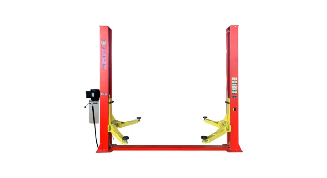
AGT-B1000 Two-Post Auto Lift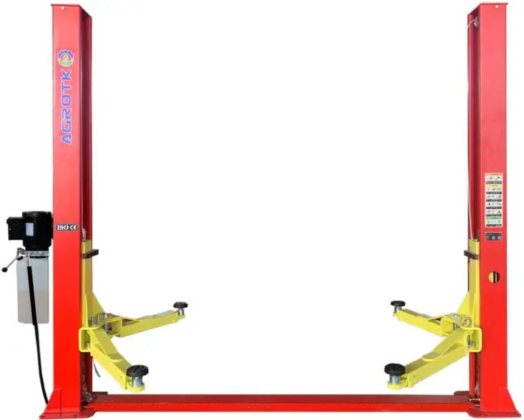
AGT-B1000 Two Post Auto Lift
![]() WARNING
WARNING![]()
- This equipment can not be installed, operated or repaired without reading instructions.
- Electricity must be hooked up by certified electrician.
- Do not use this equipment beyond its rated capacity.
Missing parts or questions on assembly?
Please contact us.
Equipment Description
1.1 Description
This 2 Post Floor Plate Lift is an advanced car maintenance equipment, mainly used for automotive’ s repair and maintenance.
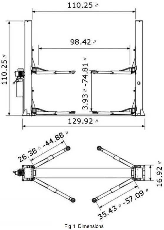
1 .2 Technical Specifications
| Lift Capacity | 4500kg / 10000lbs |
| Overall Height | 2800mm/110.25” |
| Overall Width | 3500mm/137.8” |
| Maximum Lifting Height W/ O Truck Adaptor | 1900mm / 74.81” |
| Minimum Height | 100mm / 3.93” |
| Lifting Time | 55s |
| Outside Column to Outside Column Width | 3300mm / 129.92” |
| Inside Column Width | 2800mm / 110.25” |
| Drive Through | 2500mm/98.42” |
| Column Thickness of Steel | 4.75mm / 0. 188” |
| Carriage Thickness of Steel | 4.75mm / 0. 188” |
| Arms Thickness of Steel | 5.5mm / 0.217” |
| Cable Diameter | 8.2mm / 0.323” |
| Voltage | 220v |
| Power | 2.2kw / 3hp |
| Breaker | 30A |
| Hydraulic Fluid Requirment | 3-5 Gallons AW32/AW46 |
| Equipment Weight | 565kg / 1253lbs |
Installation
This 2 Post Floor Plate Lift is the most common equipment for repairing cars. Its installation is not only related to the maintenance efficiency but also to personal safety of the maintenance technicians. Therefore, the installation must be completed by certified installers according to the User Manual, and in accordance with installation regulations. Recommend to use manufacturer supplied anchor bolts.
2.1 Preparation
2.1.1 Foundation
The lift must be installed on a level concrete foundation with a minimum concrete thickness of 6” (7.87 ” is recommended) and a strength of 3000 psi or more. The newly poured concrete needs to be dried thoroughly before installation. (Fig 2).
*Warning*: The size and concrete parameters of the foundation are the minimum strength and foundation depth parameters of the installation. The user needs to adjust the thickness and floor space of the foundation according to the maximum weight. It can also be done at the dealer’ s suggestion.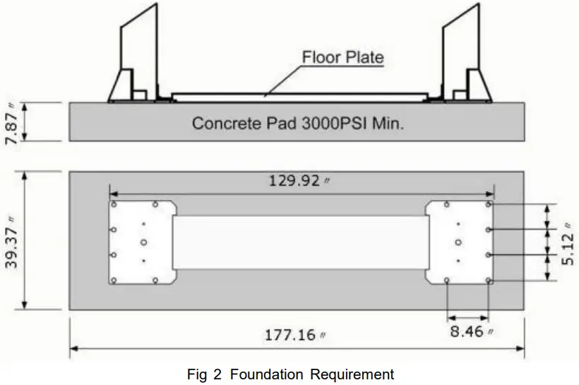 2.1.2 Tools Required
Hammer, Socket Wrench Set, Hex Wrench Set, Adjustable Wrench, Screwdriver, Measuring Tape( 1 6’+), Long-Nose Plier, Circlip Pliers, Electric Rotary Hammer, Drill(3/4”), Safety Glasses, Work Gloves, Safety Helmet, Forklift/ Crane or something similar.
2 .2 Equipment Installation
2.2.1 Install Columns
Stand up the 2 columns ( the column with the power unit base plate is the main column and the other one is the vice column)
Note: Don’t drill anchor bolts holes or install anchor bolts now.
2 . 2 . 2 Adjust Carriage
Raise the carriage to the 1 st locking position located at the bottom of the column( Fig 3 ) .
Note: You can hear “click” once locked (the 1st locking position is about 11.8” from the ground)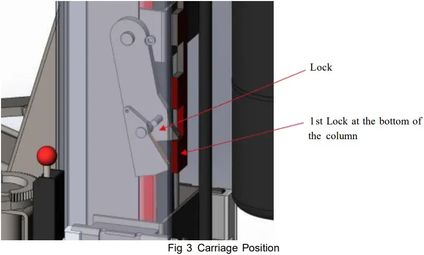 2.2.3 Install Cables (2 Cables in total)
Red & Blue color in this Fig are showing how to route the 2 cables ( Fig 4 )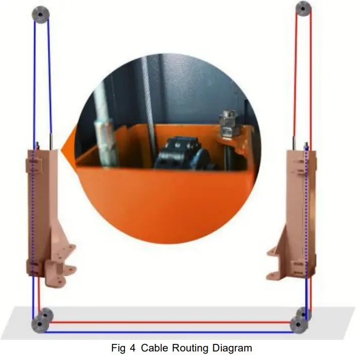 2.2.4 Install Hydraulic Hose (2 Hose in total)
Connect the longer hose in between the 2 cylinders, connect the short hose in between the cylinder and the power unit. Please hand tighten to avoid thread damage, then use hand wrench to fasten completely. (Fig 5)
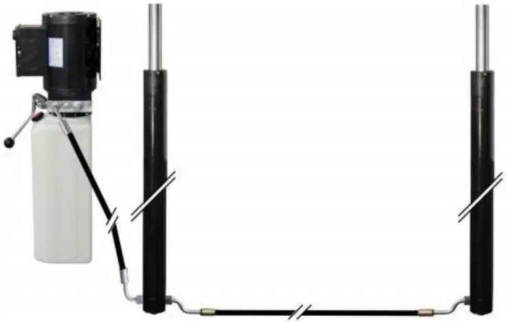 Fig 5 Hydraulic Hose Diagram
2.2.5 Install BasePlate (Fig 6)
Place the Baseplate inside the columns slots. ( No screws needed)
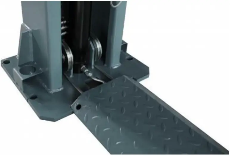 Fig 6 Baseplate Installation Diagram
2.2.6 Install Power Unit
Install power unit on the main column with M8 screws ( Fig 7 ) .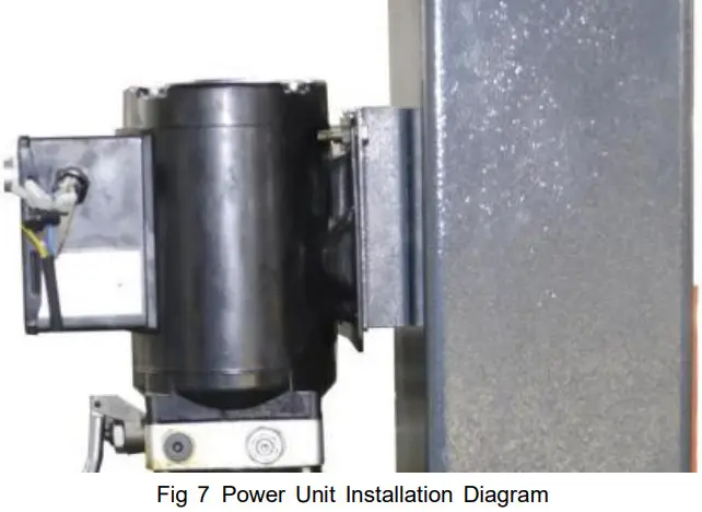 2.2.7 Install Anchor Bolts (Fig 8)
- Adjust the distance between 2 columns as required dimensions (Fig 1).
- Adjust the opening direction of the two columns in a straight line (visible).
- Install Anchor Bolts (Suggest to use 3/4” Drill)
Note: Don’ t Fasten/ Tighten Nuts now in case any adjustment needed. - Adjust the verticality of the columns (visible) and use U-shape washer(come with package) if necessary.
- Tighten anchor bolts nuts in diagonal order (Foot Pounds of Torque: 90+, suggest to use hand wrench to tighten nuts.)
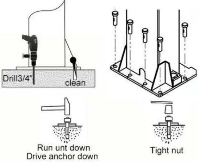 Fig 8 Anchor Bolts Installation Diagram
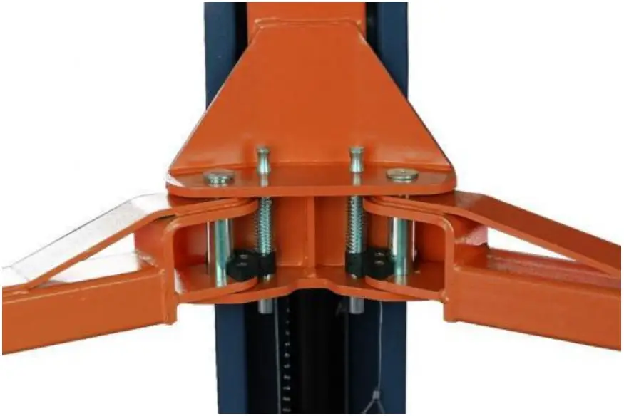
2.2.8 Install Arms and Pulling Rod
Install arms and pulling rod (Fig 9 and Fig 10).
 |  |
| Fig 9 Arm Installation Diagram | Fig 10 Pulling Rod Installation Diagram |
Check Before Start
3 .1 Mechanical Installation Check
- Check anchor bolts, nuts, fittings and etc have been installed properly.
- Check if all moving parts move freely.
- Make sure inside of the columns is clean and no other objects.
- Supply grease between slide blocks and columns, cables and pulleys.
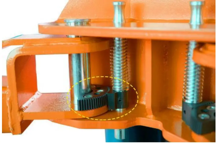
- Check if the arm lock is locked while raising processing, and adjust lock if necessary.
Note: Loose the screw to adjust when necessary(Fig 10).
3.2 Electrical Hook Up Check
Make sure all wiring are same as below circuit diagram ( Fig 1 1 ).
Attention: electrical system connection must be done by licensed electrician.
Warning When installing the power cord for the first time, remove the test cable( short wire) from the motor and replace it with a cable(wire) less than # 12 gauge.The time interval between motor starts is at least more than 2 seconds. Otherwise the motor or AC contactor may be burnt out.
suggest to use min 3 0 A breaker ( not higher than the wire load).
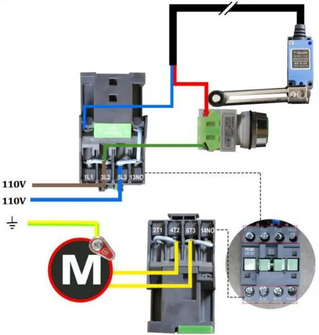 Fig 11 Power Unit Wiring Diagram (Voltage: 220V)
3.3 Hydraulic System Testing
- Add about 2 . 5 gallons of hydraulic oil to the hydraulic fluid reservoir, AW3 2 during winter time(cold weather), and AW46 during summer time(hot weather).
- Make sure there is no oil leak.
- Repeatedly raise and lower the lift to bleed trapped air from the cylinders.
- Power unit testing (Fig 12)
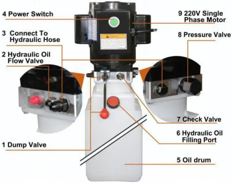 Fig 12 Power Unit Diagram
** Important Information**
7 Pressure Valve: Clockwise adjustment increases pressure to make the power unit to have more power, counterclockwise adjustment decreases pressure to make the power unit to have less power.
8 Hydraulic Fluid Flow Valve: Clockwise adjustment to speed up, counterclockwise adjustment to slow down.
3.4 Load Test
Before testing, check anchor bolts to make sure they are completely tightened, and also make sure 2 carriage on both sides are at the same level ( height difference should be less than 10mm/0.39”). Adjust the cable nut on the shorter carriage to make sure 2 carriage height at the same level and the 2 cables are similar tension.
Operation and Use
4.1 Operation
Place the lifting arm at the support point specified by the vehicle and adjust the rubber tray to the same height.
Check the position of the rubber tray under the vehicle chassis before each single raising or when vehicle is lowered to the ground and need to raise again.
4.2 Raising/Lifting
Press the power switch until the vehicle reaches desired height. When the vehicle is raised, the safety lock automatically engaged.
During raising/ lifting, check whether the arm lock has been locked, it can be visually checked when it is raised to a certain height (stop and check).
*Danger*: Unlocked arms can cause vehicle fall off from the lift.
4.3 Stopping
After raising to desired height, press the lower lever and the lift will automatically lower to a safe position, the safety lock will be engaged and the lift will be locked.
4.4 Lowering
The safety lock must be released before lowering.
- Press the power switch to raise the car by approximately 30mm/1.2” .
- Pull the safety lock release cables on both sides to unlock.
- Press the lower lever to start lowering process, the arm lock will be automatically released and allow the arm rotating when the vehicle is completely lowered to the ground.
Safety
Please read this manual carefully as it contains important safety information that the operators need to know.
*WARNING*: The design and construction of this lift is only suitable for lifting whole vehicle. All other uses are unauthorized, this lift CAN NOT be used to: wash vehicles, build lifting platforms, lifting personnel, use as cargo lifts and use as lifting partial of the vehicles.
5 .1 Important Reminder: Personal and Equipment Safety
- During vehicle lifting process, operators should be at a safe position/area.
- Turn off the vehicle engine and manual brake on.
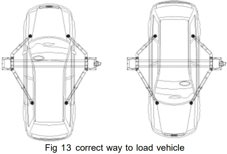
- Load vehicle correctly (Fig 13).
- The vehicle CAN NOT exceed the rated lifting capacity and required size.
 5.2 Vehicle Position
Once the vehicle is raised, vehicle CAN NOT be moved backwards or forwards as it may cause falling.
*WARNING*: Do not attempt to move the vehicle while it is parked on the lift.
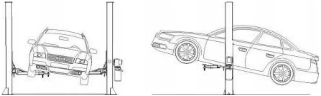 Fig 14 Risk of vehicle falling off
5 .3 Risk of Vehicle Falling Off From The Lift
Note that when positioning the vehicle on the lift, incorrect center of gravity of the vehicle can cause the vehicle falling off from the lift (Fig 14).
Important Note: Make sure that the front and rear of the vehicle need to be balanced and the cables on both sides also need to be balanced. Do not board/step on the vehicle or the lift when the lift is raised.
Below actions may cause the vehicle fall off from the lift (Fig 15)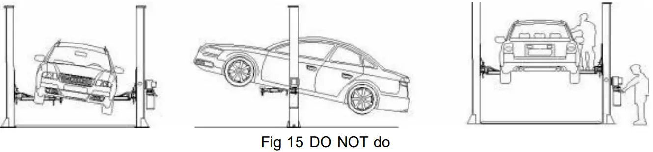
Maintenance
6.1 Every Month
Hydraulic System
- Check hydraulic oil level, fill hydraulic oil if necessary.
- Check the pump, hose and cylinder and see if there is hydraulic oil leaking.
6.2 Every 3 Month
Safety Maintenance
- Check the condition of the safety lock and the wear of the stop block.
- Check the anchor bolts, tighten nuts if necessary.
- Check if any nuts are loose, tighten nuts if necessary.
- Check if the arm locking system is working properly.
- Lubricate/grease all moving parts.
- Check the tension of the balance cables and check if there is any broken.
- Check if the 2 carriage on both sides are at the same level.
6.3 Every 6 Month
Hydraulic Pump
- Check the condition and aging of the hydraulic fluid. Unqualified hydraulic fluid is the main reason to cause valve failure and reduces the life of the gear pump.
- Check the noise variation of the motor and gear pump while normal operating.
6.4 Every 12 Month
- Visually inspect all structural and mechanical parts to make sure there is no abnormalities have occurred.
- Check and see if there is anything wrong with the motor, wiring, top limiter switch and circuit breaker.
6.5 Regular Lubrication
Use high quality grease to regularly lubricate all moving parts of this lift.
Troubleshooting Guide
| Malfunction | Possible reason | Solution |
| The motor does not work | 1. Check the air switch. 2. Check if the voltage is correct. 3. The motor burned. 4. Start switch burned. 5. Top limiter switch burned. 6. AC contactor burned. | 1. Turn off or replace the air switch. 2. User correct power supply. 3. Replace the motor. 4. Replace the start switch. 5. Replace the top limiter switch. 6. Replace the AC contactor. |
| The motor works but can’t lift | 1. Pressure valve pressure is too small. 2. Pump station takes in air. 3. Hydraulic oil suction hose is detached or broken. 4. Insufficient hydraulic oil | 1. Colockwise adjust the pressure valve (fine adjustment). 2.Unscrew check valve on the power unit, and then start the motor until hydraulic oil flows out from the check valve, then tighten the check valve. 3. Install/replace the suction hose. 4. Fill more hydraulic oil. |
| Does not lowering | 1. Safety lock engaged 2. Other object inside the columns stops the carriage. 3. The flow valve needs to be adjusted. | 1. Slightly raise the device and then pull the safety lock release cable. 2. Check and remove the objects. 3. Counterclockwise adjust the flow valve( fine adjustment) . |
| Self- Lowering | 1. Dump valve failure. 2. Hydraulic oil leaks. 3. The valve body of the power unit has holes. | 1. Replace the dump valve. 2. Check and repair. 3. Replace the valve body. |
| Raise without load, but does’t raise with load | 1. The voltage is too low. 2. Objects in the dump valve. 3 .The pressure valve pressure is too small. 4 .Overload. | 1. Install the voltage stabilizer. 2. Remove objects from the dump valve. 3. Increase pressure properly (fine adjust the pressure valve). 4. This operation is prohibited. |
| Lifting is not leveled | 1. The cables are not balanced. | 1. Balance cables by adjusting the cables’ length. |
| Loud motor noise | 1. After raising to the highest point, the motor is still working and the top limiter switch is disabled. 2. Hydraulic oil pollution. 3. Overload. | 1. Replace the top limiter switch. 2. Replace the hydraulic oil. 3. This operation is prohibited. |
Structure and Parts List
8.1 Equipment Assembling Diagram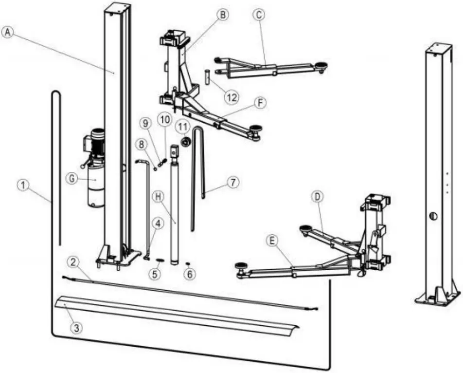
| NO. | Name |
| A | Column |
| B | Carriage |
| C | Arm |
| G | Power Unit |
| H | Cylinder |
| 1 | Cable |
| 2 | Hydraulic Hose |
| 3 | Baseplate |
| 4 | Hydraulic Hose |
| 5 | Hose Fitting |
| 6 | Hose Fitting |
| 7 | Chain |
| 8 | Circlip Φ25 |
| 9 | Oil Free Bearing |
| 10 | Chain Wheel Shaft |
| 11 | Chain Wheel |
| 12 | Arm FSixed haft |
8.2 Carria e Structure Dia ram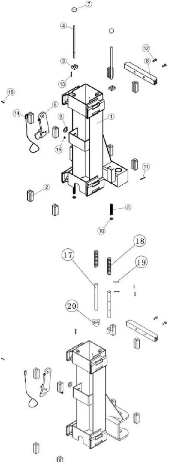
| NO. | Name |
| 1 | Carriage |
| 2 | Slide Block |
| 3 | Lock Gear |
| 4 | Unlocking Lever |
| 5 | Unlocking Lever Compression Spring |
| 6 | Door Guard |
| 7 | Knob |
| 8 | Mechanical Lock |
| 9 | Washer Φ25 |
| 10 | Washer Φ10 |
| 11 | Cotter Pin Φ3X30 |
| 12 | Bolt M8X25 |
| 13 | B- Shape Circlip |
| 14 | Safety Lock Release Cable |
| 15 | Hexagon Socket Bolt M8X20 |
| 16 | Nut M8 |
| 17 | Inner Hanging Fork Shaft |
| 18 | Spring Φ26/ 140/Φ2 |
| 19 | Pin Φ5×32 |
| 20 | Inner Hanging Small Arm Lock |
8.3 Column Structure Dia ram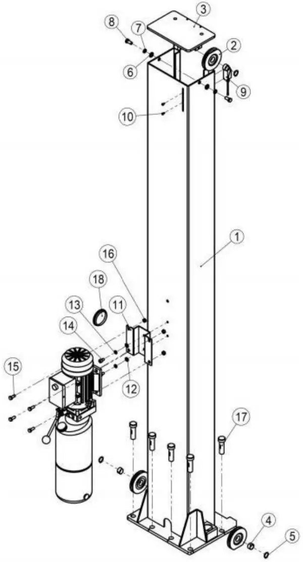
| NO. | Name |
| 1 | Column |
| 2 | Pulley |
| 3 | Cover |
| 4 | Oil Free Bearing |
| 5 | Shaft Circlip Φ25 |
| 6 | Flat Washer Φ10 |
| 7 | Spring Washer Φ10 |
| 8 | Outer Hexagonal Bolt M10 X35 |
| 9 | Top Limiter Switch |
| 10 | Bolt M5X10 |
| 11 | Motor Base Plate |
| 12 | Flat washer Φ10 |
| 13 | Spring Washer Φ10 |
| 14 | Hexagon Socket Bolt M10X12 |
| 15 | Outer hexagonal Bolt M8X20 |
| 16 | Nut M8 |
| 17 | Anchor Bolts |
| 18 | Access Window Cover |
8.4 3- stage arm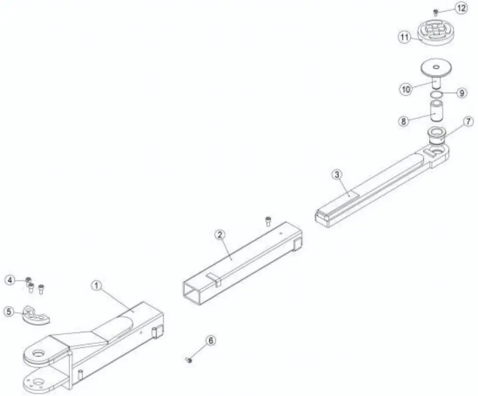
| No | Part# | Name | Qty |
| 1 | DNLM-05-01-00 | Inner arm of three stage arms | 2 |
| 2 | DNLM-05-02-00 | Middle arm of three stage arms | 2 |
| 3 | DNLM-05-03-00 | Outer arm of three stage arms | 2 |
| 4 | IH001020 | Inside hex bolt M1 0 X2 0 | 6 |
| 5 | DBLM-00-25 | Moon gear | 2 |
| 6 | IH000810 | Inside hex bolt M8 X1 0 | 4 |
| 7 | DBLM-00-26 | Sleeve of one stage screwed pad | 2 |
| 8 | DBLM-00-27 | Exte nsion | 2 |
| 9 | DBLM-00-28 | Stop steel ring externalΦ 2 0 | 2 |
| 10 | DBLM-00-29 | Screwed pad | 2 |
| 11 | DBLM-00-30 | Rubber cover | 2 |
| 12 | IH001020 | Inside hex bolt M10X20 | 2 |
8.5 2-stage arm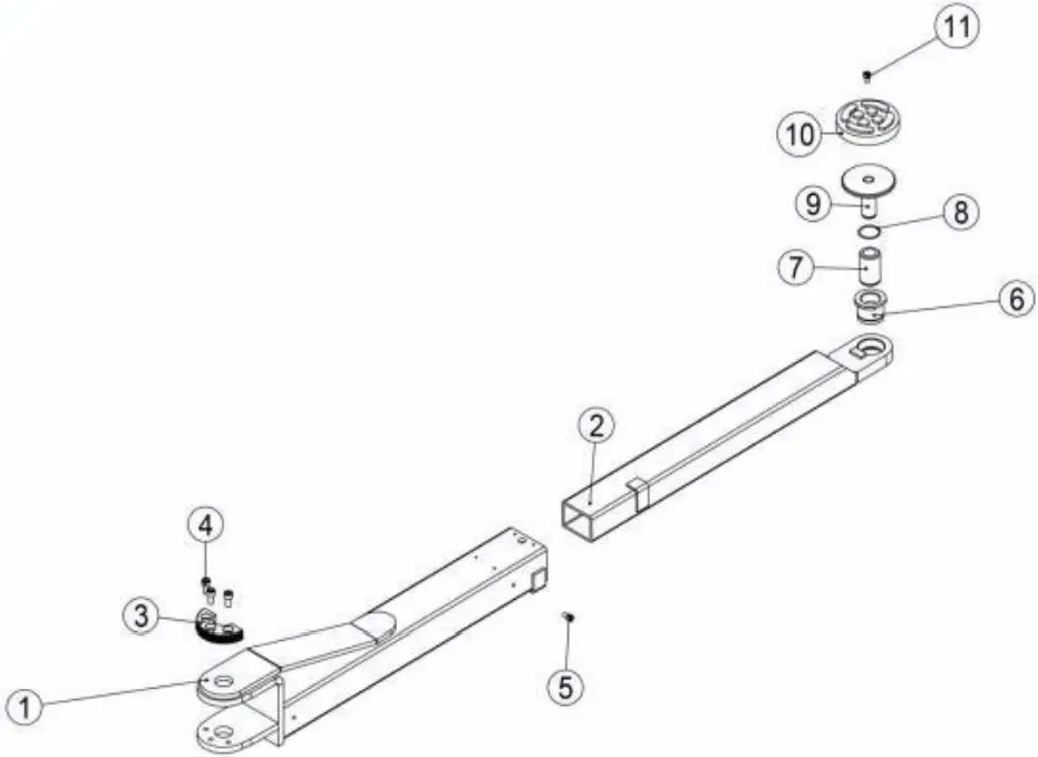
| No. | Part# | Name | Qty |
| 1 | DBLM-06-01-00 | Inner arm of two stage arms | 2 |
| 2 | DBLM-06-02-00 | Outer arm of two stage arms | 2 |
| 3 | DBLM-00-25 | Moon gear | 2 |
| 4 | IH001020 | Inside hex bolt M1 0 X2 0 | 6 |
| 5 | IH000820 | Inside hex bolt M1 0 X1 0 | 2 |
| 6 | DBLM-00-26 | Sleeve of one stage screwed pad | 2 |
| 7 | DBLM-00-27 | Extension | 2 |
| 8 | DBLM-00-28 | Stop steel ring externalΦ 2 0 | 2 |
| 9 | DBLM-00-29 | Screwed pad | 2 |
| 10 | DBLM-00-30 | Rubber cover | 2 |
| 11 | IH001020 | Inside hex bolt M10X20 | 2 |
![]()


