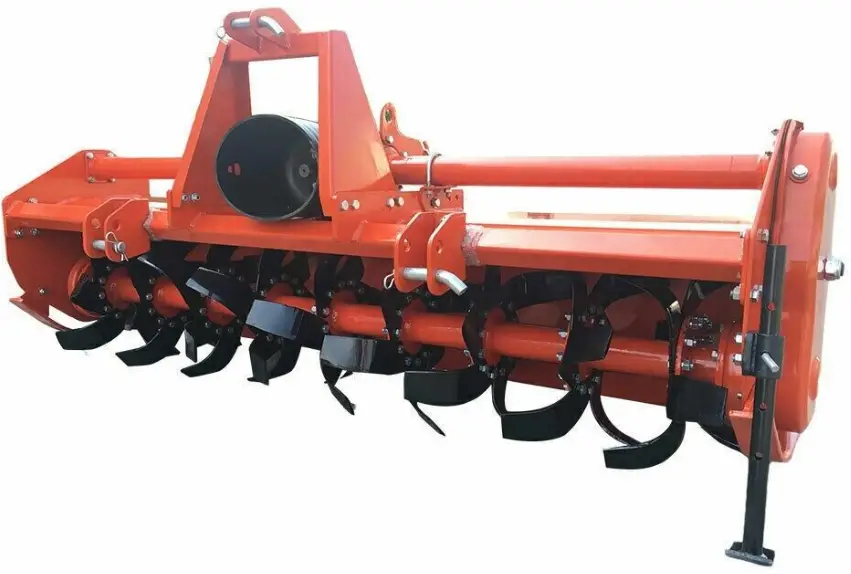
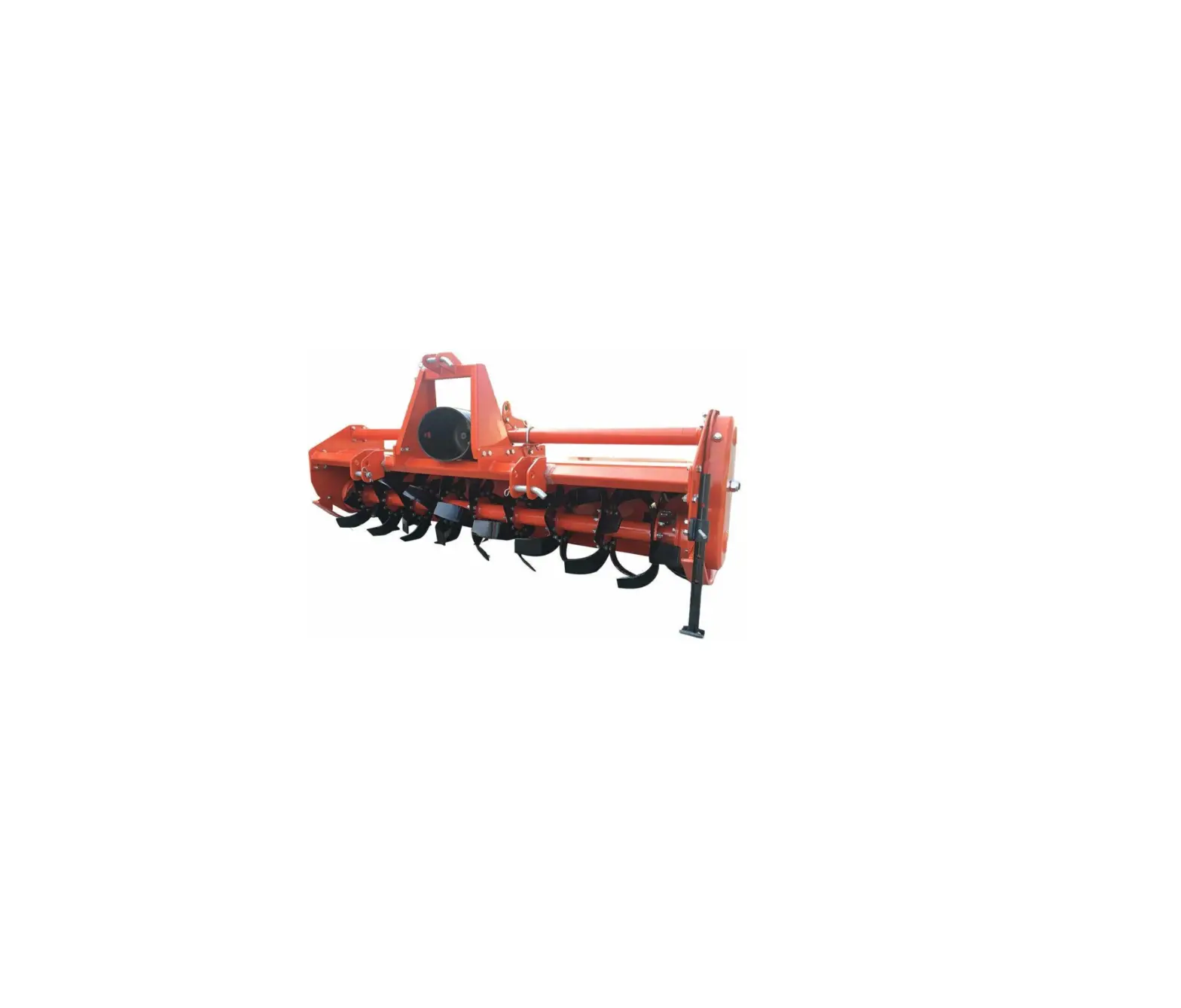
Home » Blog » Agt Industrial Agt-tas74-81 Tractor Rototiller Owner's Manual Agt Industrial Agt-tas74-81 Tractor Rototiller Owner's Manual Contents hide1 AGT Industrial AGT-TAS74-81 Tractor Rototiller2 TO THE OWNERS2.1 GENERAL COMMENTS2.2 BEFORE OPERATION2.3 SERVICE3 SAFETY PRECAUTIONS3.1 BEFORE OPERATION4 SAFETY PRECAUTIONS4.1 Operator Safety4.2 Tool Safety4.3 Maintenance Safety5 SAFETY PRECAUTIONS5.1 Wear Protective Equipment5.2 Transportation and Storing6 ROTOTILLER ASSEMBLES7 DRIVE SHAFT ASSEMBLES8 OPERATION INSTRUCTIONS9 OPERATION INSTRUCTIONS10 NOTES11 Documents / Resources11.1 References12 Related PostsAGT Industrial AGT-TAS74-81 Tractor RototillerTO THE OWNERSGENERAL COMMENTSCongratulations for having this Tractor Rototiller ! Your Tractor Rototiller wascarefully designed and manufactured to give you years of dependableservice. Your Tractor Rototiller will require some minormaintenancetokeepit in top working condition.Please observe all safety precautions and maintenance proceduresasdescribed in this manual.BEFORE OPERATIONThoroughly read and understand the instructions given in this manual beforeoperation. Refer to the “Safety Label” section, read all instructions notedonthem.Do not allow anyone to operate his equipment who has not fully readandcomprehended this manual and who has not been properly trainedinthesafe operation of the equipment.SERVICEPlease remember to use only manufacturer replacement parts. Substituteparts may not meet the standards required for safe, dependable operation.SAFETY PRECAUTIONSBEFORE OPERATIONThe operator must read the operation manual carefully beforeinstallation, operation or maintenance. Improper operation will causethemachine damage or the operator death.Read all the safe signs and safe declarations. Follow all the professional safe terms, local laws or the professional directions.Familiar with the Tractor Rototiller about functions, specs and operation. Replace the to-be-damaged parts in time. Make sure all the hydraulicinstallations and couplings connect firmly, and all the safe signs stick onthesuitable positions clearly. IMPORTANTOperator should be familiar with all functions of the unit.Make sure all guards and shields are in place and secured beforeoperatingimplement.Keep all persons away from equipment and work area.Dismounting from a moving unit can cause serious injury or death.Keep hands, feet, and clothing away from power-driven parts.Detach and store implement in an area where children normally donot play. Secure implement by using blocks and supports.Always wear proper safety glasses, goggles, or a face shield whendriving pins in or out, or when any operation causes dust, flyingdebris, or any other hazardous material.SAFETY PRECAUTIONSOperator Safety►Wear protective clothing and equipment appropriate for the job. Clothingshould be snug fitting without fringes and pull strings to avoid entanglementwith moving parts.►Prolonged exposure to loud noise can cause hearing impairment orhearing loss. Wear suitable hearing protection such as earmuffs or earplugs.►Operating equipment safely requires the operators all attention, Avoidwearing radio headphones while operating machinery.Tool Safety►Inspect entire machine before each use. Replace damaged or wornparts.►Check for fuel leaks and make sure all fasteners are in place andsecurelyfastened.Maintenance Safety►Maintain according to recommended procedures included in this manual.►Disconnected the spark plug wire before performing maintenance.►Stop engine before removing fuel cap.►Use only genuine replacement parts of the engine manufacturer.SAFETY PRECAUTIONSWear Protective Equipment►Escaping fluid under pressure can penetrate the skin causing serious injury.►Avoid the hazard by relieving pressure before disconnecting hydrauliclinesor performing work on the system.►Make sure all hydraulic fluid connections are tight and all hydraulic hosesand lines are in good condition before applying pressure to the system.►Use a piece of paper or cardboard, NOT BODY PARTS to checkforsuspected leaks.►Wear protective gloves and safety glasses or goggles when workingwithhydraulic systems.►DO NOT DELAY. If an accident occurs, see a doctor familiar with this typeofinjury immediately. Any fluid injected into the skin or eyes must betreatedwithin a few hours or gangrene may result.Transportation and Storing►Always shut off the fuel valve and engine.►Always allow engine to cool.►Store machine and fuel where fuel vapors cannot reach sour combustionlike, water heaters, electric motors, switches, furnaces, etc.►Always secure the machine with tie downs or similar restraints whentransporting.►The machine be stored in a manner that prevents it fromfalling, rollingortipping.ROTOTILLER ASSEMBLESS/NPART NO.PART DESCRIPTIONQTYSNOTE1Bolt M10*25GB/T5783-200041ABolt M0*25GB/T5783-200031BBolt M10*25GB/T5783-200032Frame WeldmentTS-81-01-01-0012Frame WeldmentTS-74-01-01-0012Frame WeldmentTS-66-01-01-0012Frame WeldmentTS-58-01-01-0012Frame WeldmentTS-50-01-01-0013split pinTS-66-01-02-0334Lower Hitch BlockTS-66-01-02-0225Lower Hitch ConnectingSeat PanelTS-81.01.02. 01-0225Lower suspension connecting plate WeldmentTS-81.01.02. 0125Lower suspension connecting plateWeldmentTS-50/58/66/7426V BoltTS-66-01-02-0127Bolt Ml2*35GB/T5783-2000107ABolt Ml2*35GB/T5783-200027BBolt M2*30GB/T5783-200028U BoltTS-66-03-0129Support – Drive shafthousingTS-66-03-02210ASupport – GearboxShieldingTS-66-02-02-02110BBoltGB/T5783-2000310CGearbox ShieldTS-66-02-02-01111A FrameTS-66-01-03-01-00112Top Hitch PinTS-66-01-03-01113Bolt Ml0*20GB/T5783-2000413ABolt M10*25GB/T5783-2000413BBolt M10*25(4)M10*30 (2)GB/T5783-2000613CBolt M10*25GB/T5783-2000214Gearbox Support TubeTS-81-04-00114Gearbox Support TubeTS-74-04-00114Gearbox Support TubeTS-66-04-00114Gearbox Support TubeTS-50/58-04-00115Floating Seal 72*35*10HG4-692-67116Snap Ring 072GB/T893. 1-1986117Bearing 6207GB/T276-1994218Pinion GearTS-66-02-05119Bolt M8*16GB/T5783-2000420Gearbox Oil Plug (Dip Stick) 121Housing – GearboxTS-66-02-01122Bearing 6307GB/T276-1994123SpacerTS-66-02-04124Gasket Bearing Cover(102*^75*0. 5) TS-66-02-03 125Bearing CoverTS-66-02-02126Breather Cap 5126AAdd Oil Bolt Ml6*1. 5127Bolt M8*25GB/T5783-20001628Side Drive CoverTS-66-08-01-00129Gasket – Gear/Chain CoverTS-66-08-01130Snap Ring Ext.GB/T894. 2-1986231Output Gear Shim32Input GearTS-66-02-09133Gasket-Driving GearTS-66-02-08134Drive ShaftTS-81-02-10134Drive ShaftTS-74-02-10134Drive ShaftTS-66-02-10134Drive ShaftTS-58-02-10134Drive ShaftTS-50-02-10135Bearing 6308GB/T276-1994236Bolt Ml0*30GB/T5783-2000636ABolt Ml2*25GB/T5783-2000637Side Panel – LeftTS-66-01-04-00138Gasket – Drive shaft(151*136*0. 5)TS-66-02-07239Drive Shaft Tube HousingTS-81-02-01-00139Drive Shaft Tube HousingTS-74-02-01-00139Drive Shaft Tube HousingTS-66-02-01-00139Drive Shaft Tube HousingTS-58-02-01-00139Drive Shaft Tube HousingTS-50-02-01-00140Lifting HookTS-66-02-11141Oil Seal – Drive shafttube housing40*65*8HG4-692-67142Ring GearTS-66-02-06144Drain Plug145Lock Nut M24*l. 5146O-Ring023. 6*3. 55GB/T3452. 1-2005147Bearing 30306GB/T297-1994248Snap Ring 072GB/T893. 1-1986149Idler GearTS-66-08-02150Plain Washers 030151Lock Nut M35*1.5152Retaining Washer 035GB/T858-1988153Bottom GearTS-66-08-04154ShimTS-66-08-06155Snap Ring 0100GB/T893. 1-1986156Gasket – Rotor(168*115*0. 5)TS-66-08-08157Bearing 6309GB/T276-1994158Oil Seal 80*50*12HG4-692-67159Bearing Support – Left SideTS-66-08-05160Rotor Support shaftTS-66-08-07161Rotor Shield-LeftTS-66-08-09162Bolt M12*35GB/T5783-2000662ABolt M12*30GB/T5783-2000663Bolt M2*1. 25*35GB/T5786-20009664Tiller Blade2-012.4 pitch 42. 44865Rotor WeldmentTS-81-09-01-01-00165Rotor WeldmentTS-74-09-01-01-00165Rotor WeldmentTS-66-09-01-01-00165Rotor WeldmentTS-58-09-01-01-00165Rotor WeldmentTS-50-09-01-01-00166Dust Cover-RightTS-66-09-01167Rotor Support shaft – RightsideTS-66-09-03168Oil Seal 62*45*12HG4-692-67169Bearing SupportTS-66-09-04170Retaining WasherTS-66-09-08171Bolt 2*20GB/T5783-2000172Dust Cover-RightTS-66-09-02173End Cap – Rotor Right sideTS-66-09-07174Bolt Ml 0*35GB/T5783-2000475Grease Fitting Ml 0*1176Pin – StandTS-66-05-01177R-Clip – StandTS-66-05-02178Stand BracketTS-66-05-02-00179Stand LegTS-66-05-01-00180Skid WeldmentTS-66-06-00181Bolt Ml 6*90282TailgateTS-81-07-01-00182TailgateTS-74-07-01-00182TailgateTS-66-07-01-00182TailgateTS-58-07-01-00182TailgateTS-50-07-01-00183Tailgate Chain assemblyTS-66-07-02-01184Side Panel – RightTS-66-01-01185Gasket 2 (0119*0*95*0. 5)TS-66-09-06186Gasket 1( 150* 108*0. 5)TS-66-09-05187Shim 2T*.04-021DRIVE SHAFT ASSEMBLESS/NPART NO.PART DESCRIPTIONQTYSNOTE16 Spline Yoke for tractor side12Pin Ф13*4713Spring Ф0.9*2514Circlips Ф2785U.joint 27×74.526Outer tube yoke17pin Ф10*6518Triangle Outer tube19Outer shield cone110Outer shield bearing111Outer shield tube111Inner shield tube112Inner shield bearing113Inner shield cone114Safety Chain215Bolt M10*95616Spring Ф6.5*46617Washer Ф10618Nylon self-locking nut M10619blind flange120driven plate121Friction disk222Bolt M12*70223Washer Ф12224Nylon self-locking nut M12225flange126Nylon bushing127Clutch Yoke128Inner tube Yoke129Pin Ф10X60130Triangle Inner tube1OPERATION INSTRUCTIONS Check the unit before attaching the rotary tiller to the tractor to ensure thereis oil inthe top and side gear box. See Maintenance section for lubricant specifications.Check the oil grease points before starting operationOil level: Top gearbox 1 1/2” from the end of the dip stick. When sitting slightly tilted forward, oil should at the bottom of the fill plug on the side gearboxcover. Grease: Right Rotor bearing, PTO shaft Cross & BearingsAttaching to the tractor With the Rotary Tiller on a level surface, back the Cat. 1 tractor so the tractor lift arms areeven with the unit’s lower hitch pins. Lower or raise the tractor hitch arms until the 7/8” bushingin the arm is inside the clevis of lower hitch points. Be sure nothing is between the tractor andthe tiller before backing up.Insert the lower hitch pin through the lower hitch blocks and the tractor arm. The YCT seriestillers have adjustable lower hitch blocks that can be slide to facilitate usage on larger tractors.Secure the lift arm in place by using a 7/16” lynch pin or other fastener.Repeat with the other arm.Connect the driveline to the tractor’s PTO output shaft. Secure it in place.Connect the tractor top link to the upper hitch point of the rotary tiller.Start the tractor and slowly raise the tiller. Check for drawbar interference. Be sure that the PTOdriveline does not bottom out when lifting the machine to it’s maximum height. If it does appearthat it could bottom out, it is necessary to shorten the PTO driveline. (See Shortening a PTODriveline section). Ensure that in the working position there is an overlap of a minimumof 1/3the length of each profile.Shortening a PTO DrivelineWith the implement attached to the tractor’s three point hitch, and the PTO driveline not installed, separate the PTO driveline. Attach the implement end to the implement and the other end to the tractor PTO input shaft.Raise the implement by using the tractor’s hydraulic 3-point hitch to it’s maximum lift height.Hold the half shafts next to each other and mark them so each end is approximately ½” from hitting the end of the telescopic profiles.Shorten the inner and out guard tubes equally. 5. Shorten the inner and outer profiles by the same length as the guard tubes. Using a rat tail file, roundoff all sharp edges and burrs. Grease the telescopic profile generously before reassembling Do not shorten too much, the proper overlap is a minimumof 1/3 thelength of each profile.OPERATION INSTRUCTIONS Caution: Slip Clutches may get hot. Do Not Touch. Keep the slip clutchareaclear of an material that may catch fire.Slip clutches have adjustable torque settings. The torque setting varies with the differentcompression of each spring. All the springs should have an equal amount of compressionIMPORTANT: Do not over-tighten the compression nuts as this may impair performance or causepremature wearing of the slip clutch.Slip Clutch adjustmentsUsing a marker, scribe a line across the exposed edges of the clutch plate and friction discs.Back off compression nuts to free friction discs by turning each nut exactly 2 revolutions.Start the tractor and run the driveline at a low idle to slip the friction discs. This will remove the dirt, corrosion and surface floss from the clutch plate faces.Disengage PTO, shut down the tractor and wait for all components to come to a complete stop.Inspect the clutch and ensure that the scribed markings on the disc and plates have changed position. If any two marks are still aligned, this is an indication that these discs have not slipped. It may needtocompletely disassemble the clutch to free them up.After ensuring all discs are free, tighten the compression nuts, uniformly, exactly 2 revolutions to resent theclutch original pressureWorking Depth AdjustmentThe working depth is controlled by raising or lowering the side skids. If the skids are raised, the workingdepth increases. By lowering the skids, the tilling depth with decrease.Tailgate adjustmentThe tailgate can be adjusted to help smooth and compact the tilled ground. Release the chain and secure to the desired height.Start upAfter making the necessary adjustments, lower the rotary tiller until the blades are a couple of inches from the ground. Engage the PTO and slowly lower the tiller to begin working.Removal and StorageAfter finishing, remove the rotary tiller from the tractorPut the PTO driveline in a safe location to avoid damage.Clean and dry the equipment.Replace any damaged or worn parts.Check all bolts and nuts for tightness.Lubricate and protect the machine from the elementsNOTES[email protected]https:\\www.agrotkindustrial.com References agrotkindustrial Documents / Resouces Download manual Here you can download full pdf version of manual, it may contain additional safety instructions, warranty information, FCC rules, etc. To access the pdf donwload links, solve the captcha. Related Manuals Agt Industrial Agt-tas74 3 Point Linkage Tractor Rototiller Owner's Manual Al-ko 92hd Garden Tractor User Manual Agt Industrial Agt-wb24 Wheel Balancer Owner's Manual Agt Industrial Agt-exflm115 Excavator Flail Mower Owner's Manual Fendt X991019010000 Happy Tractor Instruction Manual John Deere Omgx23532 J0 Tractors User Manual John Deere Omm162468 Equipment Division User Manual Craftsman 917.28921 Lawn Tractor User Manual Craftsman 917.273142 Lawn Tractor User Manual Craftsman 917.28936 Lawn Tractor User Manual John Deere D140 Lawn Tractor User Manual Craftsman 917.28910 Lawn Tractor User Manual John Deere 676 7000 Series Owner's Manual 2052l Tractor Falk With Trailer Owner's Manual Texas Xc140-98 Lawn Tractor User Manual Craftsman 247.28841 Lawn Tractor User Manual Al-ko T16-105.6 Hd V2 Garden Tractor 127370 Instruction Manual Craftsman 28857 Lawn Tractor User Manual Craftsman 917273180 Lawn Tractor User Manual Craftsman 917273180 Lawn Tractor User Manual