![]() PRODUCT MANUAL
PRODUCT MANUAL
3 Point Linkage Tractor Rototiller
Model:AGT-TAS74/81
Ver.1.1.3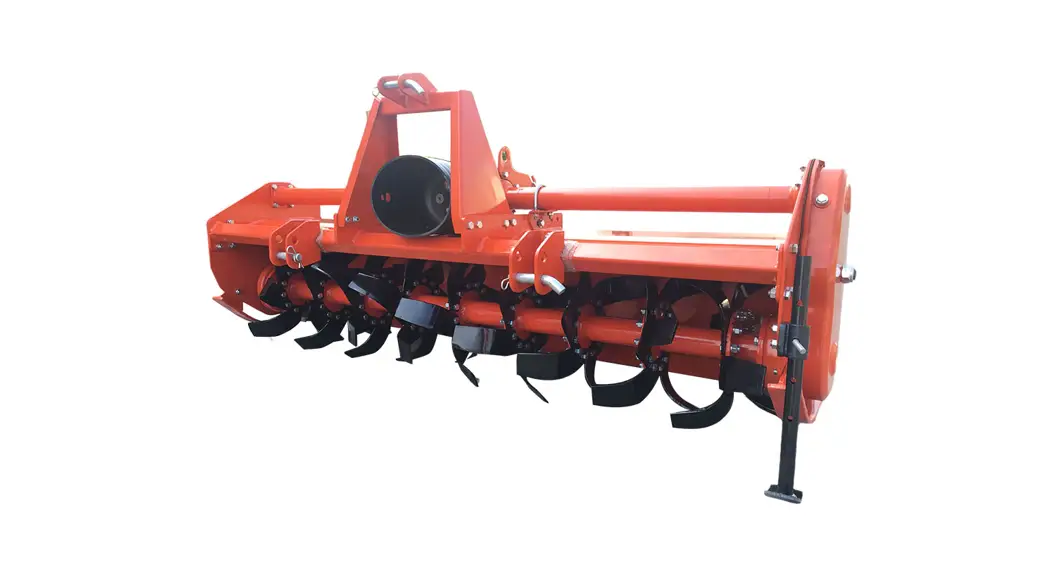

TO THE OWNERS
GENERAL COMMENTS
Congratulations for having this Tractor Rototiller ! Your Tractor Rototiller was carefully designed and manufactured to give you years of dependable service. Your Tractor Rototiller will require some minor maintenance to keep it in top working condition.
Please observe all safety precautions and maintenance procedures as described in this manual.
BEFORE OPERATION
Thoroughly read and understand the instructions given in this manual before operation. Refer to the “Safety Label” section, read all instructions noted on them.
Do not allow anyone to operate his equipment who has not fully read and comprehended this manual and who has not been properly trained in the safe operation of the equipment.
SERVICE
Please remember to use only manufacturer replacement parts. Substitute parts may not meet the standards required for safe, dependable operation.
SAFETY PRECAUTIONS
BEFORE OPERATION
- The operator must read the operation manual carefully before installation, operation or maintenance. Improper operation will cause the machine damage or the operator death.
- Read all the safe signs and safe declarations. Follow all the professional safe terms, local laws or the professional directions.
- Familiar with the Tractor Rototiller about functions, specs and operation. Replace the to-be-damaged parts in time. Make sure all the hydraulic installations and couplings connect firmly, and all the safe signs stick on the suitable positions clearly.
![]() IMPORTANT
IMPORTANT
- Operator should be familiar with all functions of the unit.
- Make sure all guards and shields are in place and secured before operating implement.
- Keep all persons away from equipment and work area.
- Dismounting from a moving unit can cause serious injury or death.
- Keep hands, feet, and clothing away from power-driven parts.
- Detach and store implement in an area where children normally do not play. Secure implement by using blocks and supports.
Always wear proper safety glasses, goggles, or a face shield when driving pins in or out, or when any operation causes dust, flying debris, or any other hazardous material.
Operator Safety
►Wear protective clothing and equipment appropriate for the job. Clothing should be snug fitting without fringes and pull strings to avoid entanglement with moving parts.
►Prolonged exposure to loud noise can cause hearing impairment or hearing loss. Wear suitable hearing protection such as earmuffs or earplugs.
►Operating equipment safely requires the operators all attention, Avoid wearing radio headphones while operating machinery.
Tool Safety
►Inspect entire machine before each use. Replace damaged or worn parts.
►Check for fuel leaks and make sure all fasteners are in place and securely fastened.
Maintenance Safety
►Maintain according to recommended procedures included in this manual.
►Disconnected the spark plug wire before performing maintenance.
►Stop engine before removing fuel cap.
►Use only genuine replacement parts of the engine manufacturer.
![]()
Wear Protective Equipment
►Escaping fluid under pressure can penetrate the skin causing serious injury.
►Avoid the hazard by relieving pressure before disconnecting hydraulic lines or performing work on the system.
►Make sure all hydraulic fluid connections are tight and all hydraulic hoses and lines are in good condition before applying pressure to the system.
►Use a piece of paper or cardboard, NOT BODY PARTS to check for suspected leaks.
►Wear protective gloves and safety glasses or goggles when working with hydraulic systems.
►DO NOT DELAY. If an accident occurs, see a doctor familiar with this type of injury immediately. Any fluid injected into the skin or eyes must be treated within a few hours or gangrene may result.
Transportation and Storing
►Always shut off the fuel valve and engine.
►Always allow engine to cool.
►Store machine and fuel where fuel vapors cannot reach sour combustion like, water heaters, electric motors, switches, furnaces, etc.
►Always secure the machine with tie downs or similar restraints when transporting.
►The machine be stored in a manner that prevents it from falling, rolling or tipping.

ROTOTILLER ASSEMBLES
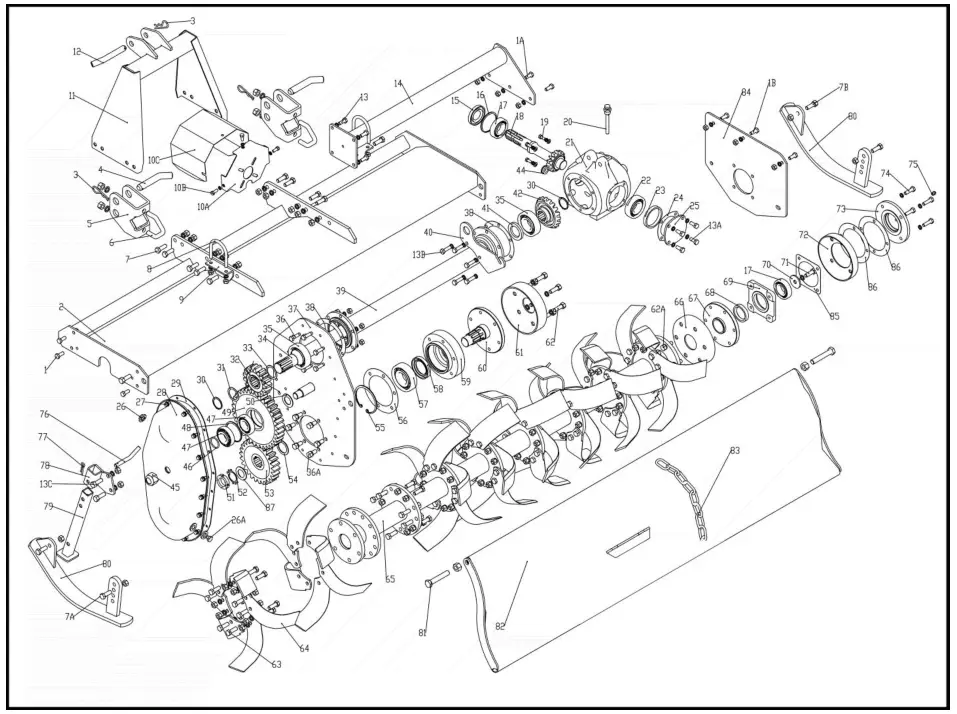
| S/N | PART NO. | PART DESCRIPTION | QTYS | NOTE |
| 1 | Bolt M10*25 | GB/T5783-2000 | 4 | |
| 1A | Bolt M0*25 | GB/T5783-2000 | 3 | |
| 1B | Bolt M10*25 | GB/T5783-2000 | 3 | |
| 2 | Frame Weldment | TS-81-01-01-00 | 1 | |
| 2 | Frame Weldment | TS-74-01-01-00 | 1 | |
| 2 | Frame Weldment | TS-66-01-01-00 | 1 | |
| 2 | Frame Weldment | TS-58-01-01-00 | 1 | |
| 2 | Frame Weldment | TS-50-01-01-00 | 1 | |
| 3 | split pin | TS-66-01-02-03 | 3 |
| S/N | PART NO. | PART DESCRIPTION | QTYS | NOTE |
| 4 | Lower Hitch Block | TS-66-01-02-02 | 2 | |
| 5 | Lower Hitch Connecting Seat Panel | TS-81.01.02. 01-02 | 2 | |
| 5 | Lower suspension connecting plate Weldment | TS-81.01.02. 01 | 2 | |
| 5 | Lower suspension connecting plate Weldment | TS-50/58/66/74 | 2 | |
| 6 | V Bolt | TS-66-01-02-01 | 2 | |
| 7 | Bolt Ml2*35 | GB/T5783-2000 | 10 | |
| 7A | Bolt Ml2*35 | GB/T5783-2000 | 2 | |
| 7B | Bolt M2*30 | GB/T5783-2000 | 2 | |
| 8 | U Bolt | TS-66-03-01 | 2 | |
| 9 | Support – Drive shaft housing | TS-66-03-02 | 2 | |
| 10A | Support – Gearbox Shielding | TS-66-02-02-02 | 1 | |
| 10B | Bolt | GB/T5783-2000 | 3 | |
| 10C | Gearbox Shield | TS-66-02-02-01 | 1 | |
| 11 | A Frame | TS-66-01-03-01-00 | 1 | |
| 12 | Top Hitch Pin | TS-66-01-03-01 | 1 | |
| 13 | Bolt Ml0*20 | GB/T5783-2000 | 4 | |
| 13A | Bolt M10*25 | GB/T5783-2000 | 4 | |
| 13B | Bolt M10*25(4)M10*30 (2) | GB/T5783-2000 | 6 | |
| 13C | Bolt M10*25 | GB/T5783-2000 | 2 | |
| 14 | Gearbox Support Tube | TS-81-04-00 | 1 |
| S/N | PART NO. | PART DESCRIPTION | QTYS | NOTE |
| 14 | Gearbox Support Tube | TS-74-04-00 | 1 | |
| 14 | Gearbox Support Tube | TS-66-04-00 | 1 | |
| 14 | Gearbox Support Tube | TS-50/58-04-00 | 1 | |
| 15 | Floating Seal 72*35*10 | HG4-692-67 | 1 | |
| 16 | Snap Ring 072 | GB/T893. 1-1986 | 1 | |
| 17 | Bearing 6207 | GB/T276-1994 | 2 | |
| 18 | Pinion Gear | TS-66-02-05 | 1 | |
| 19 | Bolt M8*16 | GB/T5783-2000 | 4 | |
| 20 | Gearbox Oil Plug (Dip Stick) | 1 | ||
| 21 | Housing – Gearbox | TS-66-02-01 | 1 | |
| 22 | Bearing 6307 | GB/T276-1994 | 1 | |
| 23 | Spacer | TS-66-02-04 | 1 | |
| 24 | Gasket Bearing Cover (102*^75*0. 5) | TS-66-02-03 | 1 | |
| 25 | Bearing Cover | TS-66-02-02 | 1 | |
| 26 | Breather Cap 5 | 1 | ||
| 26A | Add Oil Bolt Ml6*1. 5 | 1 | ||
| 27 | Bolt M8*25 | GB/T5783-2000 | 16 | |
| 28 | Side Drive Cover | TS-66-08-01-00 | 1 | |
| 29 | Gasket – Gear/Chain Cover | TS-66-08-01 | 1 | |
| 30 | Snap Ring Ext. | GB/T894. 2-1986 | 2 | |
| 31 | Output Gear Shim | |||
| 32 | Input Gear | TS-66-02-09 | 1 | |
| 33 | Gasket-Driving Gear | TS-66-02-08 | 1 | |
| 34 | Drive Shaft | TS-81-02-10 | 1 | |
| 34 | Drive Shaft | TS-74-02-10 | 1 | |
| 34 | Drive Shaft | TS-66-02-10 | 1 | |
| 34 | Drive Shaft | TS-58-02-10 | 1 | |
| 34 | Drive Shaft | TS-50-02-10 | 1 | |
| 35 | Bearing 6308 | GB/T276-1994 | 2 |
| S/N | PART NO. | PART DESCRIPTION | QTYS | NOTE |
| 36 | Bolt Ml0*30 | GB/T5783-2000 | 6 | |
| 36A | Bolt Ml2*25 | GB/T5783-2000 | 6 | |
| 37 | Side Panel – Left | TS-66-01-04-00 | 1 | |
| 38 | Gasket – Drive shaft (151*136*0. 5) | TS-66-02-07 | 2 | |
| 39 | Drive Shaft Tube Housing | TS-81-02-01-00 | 1 | |
| 39 | Drive Shaft Tube Housing | TS-74-02-01-00 | 1 | |
| 39 | Drive Shaft Tube Housing | TS-66-02-01-00 | 1 | |
| 39 | Drive Shaft Tube Housing | TS-58-02-01-00 | 1 | |
| 39 | Drive Shaft Tube Housing | TS-50-02-01-00 | 1 | |
| 40 | Lifting Hook | TS-66-02-11 | 1 | |
| 41 | Oil Seal – Drive shaft tube housing40*65*8 | HG4-692-67 | 1 | |
| 42 | Ring Gear | TS-66-02-06 | 1 | |
| 44 | Drain Plug | 1 | ||
| 45 | Lock Nut M24*l. 5 | 1 | ||
| 46 | O-Ring023. 6*3. 55 | GB/T3452. 1-2005 | 1 | |
| 47 | Bearing 30306 | GB/T297-1994 | 2 | |
| 48 | Snap Ring 072 | GB/T893. 1-1986 | 1 | |
| 49 | Idler Gear | TS-66-08-02 | 1 | |
| 50 | Plain Washers 030 | 1 | ||
| 51 | Lock Nut M35*1.5 | 1 | ||
| 52 | Retaining Washer 035 | GB/T858-1988 | 1 | |
| 53 | Bottom Gear | TS-66-08-04 | 1 | |
| 54 | Shim | TS-66-08-06 | 1 | |
| 55 | Snap Ring 0100 | GB/T893. 1-1986 | 1 | |
| 56 | Gasket – Rotor(168* 115*0. 5) | TS-66-08-08 | 1 | |
| 57 | Bearing 6309 | GB/T276-1994 | 1 | |
| 58 | Oil Seal 80*50*12 | HG4-692-67 | 1 | |
| 59 | Bearing Support – Left Side | TS-66-08-05 | 1 | |
| 60 | Rotor Support shaft | TS-66-08-07 | 1 |
| S/N | PART NO. | PART DESCRIPTION | QTYS | NOTE |
| 61 | Rotor Shield-Left | TS-66-08-09 | 1 | |
| 62 | Bolt M12*35 | GB/T5783-2000 | 6 | |
| 62A | Bolt M12*30 | GB/T5783-2000 | 6 | |
| 63 | Bolt M2*1. 25*35 | GB/T5786-2000 | 96 | |
| 64 | Tiller Blade | 2-012.4 pitch 42. 4 | 48 | |
| 65 | Rotor Weldment | TS-81-09-01-01-00 | 1 | |
| 65 | Rotor Weldment | TS-74-09-01-01-00 | 1 | |
| 65 | Rotor Weldment | TS-66-09-01-01-00 | 1 | |
| 65 | Rotor Weldment | TS-58-09-01-01-00 | 1 | |
| 65 | Rotor Weldment | TS-50-09-01-01-00 | 1 | |
| 66 | Dust Cover-Right | TS-66-09-01 | 1 | |
| 67 | Rotor Support shaft – Right side | TS-66-09-03 | 1 | |
| 68 | Oil Seal 62*45*12 | HG4-692-67 | 1 | |
| 69 | Bearing Support | TS-66-09-04 | 1 | |
| 70 | Retaining Washer | TS-66-09-08 | 1 | |
| 71 | Bolt 2*20 | GB/T5783-2000 | 1 | |
| 72 | Dust Cover-Right | TS-66-09-02 | 1 | |
| 73 | End Cap – Rotor Right side | TS-66-09-07 | 1 | |
| 74 | Bolt Ml 0*35 | GB/T5783-2000 | 4 | |
| 75 | Grease Fitting Ml 0*1 | 1 | ||
| 76 | Pin – Stand | TS-66-05-01 | 1 | |
| 77 | R-Clip – Stand | TS-66-05-02 | 1 | |
| 78 | Stand Bracket | TS-66-05-02-00 | 1 | |
| 79 | Stand Leg | TS-66-05-01-00 | 1 | |
| 80 | Skid Weldment | TS-66-06-00 | 1 | |
| 81 | Bolt Ml 6*90 | 2 | ||
| 82 | Tailgate | TS-81-07-01-00 | 1 |
| S/N | PART NO. | PART DESCRIPTION | QTYS | NOTE |
| 82 | Tailgate | TS-74-07-01-00 | 1 | |
| 82 | Tailgate | TS-66-07-01-00 | 1 | |
| 82 | Tailgate | TS-58-07-01-00 | 1 | |
| 82 | Tailgate | TS-50-07-01-00 | 1 | |
| 83 | Tailgate Chain assembly | TS-66-07-02-01 | 1 | |
| 84 | Side Panel – Right | TS-66-01-01 | 1 | |
| 85 | Gasket 2 (0119*0*95*0. 5) | TS-66-09-06 | 1 | |
| 86 | Gasket 1( 150* 108*0. 5) | TS-66-09-05 | 1 | |
| 87 | Shim 2 | T*.04-02 | 1 |
DRIVE SHAFT ASSEMBLES
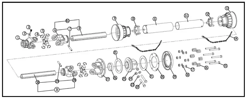
| S/N | PART NO. | PART DESCRIPTION | QTYS | NOTE |
| 1 | 6 Spline Yoke for tractor side | 1 | ||
| 2 | Pin Ф13*47 | 1 | ||
| 3 | Spring Ф0.9*25 | 1 | ||
| 4 | Circlips Ф27 | 8 | ||
| 5 | U.joint 27×74.5 | 2 | ||
| 6 | Outer tube yoke | 1 | ||
| 7 | pin Ф10*65 | 1 | ||
| 8 | Triangle Outer tube | 1 | ||
| 9 | Outer shield cone | 1 | ||
| 10 | Outer shield bearing | 1 | ||
| 11 | Outer shield tube | 1 | ||
| 11 | Inner shield tube | 1 | ||
| 12 | Inner shield bearing | 1 | ||
| 13 | Inner shield cone | 1 | ||
| 14 | Safety Chain | 2 | ||
| 15 | Bolt M10*95 | 6 | ||
| 16 | Spring Ф6.5*46 | 6 | ||
| 17 | Washer Ф10 | 6 | ||
| 18 | Nylon self-locking nut M10 | 6 |
| S/N | PART NO. | PART DESCRIPTION | QTYS | NOTE |
| 19 | blind flange | 1 | ||
| 20 | driven plate | 1 | ||
| 21 | Friction disk | 2 | ||
| 22 | Bolt M12*70 | 2 | ||
| 23 | Washer Ф12 | 2 | ||
| 24 | Nylon self-locking nut M12 | 2 | ||
| 25 | flange | 1 | ||
| 26 | Nylon bushing | 1 | ||
| 27 | Clutch Yoke | 1 | ||
| 28 | Inner tube Yoke | 1 | ||
| 29 | Pin Ф10X60 | 1 | ||
| 30 | Triangle Inner tube | 1 |
OPERATION INSTRUCTIONS
![]() Check the unit before attaching the rotary tiller to the tractor to ensure there is oil in the top and side gear box. See Maintenance section for lubricant specifications.
Check the unit before attaching the rotary tiller to the tractor to ensure there is oil in the top and side gear box. See Maintenance section for lubricant specifications.
Check the oil grease points before starting operation
Oil level: Top gearbox 1 1/2” from the end of the dip stick. When sitting slightly tilted forward, oil should at the bottom of the fill plug on the side gearbox cover.
Grease: Right Rotor bearing, PTO shaft Cross & Bearings
Attaching to the tractor
- With the Rotary Tiller on a level surface, back the Cat. 1 tractor so the tractor lift arms are even with the unit’s lower hitch pins. Lower or raise the tractor hitch arms until the 7/8” bushing in the arm is inside the clevis of lower hitch points. Be sure nothing is between the tractor and the tiller before backing up.
- Insert the lower hitch pin through the lower hitch blocks and the tractor arm. The YCT series tillers have adjustable lower hitch blocks that can be slide to facilitate usage on larger tractors.
- Secure the lift arm in place by using a 7/16” lynch pin or other fastener.
- Repeat with the other arm.
- Connect the driveline to the tractor’s PTO output shaft. Secure it in place.
- Connect the tractor top link to the upper hitch point of the rotary tiller.
- Start the tractor and slowly raise the tiller. Check for drawbar interference. Be sure that the PTO driveline does not bottom out when lifting the machine to it’s maximum height. If it does appear that it could bottom out, it is necessary to shorten the PTO driveline. (See Shortening a PTO Driveline section). Ensure that in the working position there is an overlap of a minimum of 1/3 the length of each profile.
Shortening a PTO Driveline
- With the implement attached to the tractor’s three point hitch, and the PTO driveline not installed, separate the PTO driveline. Attach the implement end to the implement and the other end to the tractor PTO input shaft.
- Raise the implement by using the tractor’s hydraulic 3-point hitch to it’s maximum lift height.
- Hold the half shafts next to each other and mark them so each end is approximately ½” from hitting the end of the telescopic profiles.
- Shorten the inner and out guard tubes equally.
- Shorten the inner and outer profiles by the same length as the guard tubes. Using a rat tail file, round off all sharp edges and burrs. Grease the telescopic profile generously before reassembling.
![]() Do not shorten too much, the proper overlap is a minimum of 1/3 the length of each profile.
Do not shorten too much, the proper overlap is a minimum of 1/3 the length of each profile.![]() Caution: Slip Clutches may get hot. Do Not Touch. Keep the slip clutch area clear of an material that may catch fire.
Caution: Slip Clutches may get hot. Do Not Touch. Keep the slip clutch area clear of an material that may catch fire.
Slip clutches have adjustable torque settings. The torque setting varies with the different compression of each spring. All the springs should have an equal amount of compression.
IMPORTANT: Do not over-tighten the compression nuts as this may impair performance or cause premature wearing of the slip clutch.
Slip Clutch adjustments
- Using a marker, scribe a line across the exposed edges of the clutch plate and friction discs.
- Back off compression nuts to free friction discs by turning each nut exactly 2 revolutions.
- Start the tractor and run the driveline at a low idle to slip the friction discs. This will remove the dirt, corrosion and surface floss from the clutch plate faces.
- Disengage PTO, shut down the tractor and wait for all components to come to a complete stop.
- Inspect the clutch and ensure that the scribed markings on the disc and plates have changed position. If any two marks are still aligned, this is an indication that these discs have not slipped. It may need to completely disassemble the clutch to free them up.
- After ensuring all discs are free, tighten the compression nuts, uniformly, exactly 2 revolutions to resent the clutch original pressure.
Working Depth Adjustment
The working depth is controlled by raising or lowering the side skids. If the skids are raised, the working depth increases. By lowering the skids, the tilling depth with decrease.
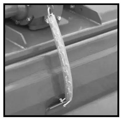
Tailgate adjustment
The tailgate can be adjusted to help smooth and compact the tilled ground. Release the chain and secure to the desired height.
Start up
After making the necessary adjustments, lower the rotary tiller until the blades are a couple of inches from the ground. Engage the PTO and slowly lower the tiller to begin working.
Removal and Storage
After finishing, remove the rotary tiller from the tractor.
- Put the PTO driveline in a safe location to avoid damage.
- Clean and dry the equipment.
- Replace any damaged or worn parts.
- Check all bolts and nuts for tightness.
- Lubricate and protect the machine from the elements.
![]()


