MokerLink POE-G042GSO Rainproof PoE Switch
About guide
This guide provides instructions to install the Switch.
![]() Note: The model you have purchased may appear slightly different from the illustrations shown in the document. Refer to the Product Instruction and Technical Specification sections for detailed information about your switch, its components, network connections, and technical specifications.
Note: The model you have purchased may appear slightly different from the illustrations shown in the document. Refer to the Product Instruction and Technical Specification sections for detailed information about your switch, its components, network connections, and technical specifications.
This guide mainly divided into 4 parts:
- About guide: Terminology/Copyright and statement
- Product introduction: functional overview and introduction of panel definitions
- Hardware installation: step by step hardware installation process
- Technical specifications
Terminology
![]() Note: indicates important information that helps a betteruse of the device.
Note: indicates important information that helps a betteruse of the device.![]() Warning: indicates potential property damage or personal injury.
Warning: indicates potential property damage or personal injury.
Copyright and statement
Without the express written permission of the company, no unit or individual is allowed to imitate, copy, transcribe or translate part or all of the contents of this book without authorization.
The pictures and data shown in this guide are for reference only, subject to change without notice.
Products Introduction
Thanks for purchasing the Switch products.
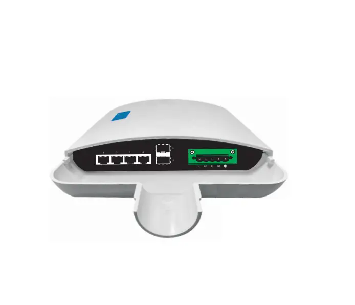
This product is an outdoor rainproof full Gigabit PoE switch. Equipped with 4 10110011 000Mbps RJ45 PoE ports and 2 Gigabit SFP ports, which can meet the full speed forwarding of the ports. This product adopts ABS plastic outdoor rainproof shell for, Holding pole installation. Excellent performance can help you widely used in wireless, surveillance and other fields.
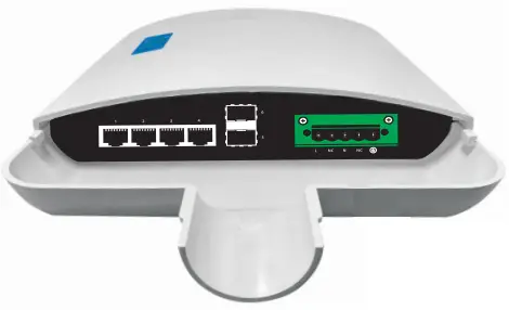
Front Panel
LED Lamp
Power LED: The Power LED lights up when the switch is connected to a power source.
Link/Act indicator: the light indicates the network connection through the corresponding port. Flicker indicates that the switch is sending or receiving data PoE indicator: constant brightness indicates that the PD device is connected to the corresponding port, and extinguished indicates that the port is not powered or no PD device is found .
Rear Panel
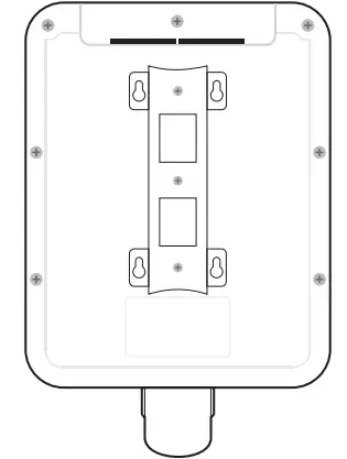
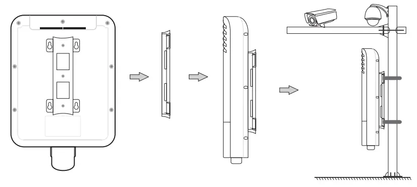
The back is composed of mounting brackets, which can be used for wall -mounting and pole -mounting.
Hardware installation
This chapter provides unpacking and installation information for the Switch.
open a seal
Open the shipping carton and carefully unpack its contents. Please consult the packing list located in the User Manual to make sure all items are present and undamaged. If any item is missing or damaged, please contact the local reseller for replacement.
- → Switch 1 pcs
- → User’s manual 1 pcs
- → Power cord 1pcs
Switch installation
For safe switch installation and operation, it is recommended that you:
- → Visually inspect the power cord to see that it is secured fully to the AC power connector .
- → Make sure that there is proper heat dissipation and adequate ventilation around the switch .
- → Do not place heavy objects on the switch.
Holding pole installation
Connect power supply
The power connection uses a quick-plug terminal block connector. It is recommended that the user use a cable with a current capacity of more than 6A.
![]() Warning: When connecting to the power supply system, please pay attention to the polarity marks of the interface avoid connection errors.
Warning: When connecting to the power supply system, please pay attention to the polarity marks of the interface avoid connection errors.
The terminal block connector the of is used for power input. Please follow the steps below to insert the power wire:
- Insert two power lines into the hole at the end side of the connection.
- tighten the screw above the connection end clockwise with a screwdriver, for preventing the power line from loosing.
- The other end of the power line is connected to the power supply system.

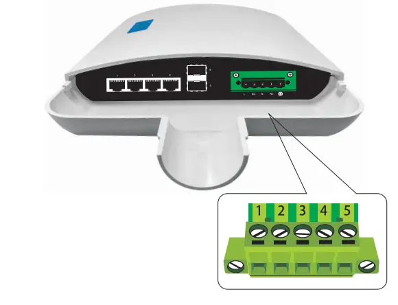
| 1 | 2 | 3 | 4 | 5 |
| L | NC | N | NC | Ground |
The wire gauge for the terminal block should be in the range between 12-24AWG.
Technical specifications
| Project | Describe |
| Attributes | |
| Networking Interfaces | 4 x 10/100/1000Mbps RJ45 Ethernet Ports 2 x 1Gbps SFP Ports |
| LED Indicators | Power, Link/Act, PoE |
| Performance | |
| Switching Capacity | 12 Gbps |
| Forwarding Capacity | 8.93 Mpps |
| Forwarding Mode | Store and Forward |
| Packet Buffer Memory | 2 Mbit |
| MAC Address Table | BK |
| Physical | |
| Dimensions | 295x206x50mm |
| Operating Temperature | 0 to 40°C |
| Storage Temperature | -10 to 75°C |
| Operating Humidity | 5 to 95% Noncondensing |
| Power Method | 100- 240VAC, 50/60Hz |
| Power Consumption | SW |
| Casing | ABS plastic |
| Installation | Holding pole installation |
| Power over Ethernet | |
| PoE Ports | 4 |
| PoE Standard | IEEE802.3af / IEEE802.3at |
| PoE Power Budget | 65W |
| Max. PoE Wattage per Port | 30W |
| PoE Voltage | 52V |
| PoE Pin Assignment | V- (RJ45 Pin1,2), V+ (RJ45 Pin 3,6) |

Rm 10, 13/F,Main Building 7,Changhang Lanjing International,
No.116 Gaoxin Ave.,Hongshan Dist.,Wuhan,China
http://www.mokerlink.com
[email protected]