Wi-Tek WI-PS302GF-I Unmanaged Industrial Hardened PoE Switch Instruction Manual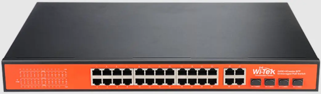
Package Content
1 x Switch
1 x Installation Guide
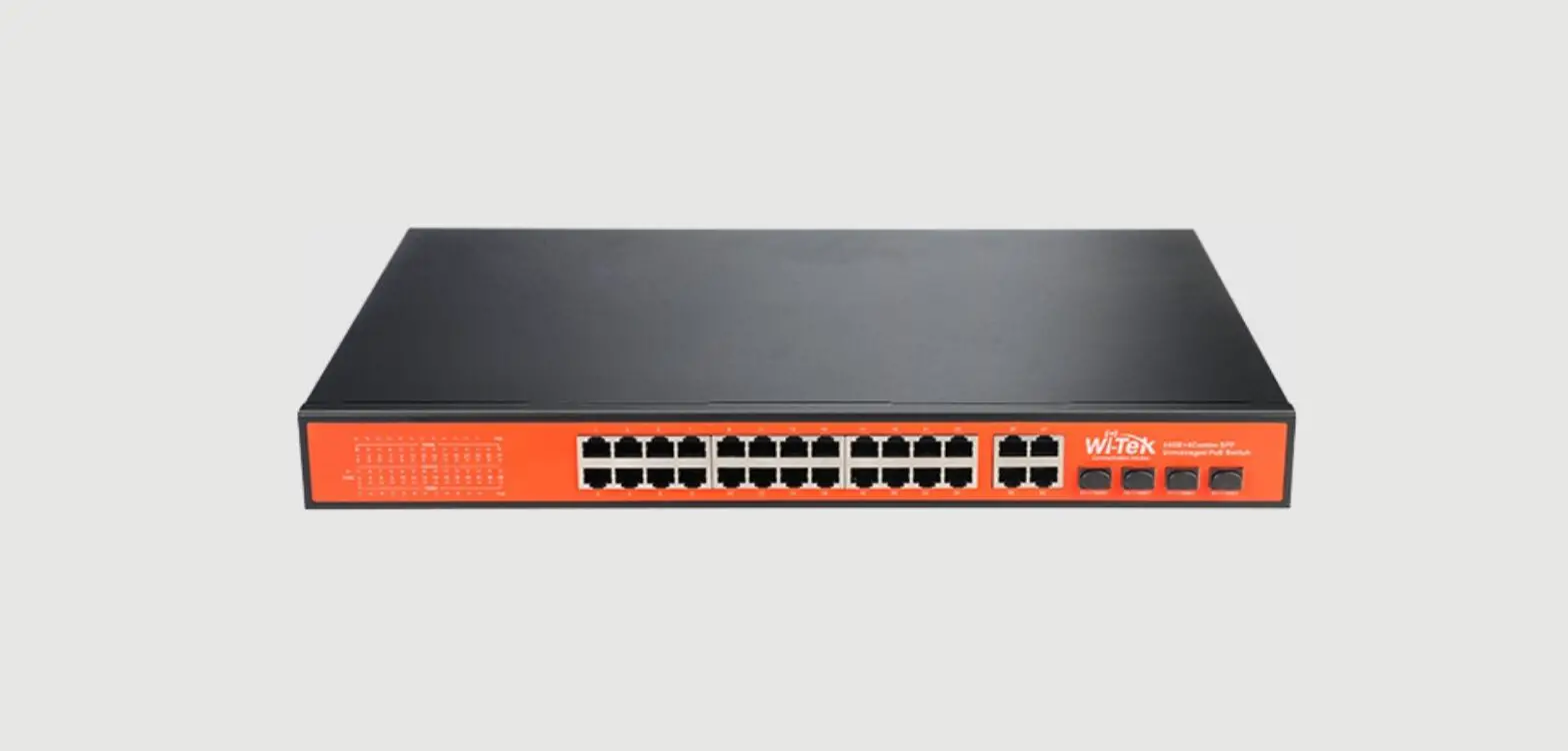
Interface and LED Indicator
WI-PS302GF-I
| Interfaces | |
| Ethernet Port | 1*10/100/1000 Base-T PoE+ + RJ-45 |
| Fiber Port | 1*1000 Base-X SFP slot |
| DIP Switch Mode | |
| 1. Fiber Watchdog | Monitor the fiber connection status, and if no data is transmitted, the port will restart automatically. |
| 2. PoE Watchdog | All PoE ports enable PoE watchdog function, which can detect and reboot the offline compliant PoE powered devices. |
| 3. Extend Mode | The transmission distance of PoE port can be up to 250m, but the rate is limited to 10Mbps. |
| 4. 60W PoE Mode | Enable this function, the PoE port will output 60W PoE power. Disable this function, the PoE port output 802.3at 30W PoE power. |
| LED Indicators | |
| PW (Power indicator) | Off: the device is power off or failed On: the device power on is normal |
| V1/V2/V3(Input power indicator) | Off: No power supplyOn: Power is supplying via V1/V2/V3 DC connector |
| Link Indicator | Off: ports link down On: ports link up Blinking: data on TX/RX |
| EX Indicator | Off: Extend mode is disabled. On: Extend mode is enabled. |
| SFP Indicator | Off: ports link down Green On: ports link up Blinking: data on TX/RX |
WI-PS306GF-I
| Interfaces | |
| Ethernet Port | 4*10/100/1000 Base-T PoE RJ-45 port Ports 1-2 : 24V Passive / 48V 802.3 af/at PoE Ports 3-4: 802.3 af/at/bt 60W |
| Fiber Port | 2*1000 Base-X SFP |
| DIP Switch Mode | |
| 1. FWD | Monitor the fiber connection status, and if no data is transmitted, the port will restart automatically. |
| 2. PWD | All PoE ports enable PoE watchdog function, which can detect and reboot the offline compliant PoE powered devices. |
| 3. Extend | The transmission distance of PoE port can be up to 250m, but the rate is limited to 10Mbps. |
| 4. VLAN | All downlink ports are isolated from each other, but can communicate with uplink ports. |
| LED Indicators | |
| PWR (Power indicator) | Off: the device is power off or failed On: the device power on is normal |
| P1/P2(Input power indicator) | Off: No power supplyOn: Power is supplying via P1/P2 DC connector |
| Link Indicator | Off: ports link down On: ports link up Blinking: data on TX/RX |
| PoE Indicator | Off: PoE not working On: PoE working |
| 5/6 (SFP Indicator) | Off: ports link down On: ports link up Blinking: data on TX/RX |
| PoE Max | On: PoE power full load |
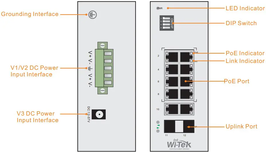
WI-PS310GF-I
| Interfaces | |
| PoE Port | 8*10/100/1000 Base-T PoE RJ-45 port Ports 1-2: 24V Passive / 48V 802.3 af/at PoE Ports 3-4: 802.3 af/at/bt 60WPorts 5-8: 802.3 af/at PoE |
| Uplink Port | 2*1000 Combo Base-X SFP |
| DIP Switch Mode | |
| 1. 24/48 | PoE output voltage adjustment DIP switch for port 1. |
| 2. 24/48 | PoE output voltage adjustment DIP switch for port 2. |
| 3. Watchdog | All PoE ports enable PoE watchdog function, which can detect and reboot the offline compliant PoE powered devices. |
| 4. Extend | The transmission distance of PoE port can be up to 250m, but the rate is limited to 10Mbps. |
| 4. VLAN | The transmission distance of PoE port can be up to 250m, but the rate is limited to 10Mbps. |
| LED Indicators | |
| PWR (Power indicator) | Off: the device is power off or failed On: the device power on is normal |
| P1/P2(Input power indicator) | Off: No power supplyOn: Power is supplying via P1/P2 DC connector |
| Link Indicator | Off: ports link down On: ports link up Blinking: data on TX/RX |
| PoE Indicator | Off: PoE not working On: PoE working |
| 9/10 (SFP Indicator) | Off: ports link down On: ports link up Blinking: data on TX/RX |
| PoE Max | On: PoE power full load |
WI-PS305G-I-DC
| Interfaces | |
| PoE Port | 4*10/100/1000 Base-T PoE RJ-45 port Ports 1-4: 802.3 af/at PoE |
| Uplink Port | 1*10/100/1000 Base-T RJ-45 port |
| DIP Switch Mode | |
| 1. PoE Watchdog | PoE watchdog, all PoE ports enable PoE watchdog function, which can detect and reboot the offline compliant PoE powered devices. |
| 2. Port VLAN | All downlink ports are isolated from each other, but can communicate with uplink ports. |
| 3. EX_1-2 | The transmission distance of port 1-2 can be up to 250m, but the rate is limited to 10Mbps. |
| 4. EX_1-4 | The transmission distance of port 1-4 can be up to 250m, but the rate is limited to 10Mbps. |
| LED Indicators | |
| PWR (Power indicator) | Off: the device is power off or failed On: the device power on is normal |
| P1/P2(Input power indicator) | Off: No power supplyOn: Power is supplying via V1/V2 DC connector |
| Link Indicator | Off: ports link down On: ports link up Blinking: data on TX/RX |
| PoE Indicator | Off: PoE not working On: PoE working |
WI-PS206-I
| Interfaces | |
| Ethernet Port | 4*10/100 Base-TX PoE RJ-45 ports Ports 1 : 802.3 af/at/bt 90WPorts 2-4: 802.3 af/at PoE |
| Fiber Port | 2*10/100 Base-TX RJ-45 ports |
| DIP Switch Mode | |
| 1. PoE Watchdog | PoE watchdog, all PoE ports enable PoE watchdog function, which can detect and reboot the offline compliant PoE powered devices. |
| 2. EX_1-2 | The transmission distance of port 1-2 can be up to 250m, but the rate is limited to 10Mbps. |
| 3. EX_1-4 | The transmission distance of port 1-4 can be up to 250m, but the rate is limited to 10Mbps. |
| 4. VLAN | All downlink ports are isolated from each other, but can communicate with uplink ports. |
| LED Indicators | |
| PW (Power indicator) | Off: the device is power off or failed On: the device power on is normal |
| V1/V2/V3(Input power indicator) | Off: No power supplyOn: Power is supplying via V1/V2/V3 DC connector |
| Link Indicator | Off: ports link down On: ports link up Blinking: data on TX/RX |
| PoE Indicator | Off: PoE not working On: PoE working |
| VLAN | Off: VLAN mode is disable. On: VLAN mode is enable. |
| Extend | Off: Extend mode is disable. On: Extend mode is enable. |
WI-PS208-I
| Interfaces | |
| PoE Port | 8*10/100 Base-TX PoE RJ-45 ports Ports 1-2 : 802.3 af/at/bt 90WPorts 3-8: 802.3 af/at PoE |
| DIP Switch Mode | |
| 1.PoE Watchdog | PoE watchdog, all PoE ports enable PoE watchdog function, which can detect and reboot the offline compliant PoE powered devices. |
| 2. EX_1-4 | The transmission distance of port 1-4 can be up to 250m, but the rate is limited to 10Mbps. |
| 3. EX_1-6 | The transmission distance of port 1-6 can be up to 250m, but the rate is limited to 10Mbps. |
| 4. VLAN | All downlink ports are isolated from each other, but can communicate with uplink ports. |
| LED Indicators | |
| PW (Power indicator) | Off: the device is power off or failed On: the device power on is normal |
| V1/V2/V3(Input power indicator) | Off: No power supplyOn: Power is supplying via V1/V2/V3 DC connector |
| Link Indicator | Off: ports link down On: ports link up Blinking: data on TX/RX |
| PoE Indicator | Off: PoE not working On: PoE working |
| VLAN | Off: VLAN mode is disable. On: VLAN mode is enable. |
| Extend | Off: Extend mode is disable. On: Extend mode is enable. |
WI-PS206GF-I
| Interfaces | |
| PoE Port | 4*10/100 Base-TX PoE RJ-45 ports Ports 1-4: 802.3 af/at PoE |
| Uplink Port | 1*1000 Base-X SFP slot 1*10/100/1000 Base-T RJ-45 port |
| DIP Switch Mode | |
| 1. 250m | The transmission distance of port 1-4 can be up to 250m, but the rate is limited to 10Mbps. |
| 2. VLAN | All downlink ports are isolated from each other, but can communicate with uplink ports. |
| 3. Watchdog | PoE watchdog, all PoE ports enable PoE watchdog function, which can detect and reboot the offline compliant PoE powered devices. |
| 4. Priority | Port PoE power supply priorities are in descending order. |
| LED Indicators | |
| PWR (Power indicator) | Off: the device is power off or failed On: the device power on is normal |
| Link Indicator | Off: ports link down On: ports link up Blinking: data on TX/RX |
| PoE Indicator | Off: PoE not working On: PoE working |
| 6 (SFP Indicator) | Off: ports link down On: ports link up Blinking: data on TX/RX |
WI-PS212GF-I
| Interfaces | |
| PoE Port | 8*10/100 Base-TX PoE RJ-45 ports Ports 1-8: 802.3 af/at PoE |
| Uplink Port | 2*1000 Base-X SFP slot 2*10/100/1000 Base-T RJ-45 port |
| DIP Switch Mode | |
| 1.250m | The transmission distance of port 1-4 can be up to 250m, but the rate is limited to 10Mbps. |
| 2.VLAN | All downlink ports are isolated from each other, but can communicate with uplink ports. |
| 3.Watchdog | PoE watchdog, all PoE ports enable PoE watchdog function, which can detect and reboot the offline compliant PoE powered devices. |
| 4.Priority | Port PoE power supply priorities are in descending order. |
| LED Indicators | |
| PWR (Power indicator) | Off: the device is power off or failed On: the device power on is normal |
| Link Indicator | Off: ports link down On: ports link up Blinking: data on TX/RX |
| PoE Indicator | Off: PoE not working On: PoE working |
| 11/12 (SFP Indicator) | Off: ports link down On: ports link up Blinking: data on TX/RX |
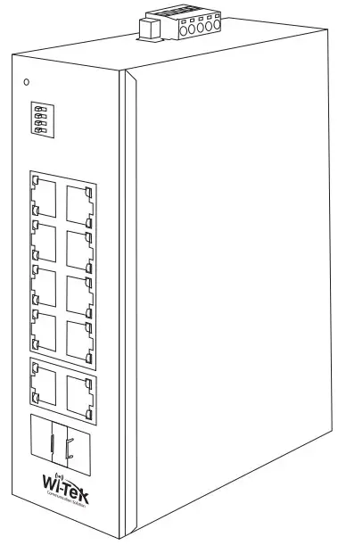
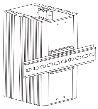
DIN-rail Installation
Please follow the steps below.
| Step 1: Install the switch to the DIN rail. Accessories | |
 | Null |
DC Power Cable Connection

This switch can work with 37~57V DC power, the DC power connection processes are as follows.
- Before installation, ensure that the device is disconnected from the power supply.
- Connect one end of the protective grounding cable to the grounding screw on the side panel of the device, and the other end is well grounded nearby.
- Connect the positive and negative wires of DC power separately to the “+” and “-” power terminal of 48~57V power 1 or 37~57V power 2 on the switch as following figure, using screw driver to screw stably.
- The redundant power can be both connected with the DC power, so that one power supply can still work in case the other one fails.
- Turn on the DC power, and check if power supply indicator of power 1 or power 2 turns on, whic
Note: For WI-PS206GF-I and WI-PS212GF-I, V1 and V2 DC interface cannot be connected to the power supply at the same time.
Warranty Card
| Username | |
| Address | |
| Telephone No. | |
| Purchase Shop | |
| Purchase Address | |
| Product Model No. | |
| Purchase Time | |
| Serial No. | |
| Dealer Signature |
- If the product defects within three months after purchase, we will provide you a new product of the same model.
- If the product defects within the three-year warranty period, we will provide the professional maintenance service.
- Proof of purchase and a complete product serial number are required to receive any services guaranteed as part of the limited warranty.
- Any other defects that are not caused by workmanship or product quality, such as
natural disaster, water damage, extreme thermal or environmental conditions. sticker damaged, warranty card losing will disqualify the product from limited warranty.
Technical Support
Cloud Managemen
Company Website
Wireless-Tek Technology Limited
Address: Room 402 4F, BiaoFan Technology Building, Bao’An
Avenue, FuYong Town, Bao’An district, ShenZhen
Website:www.wireless-tek.com
Tel:86-0755-32811290
Email:[email protected]
Technical Support:[email protected]