![]()
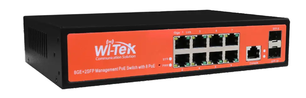
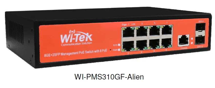
Wi-Tek WI-PMS310GF-Alien Gigabit L2 Managed PoE Switch

Introduction
The WI-PMS310GF-Alien is an Auto-PoE, Managed, Layer 2 (L2), POE (24 & 48V) IP Switch, with Gigabit Ethernet (GbE), Small Form-factor Pluggable (SFP), and serial Console interfaces.
This document supplements the Wi-TeK Managed Industrial PoE Switch User Manual, available for download from:
http://www.wireless-tek.com/Uploads/download/1583371174.pdf
Package Contents
System Requirements
Web Browser: e.g. Mozilla Firefox, Google Chrome, Safari, Microsoft Edge, or Microsoft Internet Explorer.
LEDs
System LEDs
| LED | State | Status |
| SYS | Blinking (slow) | Normal Operation |
| Flashing (Fast) | Initializing (boot up) | |
| PWR | On | Steady on if power applied |
RJ45 LEDs
| LED | State | Status |
| PoE | Off | No Power applied |
| Green | 48 V PoE applied | |
| Orange | 24 V PoE applied | |
| Link | Green | 10/100/1000 Mbps connection. Flashes with activity. |
| Off | No Ethernet connection |
SFP LEDs
| LED | State | Status | |
| 9 | Off | No link | |
| 10 | |||
| Green | Link established at 1000 Mbps (1 Gbps) | ||
| Flashing Indicates Activity |
Front Panel
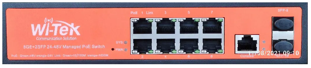
| Port | Description |
| Note | Active PoE means that PoE voltage is applied only if a device is connected. |
| RJ45 1-8 | LAN: 10/100/1000 bps Ethernet connection PoE Out. 2-Pair, Pins: 48V=1,2(+) 3,6 (-), 24V=4,5(+) 7,8 (-) Software selectable: · Off · 24 V Active · 48 V Active 802.3af 15 W max · 48 V Active 803.3at 30 W max · Auto Active, Auto selection Off/24/48V PoE · 24V Forced On · 48V Forced On |
| SFP 9-10 | Hot-swappable Small Form-factor Pluggable (SFP) ports supporting 1 Gbps connections. |
| Console | This port is compatible with Cisco part number 72-3383-01 (Console Cable). The serial settings are: Baud rate: 38400 Data bits: 8 Stop bits: 1 Parity: None Flow control: None |
Configuration
This section covers some tasks that are not fully covered in the User Manual (see section Introduction, page 3).
Accessing the Configuration Interface
There are two configuration options:
- Graphical User Interface (GUI), using an Ethernet connection.
- Command Line Interface (CLI), using a console cable.
Graphical User Interface
For full details, download this document: http://www.wireless-tek.com/Uploads/download/1583371174.pdf When in Factory Reset state, the Switch is set to use the default IP address of 192.168.0.1.
- Make sure that your host system is connected via Ethernet to the Switch.
- Configure the Ethernet adapter on your host system with a static IP address in the 192.168.0.x subnet.
e. g. 192.168.0.10 - Launch your web browser and type http://192.168.0.1 in the address field. Press enter (PC) or return (Mac).


Enter the login credentials.
The default credentials are:
Username: admin
Password: admin 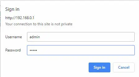
Command Line Interface
For full details, download these documents:
- https://ubwh.com.au/documents/WI-TEK_CLI.pdf
- https://ubwh.com.au/documents/WI-TEK_CLI_POE.pdf (additional CLI commands for POE switches)
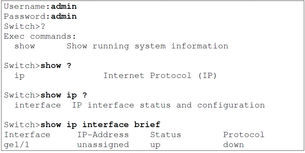
See an example session below, with many lines deleted for clarity.
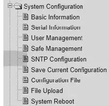
Saving Current Configuration
Configuration changes are not permanent, unless saved. To preserve a configuration change to be used on the next boot-up, save the current configuration using the System Configuration / Save Current Configuration menu option.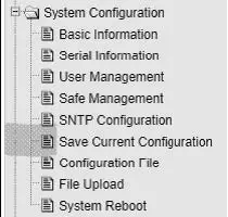
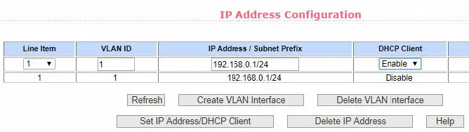
DHCP IP Address
These instructions are to configure the device to obtain its network configuration (IP address, subnet mask, gateway address) from a DHCP server on the same LAN.
After this has been done, consult the DHCP server’s list of leases to learn the IP address of the device.
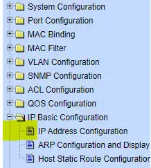
- Select the IP Basic Configuration / IP Address Configuration menu selection.

- Set Line Item to 1 Set DHCP Client to Enable Click Set IP Address/DHCP Client

- The Switch will now query the LAN DHCP server and move to a new IP address. Consult the DHCP server’s list of leases to learn the new IP address of the Switch.
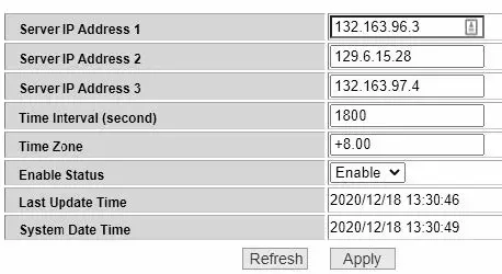
Network Time Client Setup
By default the Simple Network Time Protocol (SNTP) client is disabled. To enable:
- Select the System Configuration / SNMP Configuration menu selection.

- Set Enable Status to Enable,
Set the Time Zone Enter one or more of the Server IP addresses shown below. Click Apply
- Select the System Configuration / Basic Information menu option
You should see the correct time.

If the time is incorrect, that indicates the Switch is unable to connect to the Internet. Start by checking the IP Basic Configuration settings to check the IP address, subnet mask, and default gateway are set correctly. 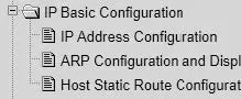
AAA
Authentication, Authorization and Accounting (AAA) features in the switch can be used as follows:
- TACACS+: External authentication for switch management logins.
- 802.1x: External authentication for user network access. 6.5.1. TACACS+
The default behaviour is that switch management interface logins are authenticated against the internal switch database, as configured in System Configuration / User Management.
Alternatively, these logins can be authenticated against an external TACACS+ server.
WARNING:
When you enable & apply TACACS+ authentication, management login to the switch will ONLY use TACACS+. Only save the configuration after confirming you can still login.
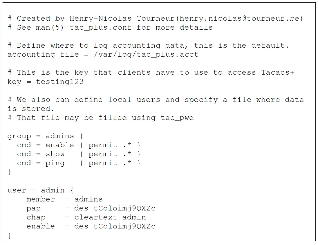
- Setup a TACACS+ server accessible by the switch. Shown below is a simple TACACS+ configuration file that will authenticate switch management logins with Username/Password credentials of admin/admin.

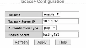
- Select the AAA Configuration / Tacacs+ Configuration menu option and setup similar to as below and click Apply.

- In a new browser window, go to the URL of your switch and confirm you can still login.
If OK: Then select the System Configuration / Save Current Configuration menu option and click Save.
Otherwise: Resolve the TACACS+ problem.
6.5.2. 802.1x (EAP)
The default switch behaviour can be changed such that devices (e.g. PCs) plugged into specified ports have no network connectivity until authorized. 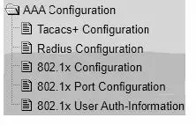
SNMP and MIBs
The Switch supports the Simple Network Management Protocol (SNMP). The Management Information Base (MIB) definition files are available from:
https://ubwh.com.au/documents/WiTek-MIBs.zip
In addition, the Switch can send alerts to a TRAP server.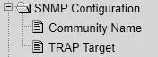
Shown below are some example screen captures from a Windows program called PowerSNMP Free Manager available from
https://www.dart.com/pages/powersnmp-free-manager
Figure 1 – Basic SNMP queries 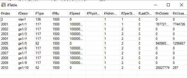
Figure 2 Interface Table Query 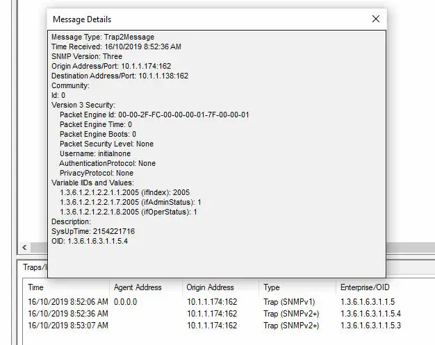
Figure 3 Example Received TRAP messages
Firmware Update
Firmware updates are available from: http://www.wireless-tek.com/Support/download If there is no firmware there for your product, that means there have been no firmware updates.
Update using GUI
- Select the IP Basic Configuration / File Upload menu selection.

- Click Choose file and select the xx.img file downloaded in section 7.
- Click Upload.
- Wait until you see: File uploaded successfully, please reset switch.
- Select the IP Basic Configuration / System Reboot menu selection
- Click Reboot
Update using TFTP
See https://ubwh.com.au/documents/WI-TEK_CLI.pdf


