infineon IR3889 Evaluation Board
Scope and purpose
- The IR3889 is a synchronous buck converter, providing a compact, high-performance and flexible solution in a small 5 mm x 6 mm power QFN package.
- Key features offered by the IR3889 include internal digital soft-start, precision 0.8 V reference voltage, Power Good (PGood), thermal protection, programmable switching frequency, enable input, input Under-Voltage
- Lockout (UVLO) for proper start-up, latched off or unlatched Over-Voltage Protection (OVP), and pre-bias startup.
- The output Over-Current Protection (OCP) function is implemented by sensing the voltage developed across the on-resistance of the synchronous MOSFET for optimum cost and performance and the current limit is thermally compensated.
- This user guide contains the schematic and Bill of Materials (BOM) for the EVAL_3889_1Vout engineering evaluation board. The guide describes operation and use of the evaluation board itself. Detailed application information for IR3889 is available in the IR3889 datasheet.
Intended audience
This document is intended as a guide for design engineers evaluating the performance of IR3889 with the engineering EVAL_3889_1Vout demo board.
Board information
Board features
- Vin = +12 V, Vout = +1 V at 0 to 30 A
- Fs = 800 kHz/1000 kHz
- L= 150 nH (12.4 mm x 8.3 mm x 8 mm, DCR = 0.15 mΩ)
- Cin = 10 x 22 μF (25 V, ceramic 0805) + 1 x 330 μF (25 V, electrolytic, optional)
- Cout = 10 x 22 μF (6.3 V, ceramic 0805) + 4 x 47 μF (6.3 V, ceramic 0805) + 1 x 470 μF (2 V, 6 mΩ, SP-cap)
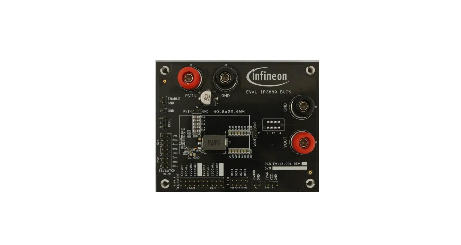
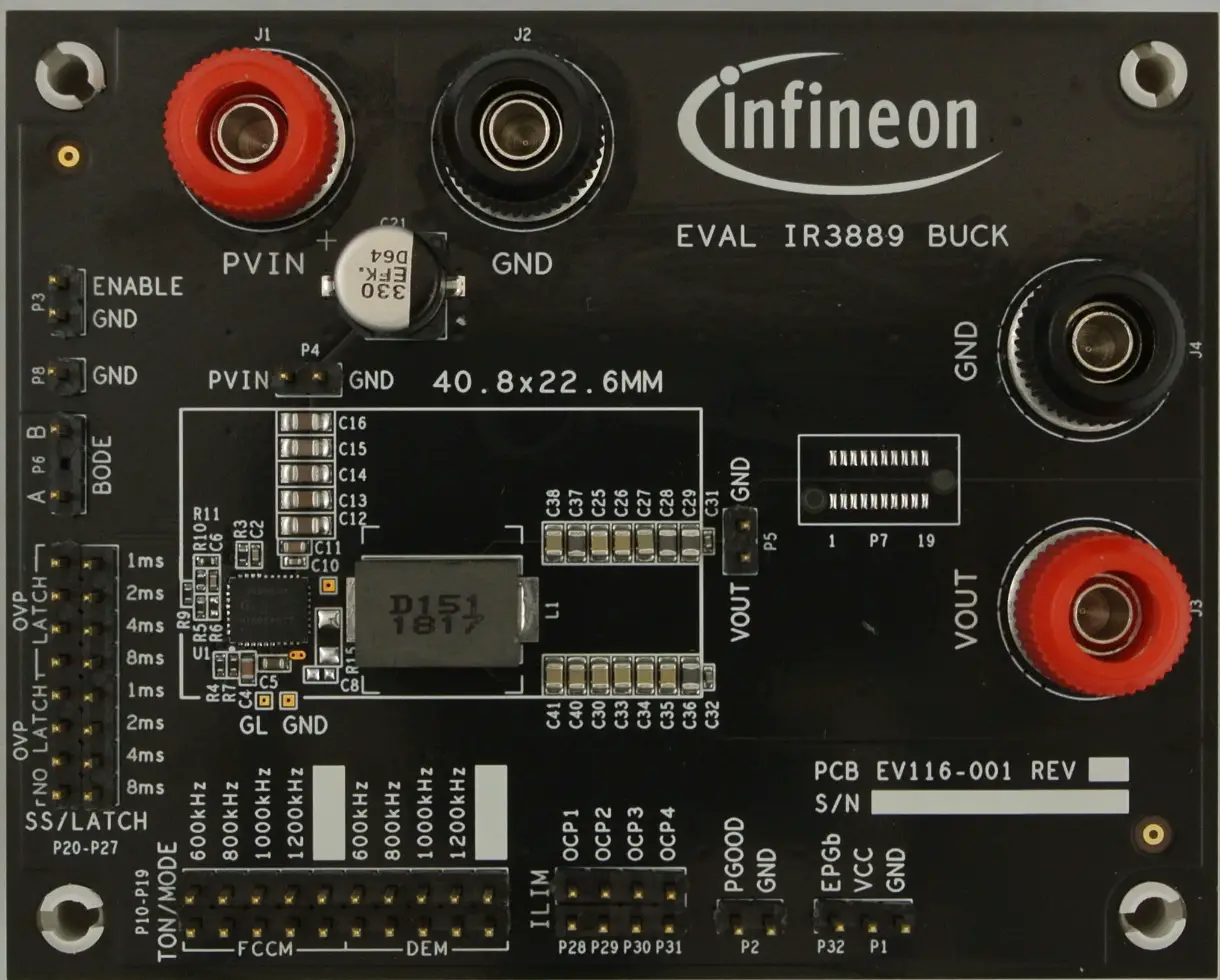
Connections and operating instructions
The IR3889 demo board requires a single +12 V for the input power and can deliver up to 30 A load current. The operation modes and OCP limits can be selected through jumpers.
| Label | Description | |
| Input | PVin | Connect input power (+12 V) to this pin |
| GND | Return of input power | |
| PVin, GND | Sense pins for the input voltage | |
| Output | Vout | Vout (+5 V), connect a load (30 A max.) to this pin |
| GND | Return of Vout | |
| Vout, GND | Sense pins for the output voltage | |
| Enable | Enable | Connect a scope probe to this pin to monitor enable signal Or, an external enable signal can be applied to this pin to over-drive the on- board enable signal |
| GND | ||
| Bode | A | For bode plot measurement |
| B | ||
| SS/Latch | OVP latch | Use a jumper to select one of four soft-start time selections (1 ms, 2 ms, 4 ms and 8 ms), and latched OVP or unlatched OVP |
| OVP no latch | ||
| Ton/Mode | FCCM | Use a jumper to select FCCM or DEM, and switching frequency. The available switching frequencies are 600 kHz, 800 kHz, 1000 kHz and 1200 kHz |
| DEM | ||
| ILIM | Use a jumper to select one of four OCP limits. OCP1 is the lowest OCP limit and OCP4 is the highest OCP limit | |
| PGood | PGOOD | Connect a scope probe to this pin to monitor Power Good signal |
| GND | GND | |
| EPGb | External PGood pull-up bias pin. PGood pin is pulled up to VCC through R4 on the standard demo board. By removing R4 and populating R42 with 49.9 kΩ, an external PGood pull-up bias can be applied to the EPGb pin | |
| VCC | VCC | Standard demo board is configured to use the internal LDO. Connect a scope probe to this pin to monitor the output of the internal LDO |
| GND | ||
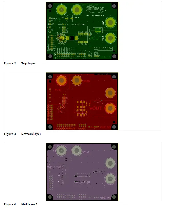
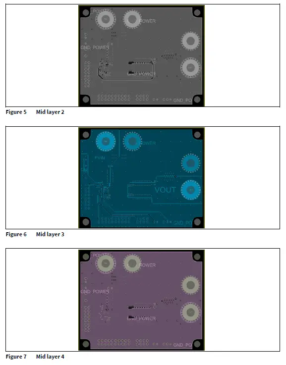
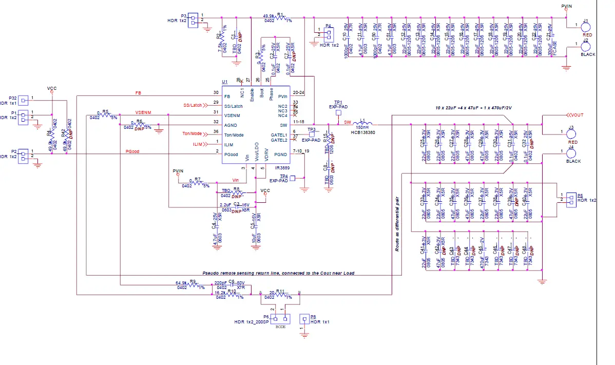
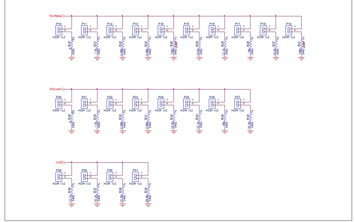
Layout
The PCB is a six-layer board (3.0″ x 3.75″) using FR4 material. Top and bottom layers use 1.5 oz. copper and inner layers use 2 oz. copper. The PCB thickness is 0.062″. The IR3889 and other major power components are mounted on the top side of the board.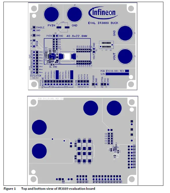
PCB layout

WIRING

Bill of Materials (BOM)
| Item | Qty | Reference | Value | Manufacturer | Part number | Description |
| 1 | 3 | C2, C31, C32 | 0.1 µF | Murata | GRM155R71E104KE14J | Ceramic capacitor 0.1 µF 25 V 10% X7R 0402 |
| 2 | 3 | C4, C11, C51 | 4.7 µF | Murata | GRM188R61E475KE15D | Ceramic capacitor 4.7 µF 25 V 10% X5R 0603 |
| 3 | 1 | C5 | 10 µF | Murata | GRT188R61C106KE13D | Ceramic capacitor 10 µF 16 V ±10% X5R 0603 |
| 4 | 1 | C6 | 220 pF | Murata | GRM155R71H221KA01D | Ceramic capacitor 220 pF 50 V 10% X7R 0402 |
| 5 | 2 | C10, C50 | 1000 pF | Murata | GRM155R61E102KA01D | Ceramic capacitor 1000 pF 25 V 10% X5R 0402 |
| 6 | 10 | C12, C13, C14, C15, C16, C17, | 22 µF | Murata | GRM21BR61E226ME44L | Ceramic capacitor 22 µF 25 V 20% X5R 0805 |
| C18, C19, C20, | ||||||
| C22 | ||||||
| 7 | 1 | C21 | 330 µF | Panasonic | EEV-FK1E331P | Aluminum capacitor 330 µF 20% 25 V SMD |
| 8 | 10 | C25, C26, C27, | 22 µF | TDK | C2012X5R0J226M | Ceramic capacitor 22 µF 6.3 V |
| C30, C33, C34, C35, C38, C40, | X5R 0805 | |||||
| C41 | ||||||
| 9 | 4 | C28, C29, C36, C37 | 47 µF | TDK | C2012X5R0J476M125AC | Ceramic capacitor 47 µF 6.3 V 20% X5R 0805 |
| 10 | 1 | C45 | 470 µF | Panasonic | EEF-SX0D471XE | Aluminum capacitor poly 470 µF 2 V 20% SMD |
| 11 | 1 | L1 | 150 nH | Delta | HCB138380D-151 | Inductor 150 nH, Isat = 80 A 12.4 mm x 8.3 mm x 8 mm DCR = 0.15 mΩ SMD |
| 12 | 2 | R1, R4 | 49.9 k | Panasonic | ERJ-2RKF4992X | RES 49.9 kΩ 1/10 W 1% 0402 SMD |
| 13 | 1 | R2 | 7.5 k | Panasonic | ERJ-2RKF7501X | RES 7.50 kΩ 1/10 W 1% 0402 SMD |
| 14 | 1 | R38 | 21.5 k | Panasonic | ERJ-2RKF2152X | RES 21.5 kΩ 1/10 W 1% 0402 SMD |
| 15 | 5 | R3, R5, R7, R20, R28 | 0 | Panasonic | ERJ-2GE0R00X | RES 0.0 Ω 1/10 W 0402 SMD |
| 16 | 2 | R27, R35 | 16.2 k | Panasonic | ERJ-2RKF1622X | RES 16.2 kΩ 1/10 W 1% 0402 SMD |
| 17 | 1 | R9 | 64.9 k | Panasonic | ERJ-2RKF6492X | RES SMD 64.9 kΩ 1% 1/10 W 0402 |
| 18 | 2 | R10, R37 | 16.2 k | Panasonic | ERJ-2RKF1622X | RES 16.2 kΩ 1/10 W 1% 0402 SMD |
| 19 | 1 | R11 | 20 | Vishay Dale | CRCW040220R0FKED | RES 20.0 Ω 1/16 W 1% 0402 SMD |
| 20 | 2 | R21, R29 | 1.5 k | Panasonic | ERJ-2GEJ152X | RES SMD 1.5 kΩ 5% 1/10 W 0402 |
| 21 | 2 | R22, R30 | 2.49 k | Vishay Dale | CRCW04022K49FKED | RES 2.49 kΩ 1/16 W 1% 0402 SMD |
| 22 | 2 | R23, R31 | 3.48 k | Vishay Dale | CRCW04023K48FKED | RES 3.48 kΩ 1/16 W 1% 0402 SMD |
| 23 | 3 | R24, R32, R36 | 10.5 k | Panasonic | ERJ-2RKF1052X | RES 10.5 kΩ 1/10 W 1% 0402 SMD |
| 24 | 2 | R25, R33 | 12.1 k | Panasonic | ERJ-2RKF1212X | RES 12.1 kΩ 1/10 W 1% 0402 SMD |
| 25 | 2 | R26, R34 | 14 k | Panasonic | ERJ-2RKF1402X | RES 14.0 kΩ 1/10 W 1% 0402 SMD |
| 26 | 1 | R39 | 24.9 k | Panasonic | ERJ-2RKF2492X | RES 24.9 kΩ 1/10 W 1% 0402 SMD |
| 27 | 1 | U1 | IR3889 | Infineon | IR3889 | 30 A single-input voltage, synchronous buck regulator |
Typical operating waveforms


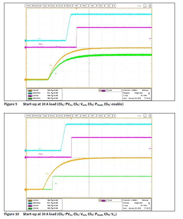
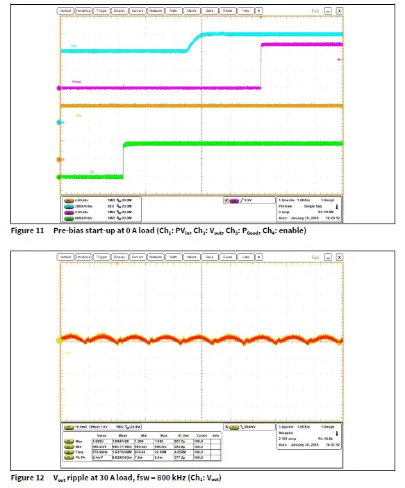
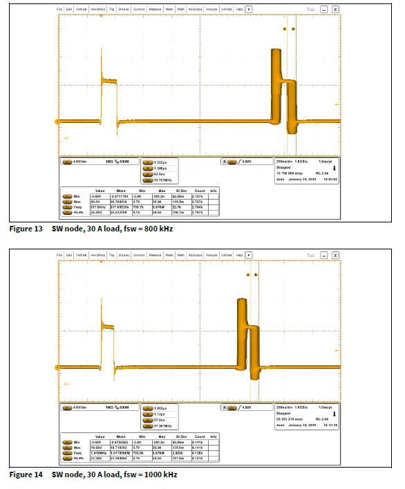
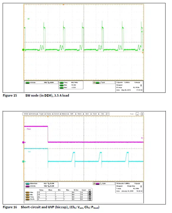
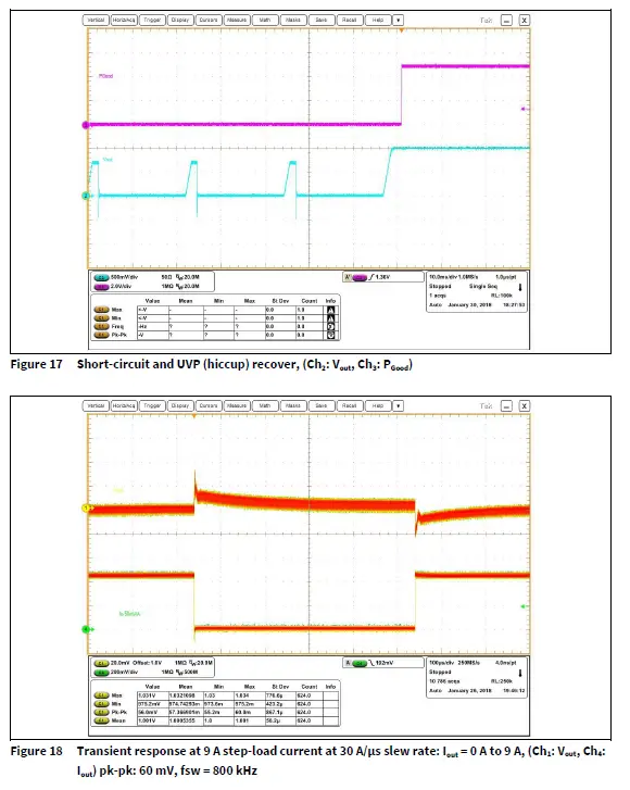
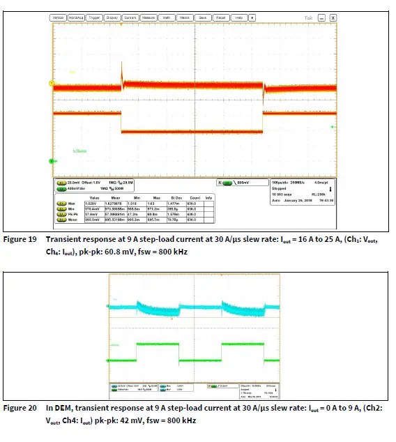
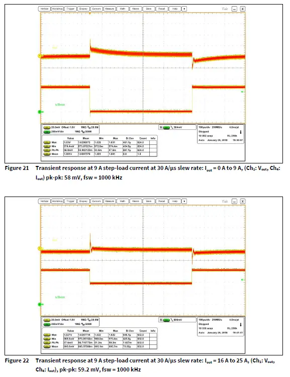
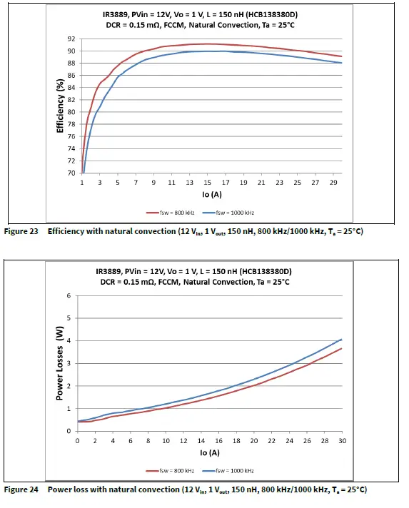
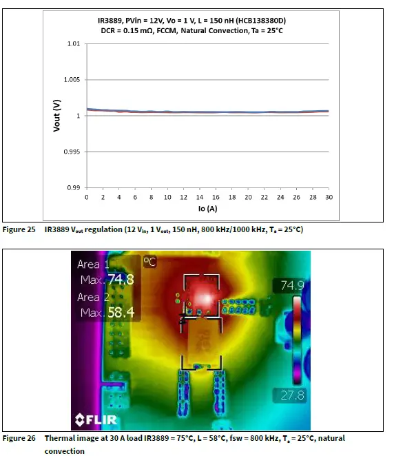
Vin = 12.0 V, Vout = 1V, Iout = 0 to 30 A, room temperature, no air-flow
Revision history
| Document version | Date of release | Description of changes |
| V 1.0 | 2019-06-04 | Initial release |
| V 1.1 | 2022-04-28 |
Edition 2022-04-28 Published by Infineon Technologies AG 81726 Munich, Germany
© 2022 Infineon Technologies AG.
All Rights Reserved.
Do you have a question about this document?
Email: [email protected]
IMPORTANT NOTICE
- The information given in this document shall in no event be regarded as a guarantee of conditions or characteristics (“Beschaffenheitsgarantie”) . With respect to any examples, hints or any typical values stated herein and/or any information regarding the application of the product, Infineon
- Technologies hereby disclaims any and all warranties and liabilities of any kind, including without limitation warranties of non-infringement of intellectual property rights of any third party.
- In addition, any information given in this document is subject to customer’s compliance with its obligations stated in this document and any applicable legal requirements, norms and standards concerning customer’s products and any use of the product of Infineon Technologies in customer’s applications.
- The data contained in this document is exclusively intended for technically trained staff. It is the responsibility of customer’s technical departmentsto evaluate the suitability of the product for the intended application and the completeness of the product information given in this document with respect to such application.
- For further information on the product, technology, delivery terms and conditions and prices please contact your nearest Infineon Technologies office (www.infineon.com).
WARNINGS
Due to technical requirements products may contain dangerous substances. For information on the types in question please contact your nearest Infineon Technologies office.
- Except as otherwise explicitly approved by Infineon
- Technologies in a written document signed by authorized representatives of Infineon
- Technologies, Infineon Technologies’ products may not be used in any applications where a failure of the product or any consequences of the use thereof can reasonably be expected to result in personal injury.
Trademarks
All referenced product or service names and trademarks are the property of their respective owners


