![]() MOD 7-15KTL3-X&MOD 7-11KTL3-X-AU&
MOD 7-15KTL3-X&MOD 7-11KTL3-X-AU&
MOD 7-11 KTL3-X-AU(NDS)&
MOD 12-15KTL3-X(NDS) Quick Guide
1. Overview
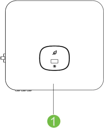
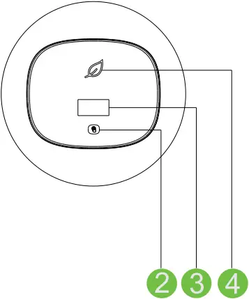
(1) Front panel (2) Touch button (3) LCD screen
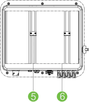
(4) LED indicator (5) Mounting bracket (6) Heat sink
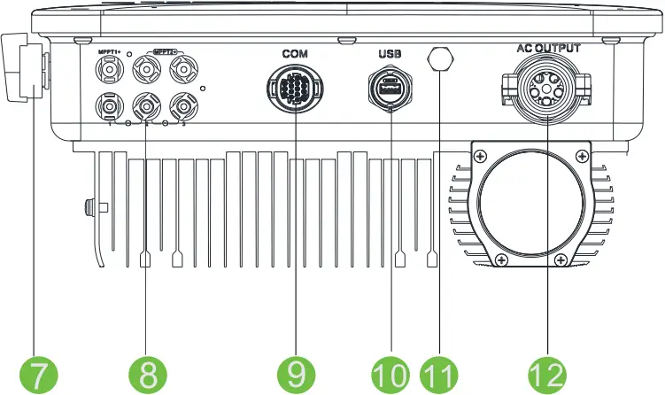
(7) DC switch (8) PV terminal (9) RS485 port
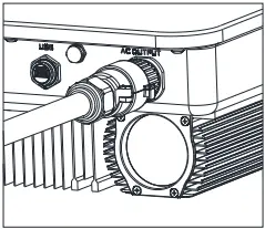
(10) USB port (11) Vent valve (12) AC terminal
![]() Note: Dual MPPTs for MOD 3-11KTL3-X&MOD 3-6KTL3-X(NDS), one string input per MPPT. Dual MPPTs for MOD 7-11KTL3-X-AU& MOD 7-11KTL3-X-AU(NDS)&MOD 12-15KTL3-X &MOD 12-15KTL3-X(NDS), one MPPT has one string, and other one has two strings.
Note: Dual MPPTs for MOD 3-11KTL3-X&MOD 3-6KTL3-X(NDS), one string input per MPPT. Dual MPPTs for MOD 7-11KTL3-X-AU& MOD 7-11KTL3-X-AU(NDS)&MOD 12-15KTL3-X &MOD 12-15KTL3-X(NDS), one MPPT has one string, and other one has two strings.
![]() Note:
Note:
- This document is for quick installation guidance only, please refer to User Manual for more details.
- Growatt shall not be liable for any damage resulting from unproper installation.
2. Installation
System overview
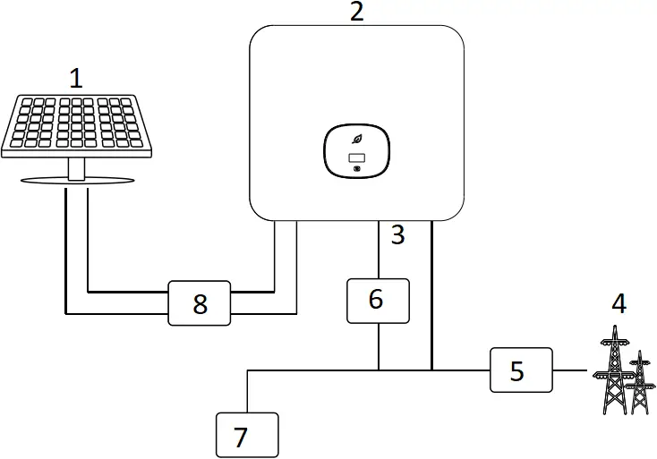
- PV Array
- Inverter
- Grid
- Electrical Grid
- AC Breaker
- Breaker
- Load
- DC Breaker
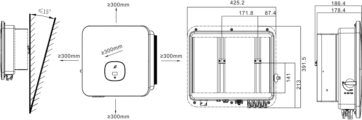
2.1 Installation requirements
2.2 Wall mounting
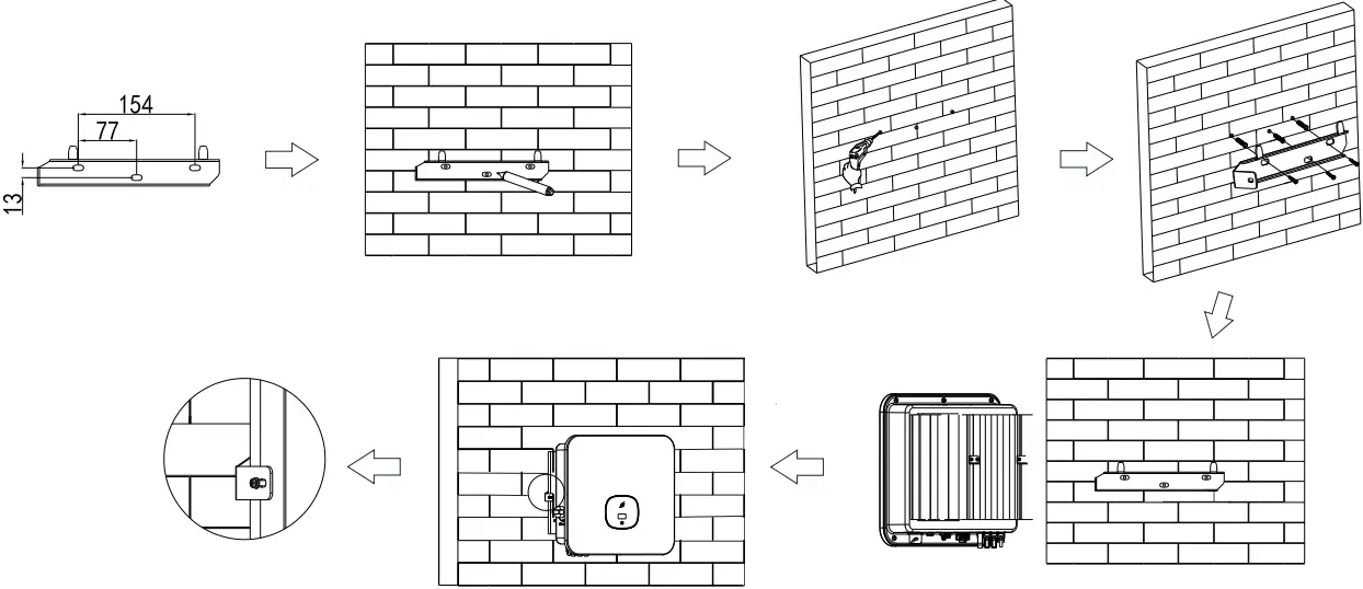
![]() Note:
Note:
- When drilling holes in the wall, avoid water and electricity pipes, otherwise it may cause danger.
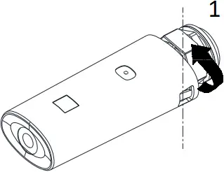
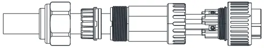
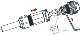
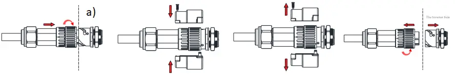
2.3 Communication module installation
Install
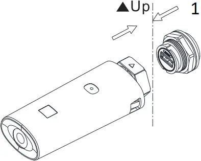
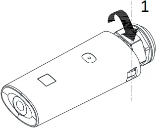
- Inverter side
Uninstall
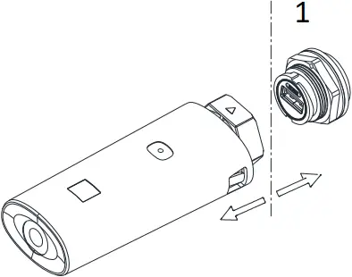
- Inverter side
3. Electrical connection
Please prepare the cable before connecting as follows.
| No. | Cable name | Type | Recommend model |
| 1 | Protective grounding wire | Single multi-core yellow-green wire | 6mm² |
| 2 | AC output wire | Two multi-core or three polychromatic copper wires | 6mm² |
| 3 | PV input wire | PV wire (such as PV1-F) | 4mm² – 6mm² |
| 4 | Communication wire | RS485 | / |
![]() Note:
Note:
- Please make sure all switches are in “OFF” position before wiring. For personal safety, please do not operate with electricity.
- If the diameter of the cable does not match the terminal, or the cable is aluminum wire, please contact our after-sales personnel.
3.1 Grounding
3.2 AC output connection
| 1
| 2
| 3
|
| 4
| 5
| |

3.3 DC connection
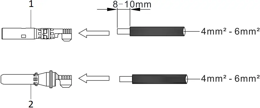
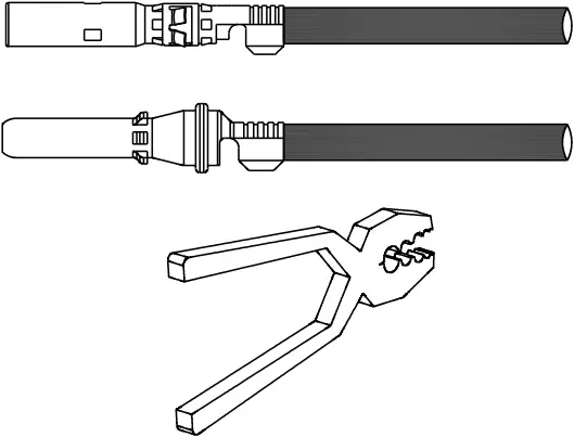
3.3.1 PV input terminal installation
| 1
| 2
Please make sure the cable can not be pulled out after pressing. | 3
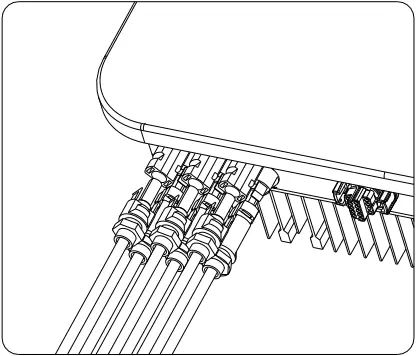
Pull the PV cable make sure there is no loose or shaking. |
| 4
| 5
| |
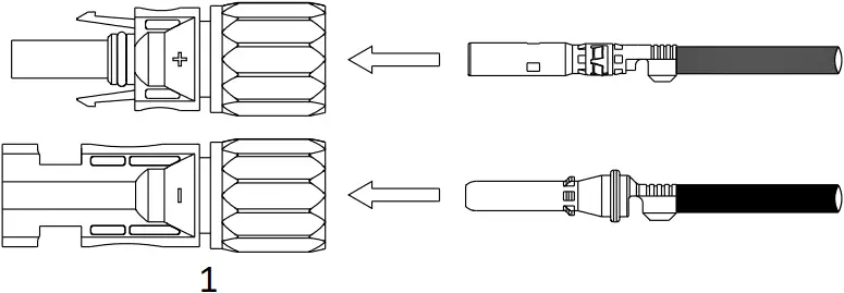
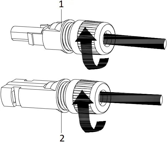
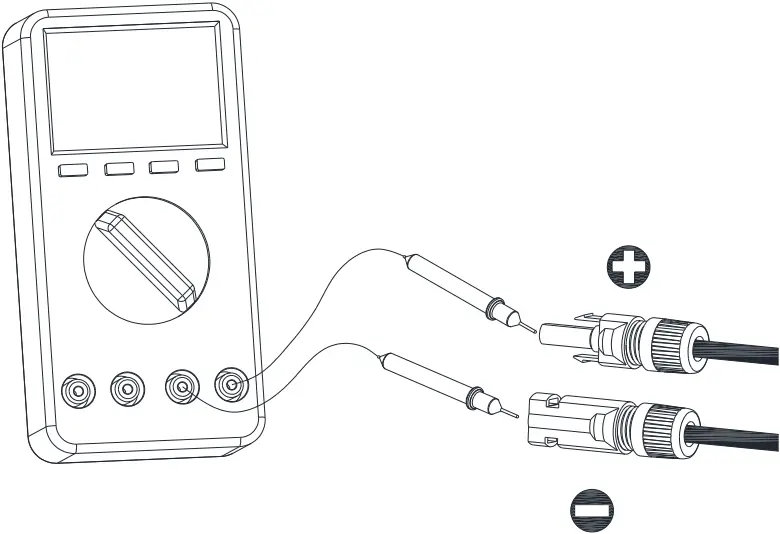 Make sure the cable polarity is correct and voltage is less than 1100V.
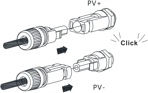
3.3.2 Plug in PV terminal
| 1
| 2
| Note:
|
3.3.3 Communication cable installation
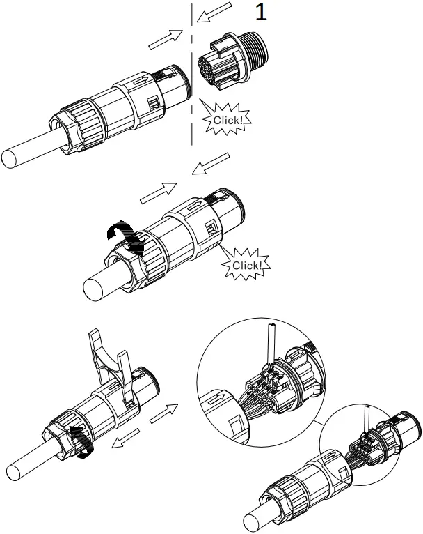
- Inverter side
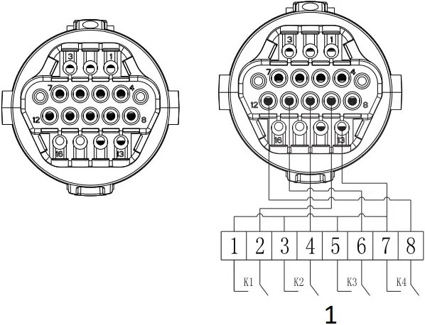
- connect to RRCR
No. | RRCR Description | Active Power |
9 | K1-out | 0% |
10 | K2-out | 30% |
11 | K3-out | 60% |
12 | K4-out | 100% |
13 | Relays common node | / |
14 | / | / |
No. | Description | Remarks |
1 | +12V | Dry junction : external relay coil interface, power is not more than 2W |
2 | COM | |
3 | RS485A1 | RS485 communication port |
4 | RS485B1 | |
5 | RS485A2 | BAT communication port(reserved) |
6 | RS485B2 | |
7 | RS485A3 | Meter communication port |
8 | RS485B3 | |
9 | DRM1/5 | Relay contact 1 input |
10 | DRM2/6 | Relay contact 2 input |
11 | DRM3/7 | Relay contact 3 input |
12 | DRM4/8 | Relay contact 4 input |
13 | REF/GEN | GND |
14 | DRM0/COM | / |
![]() Note:
Note:
When connecting the communication line,port 15 and 16 are not connected, as for the other function,please refer to the above table according to the customer needs.
4. Connecting Meter
The following table describes how we can connect EASTRON meter (TPM-E)to inverter:
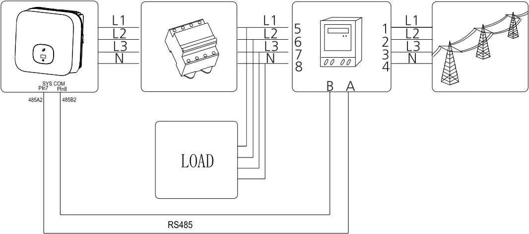
Meter Pin NO. | Description | Meter Connection |
| 1/2/3/4 | L1/L2/L3/N-in | Grid L1/L2/L3/N |
5/6/7/8 | L1/L2/L3/N-out | AC connector & Load L1/L2/L3/N |
| A | RS485A | SYS COM Pin 7 RS485A2 |
B | RS485B | SYS COM Pin 8 RS485B2 |
5. Post-installation check
No. | Acceptance criteria |
1 | The inverter is installed correctly, firmly and reliably. |
2 | The ground wire connected well and the connection is firm and reliable. |
3 | All switches are in the OFF state. |
4 | All wiring is correct and securely connected. |
5 | The requirements, wiring of the cable is reasonable, and there is no meets the phenomenon of broken skin. |
6 | The RS485 communication cable is installed correctly and firmly. |
7 | The cable tie port is trimmed well without leaving sharp corners, meets the requirements of the user. |
8 | All exposed terminals are well protected and there are no vacant ports. |
9 | Pay attention to clean up all construction residues. |
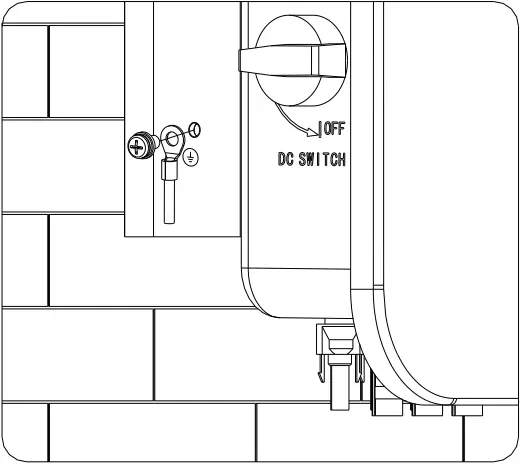
6. Power on and off steps
![]() Note:
Note:
Before turning the inverter on, please make sure the PV input voltage and current are within the MPPT limits.
Follow the steps below to turn the inverter on:
- Switch on the build-in DC isolator at the bottom of the inverter.
- Switch on the PV Array and DC isolator next to your inverter, if you can not find this switch, skip this step.
- Switch on the Solar AC isolator if the inverter is more than 3 meters away from your switchboard.
- Switch on the solar supply main switch in the switch board.
To shut down your system, follow this guide in reverse order.
7. Status of PV grid inverter
Customer can read more information by push button.
Mark | Describe | Explain | |
 | Touch mark | Single touch | Switch the display interface or the current number plus 1 |
| Double touch | Enter the setting state or confirm | ||
Triple touch | Return to the previous display interface | ||
| Long press for 5s | The current data returns to the default value | ||
 | Inverter status indicator | Red | Fault |
| Green | Normal operation | ||
Red light flashing | Warning | ||
| It can display the basic information of inverter through LCD display screen (PV/AC voltage, PV power, AC current, total power, generating capacity, etc.). | |||
8. Export limitation setting
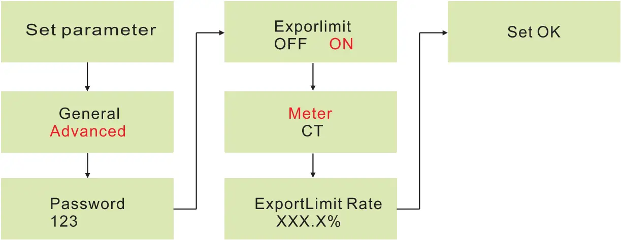
If the local grid company requires to limit the output power from your inverter systems, we introduce the concept of Export Limit Rate. The ratio of your system output power divided by the rated power of the inverter is called Export Limited Rate. For example, if the local grid company only accepts 4kW from your 5kW system, then the Export Limit Rate of 5kW inverter should be 80%.
9. Service and contact
Shenzhen Growatt New Energy Co., Ltd
4-13/F, Building A, Sino-German(Europe) Industrial Park,
Hangcheng Ave, Guxing Community, Xixiang Subdistrict,
Bao’an District, Shenzhen, China
T +86 0755 2747 1942
E [email protected]
W www.ginverter.com


Download Manual ![]()
GR-UM-236-A-02


