![]() SAMRH71-TFBGA-EB User Guide
SAMRH71-TFBGA-EB User Guide
Introduction
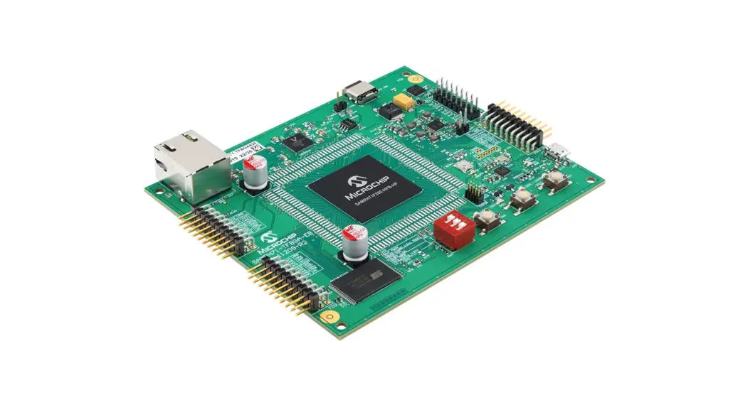
The Microchip SAMRH71-TFBGA-EB evaluation board is a hardware platform to evaluate the SAMRH71 microcontroller in the Hi-Rel plastic package. It supports Microchip’s MPLAB® Harmony integrated development platform, providing easy access to the Radiation-Hardened SAMRH71F20 microcontroller features. The SAMRH71TFBGA-EB is also compliant with extension boards expanding its functionalities.
Features
- SAMRH71F20C-HFB-HP Engineering Sample
- On-board Memory
– SST38VF6401 – 64 MB of PROM – 16 bits wide PROM - On-board Clock Management
– 32.768 kHz Crystal
– 10 MHz Oscillator - Communication Interfaces
– Universal Asynchronous Receiver-Transmitter (UART) through a USB bridge
– Ethernet MAC with External IEEE ® 802.3az 10Base-T/100Base-TX Ethernet RMII PHY (VSC8540 Transceiver)
– CAN (ATA6563 Transceiver)
– External Debug Probe Connector
– PKoB4 Embedded Debugger Accessible through USB - Extension Capability
– 3x Headers Compatible with Xplained Extension Boards
– 4x Connectors with Direct Access to the Processor Pins - On-board End User Interface
– One Mechanical Reset Button
– Three Mechanical User Pushbuttons
– Four User LEDs - 5V Power Supply
– USB-C® Connector
Kit Overview
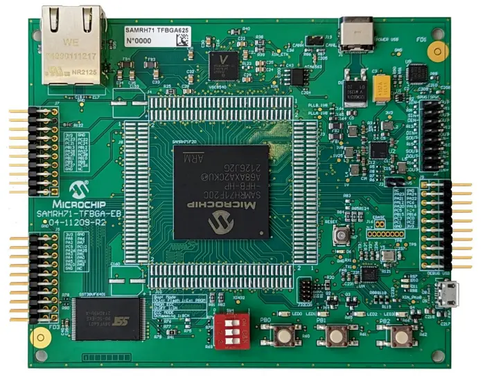
The SAMRH71-TFBGA-EB evaluation board is designed to be more affordable than the SAMRH71F20-EK. It has a compact form factor and embedded debugger, which makes it an ideal board for training or development on the go. It is built around a SAMRH71F20 in TFBGA625 package and provides a reference design for this package. This board is compatible with MPLAB X and the Harmony framework to accelerate your software development. The following figure shows the board layout of SAMRH71-TFBGA-EB.
Figure 1-1. SAMRH71-TFBGA-EB Board Layout
Getting Started
This section provides information about the software tool for the SAMRH71-TFBGA-EB evaluation board.
2.1 Start with MPLAB X IDE
MPLAB X Integrated Development Environment (IDE) is an expandable, highly configurable software program that incorporates powerful tools to help you discover, configure, develop, debug, and qualify embedded designs for most of our microcontrollers and Digital Signal Controllers (DSC). MPLAB X IDE works seamlessly with the MPLAB development ecosystem of software and tools, many of which are completely free.
Hardware User Guide
The following sections provide information about power distribution, SST38VF6401 PROM external memory, connectors, and peripherals.
3.1 Power Distribution
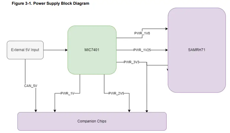
The SAMRH71-TFBGA-EB evaluation board is powered by an external 5V through J1. The board uses a MIC7401 Power Management IC to supply power to the AMRH71 and all the other components on the board:
- 3.3V for SAMRH71 VDDIO and peripherals power supply
- 1.8V for SAMRH71 CORE and PLLs
- 1.25V for SpaceWire reference voltage
- 1V and 2.5V for Ethernet PHY transceiver
- 5V for CAN transceiver
The following figure shows the block diagram of power supply in the SAMRH71-TFBGA-EB evaluation board.
3.2 SST38VF6401 PROM External Memory
The following sections describe SST38VF6401 PROM External Memory.
3.2.1 Memory Overview
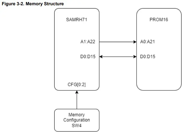
The SAMRH71-TFBGA-EB embeds one SST38VF6401 64M (4M x 16) flash memory (U6). This memory is connected to CS0 and can be selected as boot memory via SW4. The following figure shows memory structure of the SAMRH71-TFBGA-EB kit.
3.2.2 Boot Memory Configuration
SW4 provides the option to select an internal flash or external PROM as the boot memory (onboard SST38VF6401 flash). When you select the external PROM, additional configuration options are available (ECC state and mode).
Note: In version 2.0 of the board, the “ON” and the “OFF” are swapped.
Table 3-1. DIP Switch Configuration
OFF | ON | SAMRH71 Connections | State | Default State | ||
| Pull up on lines | Pull down on lines | 0 | 1 | |||
| Boot Mode | — | — | PF24 | Internal Flash | External PROM | Internal Flash |
| PROM ECC | — | — | PG26 | ECC OFF | ECC ON | ECC OFF |
| ECC Code | — | — | PG27 | Hamming (32, 7) | BCH (32, 12) | Hamming |
3.3 Connectors
The following section describes the SAMRH71-TFBGA-EB connectors and headers pinout.
3.3.1 Extension Headers
The SAMRH71-TFBGA-EB extension headers are compatible with the Microchip Xplained Extension Board format.
The following tables provide the description of the signals that are shared between the headers and on-board features.
Table 3-2. Extension Header 1 (J5)
| EXT1 Pin | SAMRH71 PIN | PIO PeriphA | PIO PeriphB | PIO PeriphC |
| 1 [IDEX] | — | — | — | — |
| 2 [GND] | — | — | — | — |
| 3 [ADC+] | PA9 | FLEXCOM5_IO2 | — | PWMC0_PWMFI1 |
| 4 [ADC-] | PA10 | FLEXCOM5_IO3 | PCK2 | PWMC0_PWMEXTRG0 |
| 5 [GPIO] | PA11 | FLEXCOM5_IO4 | PCK0 | PWMC0_PWMEXTRG1 |
| 6 [GPIO] | PA5 | — | TIOB1 | PWMC0_PWML1 |
| 7 [PWM+] | PA0 | — | TCLK0 | PWMC0_PWMH0 |
| 8 [PWM-] | PA4 | — | TIOA1 | PWMC0_PWML0 |
| 9 [GPIO] | PA1 | — | TIOA0 | PWMC0_PWMH1 |
| 10 [GPIO] | PA3 | FLEXCOM2_IO4 | TCLK1 | PWMC0_PWMH3 |
| 11 [TWI_SDA] | PA25 | FLEXCOM9_IO0 | — | — |
| 12 [TWI_SCL] | PA26 | FLEXCOM9_IO1 | — | — |
| 13 [UART_RX] | PC10 | FLEXCOM5_IO1 | — | — |
| 14 [UART_TX] | PC9 | FLEXCOM5_IO0 | — | — |
| 15 [SPI_SS] | PA7 | FLEXCOM2_IO3 | TIOA2 | PWMC0_PWML3 |
| 16 [SPI_MOSI] | PA2 | FLEXCOM2_IO0 | TIOB0 | PWMC0_PWMH2 |
| 17 [SPI_MISO] | PA6 | FLEXCOM2_IO1 | TCLK2 | PWMC0_PWML2 |
| 18 [SPI_SCK] | PA8 | FLEXCOM2_IO2 | TIOB2 | PWMC0_PWMFI0 |
| 19 [GND] | — | — | — | — |
| 20 [VCC] | — | — | — | — |
Table 3-3. Extension Header 2 (J7)
| EXT2 Pin | SAMRH71 PIN | PIO PeriphA | PIO PeriphB | PIO PeriphC |
| 1 [IDEX] | — | — | — | — |
| 2 [GND] | — | — | — | — |
| 3 [ADC+] | PA23 | FLEXCOM3_IO2 | — | QIO1 |
| 4 [ADC-] | PA24 | FLEXCOM3_IO3 | — | QIO0 |
| 5 [GPIO] | PA21 | FLEXCOM3_IO4 | — | QSCK |
| 6 [GPIO] | PA22 | FLEXCOM3_IO5 | — | QCS |
| 7 [PWM+] | PA12 | FLEXCOM3_IO6 | — | PWMC0_PWMFI2 |
| 8 [PWM-] | PC6 | FLEXCOM4_IO6 | — | — |
| 9 [GPIO] | PA20 | FLEXCOM3_IO0 | PCK0 | QIO2 |
| 10 [GPIO] | PA19 | FLEXCOM3_IO1 | — | QIO3 |
| 11 [TWI_SDA] | PC5 | FLEXCOM4_IO5 | — | — |
| 12 [TWI_SCL] | PC4 | FLEXCOM4_IO4 | — | — |
| 13 [UART_RX] | PB15 | TIOA5 | — | — |
| 14 [UART_TX] | PB16 | TIOB5 | NWDT1 | — |
| 15 [SPI_SS] | PC3 | FLEXCOM4_IO3 | — | — |
| 16 [SPI_MOSI] | PC0 | FLEXCOM4_IO0 | — | — |
| 17 [SPI_MISO] | PC1 | FLEXCOM4_IO1 | — | — |
| 18 [SPI_SCK] | PC2 | FLEXCOM4_IO2 | — | — |
| 19 [GND] | — | — | — | — |
| 20 [VCC] | — | — | — | — |
Table 3-4. Extension Header 3 (J9)
| EXT4 Pin | SAMRH71 PIN | PIO PeriphA | PIO PeriphB | PIO PeriphC |
| 1 [IDEX] | — | — | — | — |
| 2 [GND] | — | — | — | — |
| 3 [ADC+] | PC26 | FLEXCOM0_IO5 | — | TIOA11 |
| 4 [ADC-] | PC27 | FLEXCOM0_IO6 | — | TIOB11 |
| 5 [GPIO] | PB8 | TCLK3 | — | — |
| 6 [GPIO] | PB9 | TIOA3 | — | — |
| 7 [PWM+] | PB10 | TIOB3 | — | — |
| 8 [PWM-] | PB11 | TCLK4 | — | — |
| 9 [GPIO] | PC28 | FLEXCOM0_IO7 | — | TCLK10 |
| 10 [GPIO] | PC25 | FLEXCOM0_IO4 | — | TCLK11 |
| 11 [TWI_SDA] | PA27 | FLEXCOM8_IO0 | — | — |
| 12 [TWI_SCL] | PA28 | FLEXCOM8_IO1 | — | — |
| 13 [UART_RX] | PB12 | TIOA4 | — | — |
| 14 [UART_TX] | PB13 | TIOB4 | — | — |
| 15 [SPI_SS] | PCP | FLEXCOM0_IO3 | — | TIOB9 |
| 16 [SPI_MOSI] | PC21 | FLEXCOM0_IO0 | — | — |
| 17 [SPI_MISO] | PC22 | FLEXCOM0_IO1 | — | — |
| 18 [SPI_SCK] | PC23 | FLEXCOM0_IO2 | — | — |
| 19 [GND] | — | — | — | — |
| 20 [VCC] | — | — | — | — |
3.3.2 Observability Connectors
Four headers (J3, J4, J8, and J10) are located around the SAMRH71 device to provide access to every signal.
3.4 Peripherals
The following sections provide information about the peripherals in the SAMRH71-TFBGA-EB.
3.4.1 Crystals
The SAMRH71-TFBGA-EB has four crystals or oscillators used as clock sources for the board.
- Y1—50 MHz oscillator for the VSC8540 ethernet PHY
- Y2—32.768 kHz crystal for the SAMRH71 slow clock
- Y3—10 MHz oscillator for the SAMRH71 fast clock
- Y4—12 MHz oscillator for the PKoB4 embedded debugger
To test oscillator frequency, all four crystals/oscillators have adjacent test points.
3.4.2 LEDs
PIOs control the four LEDs on the SAMRH71-TFBGA-EB. The following table lists the LED pin connections along with their shared functionality.
Table 3-5. LED Pin Connections
| SAMRH71 PIN | Function | Shared Functionality |
| PB19 | LED0 | PWMC1_PWMH0 |
| PB23 | LED1 | PWMC1_PWML0 |
| PF19 | LED2 | NWR0 |
| PF20 | LED3 | NWR1 |
3.4.3 Mechanical Push Buttons
There are three pushbuttons on the SAMRH71-TFBGA-EB:
- SW5—Reset button
- SW1–SW3—User buttons
When you press a button, it drives the PIO line to GND. The following table lists the mechanical end user push button pin connections.
Table 3-6. Mechanical End User Push Buttons Pin Connections
| SAMRH71 PIN | Function | Shared functionality |
| PC29 | PushButton0 | — |
| PC30 | PushButton1 | — |
| PC31 | PushButton2 | — |
3.4.4 Ethernet
The SAMRH71F20 microcontroller has a built-in 10/100 Mbps ethernet, IEEE 802.3 compatible MAC with RMII, and MII interfaces. The SAMRH71F20-TFBGA-EB features a Microchip VSC8540 RMII physical layer transceiver (PHY) and a compact RJ45 Ethernet connector with built-in magnetics and status LEDs.
Table 3-7. VSC8540 Connections
| SAMRH71 PIN | Function |
| PC11 | RXD1 |
| PC12 | RXD0 |
| PC13 | TXD1 |
| PC14 | TXD0 |
| PC15 | RXER |
| PC16 | CRSDV |
| PC17 | TXEN |
| PC18 | REFCK |
| PC19 | GMDIO |
| PC20 | GMDC |
| PF28 | NRESET |
The VSC8540 default configuration is set via several bootstrap resistors as defined in the following table.
For more information, see the Hardware Mode Strapping in the VSC8540 datasheet.
Table 3-8. VSC8540 Configuration Parameters
Configuration Name | Default Value on SAMRH71 TFBGA Evaluation Board | Default Configuration |
| PHY_ADDRESS | 000 | The default address is 00000 |
| MANAGED_MODE | 1 | The Unmanaged mode is activated |
| CONFIG | 00001 | Delay 0.2 ns 10/100/1000 FDX/HDX, Autoneg ON RMII |
| CLKOUT Enable | 0 | CLKOUT disable |
| CLKOUT Frequency | 01 | CLKOUT Frequency = 50 MHz |
| GMII/MII or RGMII/RMII | 0 | GRMII/RMII enable |
3.4.5 SpaceWire
Both SAMRH71 SpaceWire link 0 and link 1 are grouped on a header (J6). To facilitate loopback test, outputs from one link face inputs from the other (Jumpers are provided in the kit). The following table lists the SpaceWire connections.
Table 3-9. SpaceWire Connections
| SAMRH71 PIN | Function |
| SPWDINP1 and SPWDINN1 | SpaceWire Data Input 1 |
| SPWDOUTP1 and SPWDOUTN1 | SpaceWire Data Output 1 |
| SWPSOUTPP1 1 SWPSOUTPN1 | SpaceWire Strobe Output 1 |
| SPWSINP1 and SPWSINN1 | SpaceWire Strobe Input 1 |
| SPWDINP0 and SPWDINN0 | SpaceWire Data Input 0 |
| SWPDOUTP0 and SWPDOUTN0 | SpaceWire Data Output 0 |
| SWPSOUTPP0 and SOUTHAMPTON | SpaceWire Strobe Output 0 |
| SPWSINP0 and SPWSINN0 | SpaceWire Strobe Input 0 |
3.4.6 CAN
The SAMRH71-TFBGA-EB has one CAN interface connected through an ATA6563 CAN physical transceiver.
The following table lists connections between the SAMRH71 and the ATA6563 transceiver.
Table 3-10. CAN Connections
| SAMRH71 PIN | Function | ATA6563 Function |
| PB6 | CANTX0 | TXD |
| PB7 | CANRX0 | RXD |
| PC7 | GPIO | CAN0 Standby |
3.4.7 UART
The SAMRH71-TFBGA-EB has one UART routed to the DEBUG USB connector (J15). The SAMRH71 UART from FLEXTIME is converted to USB via a CP2103 UART-To-USB converter (U9). For more information, see CP2103 VCP driver. The following table lists the connections between the SAMRH71 and the CP2103 USB to UART bridge.
Table 3-11. UART Connections
| SAMRH71 PIN | Function | CP2103 Function |
| PF29 | FLEXCOM1_IO1 | TXD |
| PF30 | FLECOM1_IO0 | RXD |
3.4.8 Debugger
The following sections describe embedded debugger and external debug probe connector.
3.4.8.1 Embedded Debugger
The SAMRH71-TFBGA-EB features an embedded debugger (PKoB4). The debugger shares the same DEBUG USB port as the virtual COM port mentioned in 3.4.7. UART. When not programming, the PKoB4 keeps its I/Os in high impedance to not interfere with an external debugger if such device is needed.
Table 3-12. PKoB4 Connection
| SAMRH71 PIN | Utility |
| PA16 | PKoB4 SWCLK |
| PA17 | PKoB4 SWDIO |
3.4.8.2 External Debug Probe Connector
The SAMRH71-TFGBA-EB has a 2 x 5-pin Debug Probe Connector (J32CON) supporting the SWD protocol. These pins are shared with the on-board debugger (PKoB4) and use if you prefer an external debugger (J32, ICD4, PicKit4 and so on).
Table 3-13. J32CON Header
| Header Pin | SAMRH71 PIN | Utility |
| 1 | — | Power 3V3 |
| 7 | — | NC |
| 3-5-9 | — | Ground |
| 8 | PB1 | TDI |
| 2 | PA17 | TMS/SWDIO |
| 4 | PA16 | TCK/SWCLK |
| 6 | PB3 | TDO |
| 10 | — | NRESET |
Revision History
| Revision | Date | Description |
| A | Nov-22 | Initial Revision |
Microchip Information
The Microchip Website
Microchip provides online support via our website at www.microchip.com/. This website is used to make files and information easily available to customers. Some of the content available includes:
- Product Support – Data sheets and errata, application notes and sample programs, design resources, user’s guides and hardware support documents, latest software releases and archived software
- General Technical Support – Frequently Asked Questions (FAQs), technical support requests, online discussion groups, Microchip design partner program member listing
- Business of Microchip – Product selector and ordering guides, latest Microchip press releases, listing of seminars and events, listings of Microchip sales offices, distributors and factory representatives
Product Change Notification Service
Microchip’s product change notification service helps keep customers current on Microchip products. Subscribers will receive email notification whenever there are changes, updates, revisions or errata related to a specified product family or development tool of interest.
To register, go to www.microchip.com/pcn and follow the registration instructions.
Customer Support
Users of Microchip products can receive assistance through several channels:
- Distributor or Representative
- Local Sales Office
- Embedded Solutions Engineer (ESE)
- Technical Support
Customers should contact their distributor, representative or ESE for support. Local sales offices are also available to help customers. A listing of sales offices and locations is included in this document.
Technical support is available through the website at: www.microchip.com/support
Microchip Devices Code Protection Feature
Note the following details of the code protection feature on Microchip products:
- Microchip products meet the specifications contained in their particular Microchip Data Sheet.
- Microchip believes that its family of products is secure when used in the intended manner, within operating specifications, and under normal conditions.
- Microchip values and aggressively protects its intellectual property rights. Attempts to breach the code protection features of Microchip product is strictly prohibited and may violate the Digital Millennium Copyright Act.
- Neither Microchip nor any other semiconductor manufacturer can guarantee the security of its code. Code protection does not mean that we are guaranteeing the product is “unbreakable”. Code protection is constantly evolving. Microchip is committed to continuously improving the code protection features of our products.
Legal Notice
This publication and the information herein may be used only with Microchip products, including to design, test, and integrate Microchip products with your application. Use of this information in any other manner violates these terms. Information regarding device applications is provided only for your convenience and may be superseded by updates. It is your responsibility to ensure that your application meets with your specifications. Contact your local Microchip sales office for additional support or, obtain additional support at www.microchip.com/en-us/support/design-help/client-support-services.
THIS INFORMATION IS PROVIDED BY MICROCHIP “AS IS”. MICROCHIP MAKES NO REPRESENTATIONS OR WARRANTIES OF ANY KIND WHETHER EXPRESS OR IMPLIED, WRITTEN OR ORAL, STATUTORY OR OTHERWISE, RELATED TO THE INFORMATION INCLUDING BUT NOT LIMITED TO ANY IMPLIED WARRANTIES OF NON-INFRINGEMENT, MERCHANTABILITY, AND FITNESS FOR A PARTICULAR PURPOSE, OR WARRANTIES RELATED TO ITS CONDITION, QUALITY, OR PERFORMANCE. IN NO EVENT WILL MICROCHIP BE LIABLE FOR ANY INDIRECT, SPECIAL, PUNITIVE, INCIDENTAL, OR CONSEQUENTIAL LOSS, DAMAGE, COST, OR EXPENSE OF ANY KIND WHATSOEVER RELATED TO THE INFORMATION OR ITS USE, HOWEVER CAUSED, EVEN IF MICROCHIP HAS BEEN ADVISED OF THE POSSIBILITY OR THE DAMAGES ARE FORESEEABLE. TO THE FULLEST EXTENT ALLOWED BY LAW, MICROCHIP’S TOTAL LIABILITY ON ALL CLAIMS IN ANY WAY RELATED TO THE INFORMATION OR ITS USE WILL NOT EXCEED THE AMOUNT OF FEES, IF ANY, THAT YOU HAVE PAID DIRECTLY TO MICROCHIP FOR THE INFORMATION.
Use of Microchip devices in life support and/or safety applications is entirely at the buyer’s risk, and the buyer agrees to defend, indemnify and hold harmless Microchip from any and all damages, claims, suits, or expenses resulting from such use. No licenses are conveyed, implicitly or otherwise, under any Microchip intellectual property rights unless otherwise stated.
Trademarks
The Microchip name and logo, the Microchip logo, Adaptec, AVR, AVR logo, AVR Freaks, BesTime, BitCloud, CryptoMemory, CryptoRF, dsPIC, flexPWR, HELDO, IGLOO, JukeBlox, KeeLoq, Kleer, LANCheck, LinkMD, maXStylus, maXTouch, MediaLB, megaAVR, Microsemi, Microsemi logo, MOST, MOST logo, MPLAB, OptoLyzer, PIC, picoPower, PICSTART, PIC32 logo, PolarFire, Prochip Designer, QTouch, SAM-BA, SenGenuity, SpyNIC, SST, SST Logo, SuperFlash, Symmetricom, SyncServer, Tachyon, TimeSource, tinyAVR, UNI/O, Vectron, and XMEGA are registered trademarks of Microchip Technology Incorporated in the U.S.A. and other countries. AgileSwitch, APT, ClockWorks, The Embedded Control Solutions Company, EtherSynch, Flashtec, Hyper Speed Control, HyperLight Load, Libero, motorBench, mTouch, Powermite 3, Precision Edge, ProASIC, ProASIC Plus, ProASIC Plus logo, Quiet- Wire, SmartFusion, SyncWorld, Temux, TimeCesium, TimeHub, TimePictra, TimeProvider, TrueTime, and ZL are registered trademarks of Microchip Technology Incorporated in the U.S.A.
Adjacent Key Suppression, AKS, Analog-for-the-Digital Age, Any Capacitor, AnyIn, AnyOut, Augmented Switching, BlueSky, BodyCom, Clockstudio, CodeGuard, CryptoAuthentication, CryptoAutomotive, CryptoCompanion, CryptoController, dsPICDEM, dsPICDEM.net, Dynamic Average Matching, DAM, ECAN, Espresso T1S, EtherGREEN, GridTime, IdealBridge, In-Circuit Serial Programming, ICSP, INICnet, Intelligent Paralleling, IntelliMOS, Inter-Chip Connectivity, JitterBlocker, Knob-on-Display, KoD, maxCrypto, maxView, memBrain, Mindi, MiWi, MPASM, MPF, MPLAB Certified logo, MPLIB, MPLINK, MultiTRAK, NetDetach, Omniscient Code Generation, PICDEM, PICDEM.net, PICkit, PICtail, PowerSmart, PureSilicon, QMatrix, REAL ICE, Ripple Blocker, RTAX, RTG4, SAMICE, Serial Quad I/O, simpleMAP, SimpliPHY, SmartBuffer, SmartHLS, SMART-I.S., storClad, SQI, SuperSwitcher, SuperSwitcher II, Switchtec, SynchroPHY, Total Endurance, Trusted Time, TSHARC, USBCheck, VariSense, VectorBlox, VeriPHY, ViewSpan, WiperLock, XpressConnect, and ZENA are trademarks of Microchip Technology Incorporated in the U.S.A. and other countries. SQTP is a service mark of Microchip Technology Incorporated in the U.S.A.
The Adaptec logo, Frequency on Demand, Silicon Storage Technology, and Symmcom are registered trademarks of Microchip Technology Inc. in other countries.
GestIC is a registered trademark of Microchip Technology Germany II GmbH & Co. KG, a subsidiary of Microchip Technology Inc., in other countries.
All other trademarks mentioned herein are property of their respective companies.
© 2022, Microchip Technology Incorporated and its subsidiaries. All Rights Reserved.
ISBN: 978-1-6683-1548-4
Quality Management System
For information regarding Microchip’s Quality Management Systems, please visit www.microchip.com/quality.
Worldwide Sales and Service
| AMERICAS | ASIA/PACIFIC | ASIA/PACIFIC | EUROPE |
| Corporate Office 2355 West Chandler Blvd. Chandler, AZ 85224-6199 Tel: 480-792-7200 Fax: 480-792-7277 Technical Support: www.microchip.com/support Web Address: www.microchip.com Atlanta Duluth, GA Tel: 678-957-9614 Fax: 678-957-1455 Austin, TX Tel: 512-257-3370 Boston Westborough, MA Tel: 774-760-0087 Fax: 774-760-0088 Chicago Itasca, IL Tel: 630-285-0071 Fax: 630-285-0075 Dallas Addison, TX Tel: 972-818-7423 Fax: 972-818-2924 Detroit Novi, MI Tel: 248-848-4000 Houston, TX Tel: 281-894-5983 Indianapolis Noblesville, IN Tel: 317-773-8323 Fax: 317-773-5453 Tel: 317-536-2380 Los Angeles Mission Viejo, CA Tel: 949-462-9523 Fax: 949-462-9608 Tel: 951-273-7800 Raleigh, NC Tel: 919-844-7510 New York, NY Tel: 631-435-6000 San Jose, CA Tel: 408-735-9110 Tel: 408-436-4270 Canada – Toronto Tel: 905-695-1980 Fax: 905-695-2078 | Australia – Sydney Tel: 61-2-9868-6733 China – Beijing Tel: 86-10-8569-7000 China – Chengdu Tel: 86-28-8665-5511 China – Chongqing Tel: 86-23-8980-9588 China – Dongguan Tel: 86-769-8702-9880 China – Guangzhou Tel: 86-20-8755-8029 China – Hangzhou Tel: 86-571-8792-8115 China – Hong Kong SAR Tel: 852-2943-5100 China – Nanjing Tel: 86-25-8473-2460 China – Qingdao Tel: 86-532-8502-7355 China – Shanghai Tel: 86-21-3326-8000 China – Shenyang Tel: 86-24-2334-2829 China – Shenzhen Tel: 86-755-8864-2200 China – Suzhou Tel: 86-186-6233-1526 China – Wuhan Tel: 86-27-5980-5300 China – Xian Tel: 86-29-8833-7252 China – Xiamen Tel: 86-592-2388138 China – Zhuhai Tel: 86-756-3210040 | India – Bangalore Tel: 91-80-3090-4444 India – New Delhi Tel: 91-11-4160-8631 India – Pune Tel: 91-20-4121-0141 Japan – Osaka Tel: 81-6-6152-7160 Japan – Tokyo Tel: 81-3-6880- 3770 Korea – Daegu Tel: 82-53-744-4301 Korea – Seoul Tel: 82-2-554-7200 Malaysia – Kuala Lumpur Tel: 60-3-7651-7906 Malaysia – Penang Tel: 60-4-227-8870 Philippines – Manila Tel: 63-2-634-9065 Singapore Tel: 65-6334-8870 Taiwan – Hsin Chu Tel: 886-3-577-8366 Taiwan – Kaohsiung Tel: 886-7-213-7830 Taiwan – Taipei Tel: 886-2-2508-8600 Thailand – Bangkok Tel: 66-2-694-1351 Vietnam – Ho Chi Minh Tel: 84-28-5448-2100 | Austria – Wels Tel: 43-7242-2244-39 Fax: 43-7242-2244-393 Denmark – Copenhagen Tel: 45-4485-5910 Fax: 45-4485-2829 Finland – Espoo Tel: 358-9-4520-820 France – Paris Tel: 33-1-69-53-63-20 Fax: 33-1-69-30-90-79 Germany – Garching Tel: 49-8931-9700 Germany – Haan Tel: 49-2129-3766400 Germany – Heilbronn Tel: 49-7131-72400 Germany – Karlsruhe Tel: 49-721-625370 Germany – Munich Tel: 49-89-627-144-0 Fax: 49-89-627-144-44 Germany – Rosenheim Tel: 49-8031-354-560 Israel – Ra’anana Tel: 972-9-744-7705 Italy – Milan Tel: 39-0331-742611 Fax: 39-0331-466781 Italy – Padova Tel: 39-049-7625286 Netherlands – Drunen Tel: 31-416-690399 Fax: 31-416-690340 Norway – Trondheim Tel: 47-72884388 Poland – Warsaw Tel: 48-22-3325737 Romania – Bucharest Tel: 40-21-407-87-50 Spain – Madrid Tel: 34-91-708-08-90 Fax: 34-91-708-08-91 Sweden – Gothenberg Tel: 46-31-704-60-40 Sweden – Stockholm Tel: 46-8-5090-4654 UK – Wokingham Tel: 44-118-921-5800 Fax: 44-118-921-5820 |
![]() © 2022 Microchip Technology Inc. and its subsidiaries
© 2022 Microchip Technology Inc. and its subsidiaries
DS50003449A-page 17
References
 青娱乐极品盛宴_午夜羞羞影院男女爽爽爽_白丝小舞被啪到娇喘不停_狠狠综合久久久综合网大蛇
 Empowering Innovation | Microchip Technology
-
Empowering Innovation | Microchip Technology
-
Support | Microchip Technology
-
Product Change Notification | Microchip Technology
-
Quality | Microchip Technology
-
Microchip Lightning Support
-
Empowering Innovation | Microchip Technology
-
Empowering Innovation | Microchip Technology
-
microchip.com/en-us/product/VSC8540
-
Client Support Services | Microchip Technology
-
Product Change Notification | Microchip Technology
-
Quality | Microchip Technology
-
Microchip Lightning Support
-
CP210x USB to UART Bridge VCP Drivers - Silicon Labs


