infobit 409R iWall 4K UHD 4×9 Video Wall Controller  Overview
 Overview
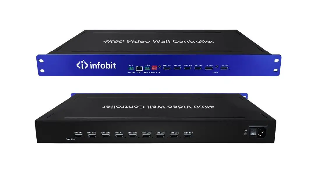
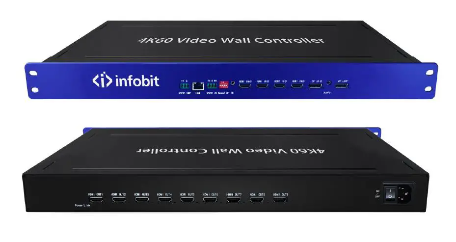
The iWall 409R is a 4K Ultra HD video wall controller designed by INFOBIT AV. Supports 4x HDMI inputs (1x 4K@60Hz, 3x 4K@30Hz), 1x DP input (4K@60Hz), 9x HDMI outputs
(1080p@60Hz), and 1x DP loop out.
A single device, 5 inputs and 9 outputs (compatible with 1 in 9 out), can be combined in any number of video wall layout modes of landscape or portrait installation, and large-scale video wall can be connected by cascading more 409R.
It supports 4 source windows on the whole wall in multiple displaying modes: single image, PIP (Picture in Picture), POP (Picture on Picture), PYP ( Picture by Picture: Up-Down or Left-Right side by side) or Quad-view.
It supports maximum input 3840×2160@60Hz and backwards compatible and maximum output 1920×1080@60Hz.
The source can be rotated 90°(only in single picture mode), and the upper image rotated 180°(only under picture by picture side by side by up-down mode).
- No stretching, deformation, or compression.
- Supports matrix model (single display mode 1×1).
- Support IR remote control and serial RS232 control.
- Fan-less design: Low power consumption fan-less design.
- Inputs can be PC, media player, blue ray, game console and other devices.
- Using 40nm high-end programmable FPGA chip, pure hardware real-time processing architecture without delay. Without Window blue screen, virus risks, OS vulnerability, and breakdown. Lower requirements of IT technology background, save your training cost.
Application
It is mainly used in industrial applications such as ultra-high-definition video surveillance, large-scale video walls, advertising, exhibitions, conference, and digital signage.
Specifications
| Product name | iWall 409R |
| Input Max. pixel FPS | 600MHz |
| DisplayPort input | 1x Display port 1.2 (3840×2160@60Hz) |
| HDMI inputs | 3x HDMI 1.4 (3840×2160@30H)- HDMI IN 1-3 1x HDMI 2.0 (3840×2160@60H)- HDMI IN 4 |
| Output Max. Pixel FPS | 165MHz |
| HDMI outputs | 9x HDMI 1.3 (1920*1080@60Hz) |
| Loop-out | 1x Display port 1.2 (3840×2160@60Hz) |
| Audio output | 1x 3.5mm |
| Control | Remote control, RS232 |
| Factory default resolution | HDMI:3840*2160@30Hz DP:3840*2160@60Hz |
| Support custom resolution | Yes |
| Operating temperature | 0℃-50℃ |
| Power consumption | 12W |
| Power supply | 12V@2A AC-DC |
| Net Weight | 840g |
| Size | 270*122.5*20mm WDH |
| Package list | One DP Cable One 12V@2A AC-DC One remote control |
| Warranty | 3 years |
Operation instructions
Product panel description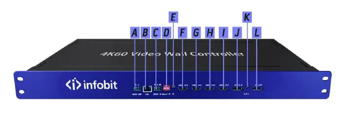
A: RS232 loop out, used to loop out the RS232 commands to the next cascaded device.
B:TCP/IP control
C:RS232 control
D:DIP switch (Board ID): indicates the ID of the current device in cascading mode. For detailed settings, see below DIP list.
E:IR control
F, G, H and I: HDMI inputs 1-4, of which I (#4) port supports 4K60, F/G/H port (#1-3) supports 4K30. With LED indicators showing input status.
J: 1 DP input interface, maximum 4K60Hz.
K: Audio output
L: DP Loop-out for cascading
(In single picture mode, the loop-out follows the selection of the input source channel. In other modes, only the DP input source can be loop-out). 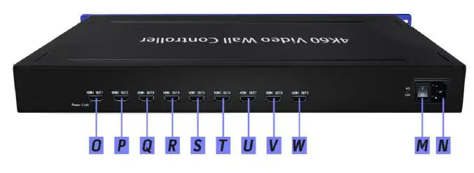
O, P, Q, R, S, T, U, V,W: HDMI outputs 1-9
M: Switch ON/OFF
N: Power supply.
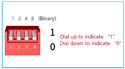
List 1: DIP switch (When cascading, it indicates the current device ID, set in binary.)
| Device # | ID | Device # | ID |
| Device 1 | 1000 | Device 9 | 1001 |
| Device 2 | 0100 | Device 10 | 0101 |
| Device 3 | 1100 | Device 11 | 1101 |
| Device 4 | 0010 | Device 12 | 0011 |
| Device 5 | 1010 | Device 13 | 1011 |
| Device 6 | 0110 | Device 14 | 0111 |
| Device 7 | 1110 | Device 15 | 1111 |
| Device 8 | 0001 |
Remote control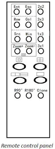
| Buttons | Features |
| Ent | Confirm key |
| Esc | Escape key |
| Row | Set layouts mode: row (range: 1-16) |
| Col | Set layouts mode: column (range: 1-16) |
| Src | Source:Enter the number of the source, 1 for HDMI #1, 2 for HDMI #2, 3 for HDMI #3, 4 for HDMI #4, 5 for DP IN #5. |
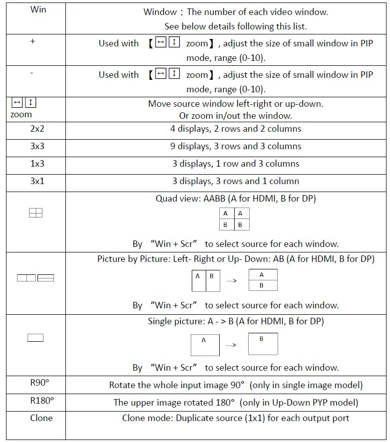
Note 1:
[win] key meaning: image window, the number of each screen (window) on the whole video wall, the corresponding position is as follows.
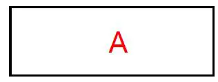
Single screen mode: there is only one image, and the value is fixed as No. A, as shown below.
Picture in Picture mode: The value of the large picture is No. A, and the value of the small picture is No. B, as shown in the following figure. 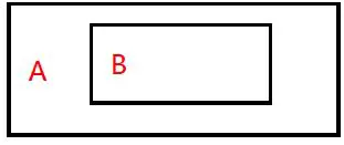 Picture by Picture (Left right mode): The left screen value is No. A, and the right screen value is No. B, as shown below.
 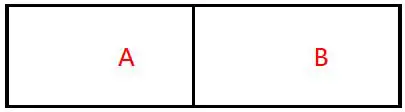 Picture by Picture (Up down mode): The upper screen value is No. A, and the lower screen value is No. B, as shown below.
 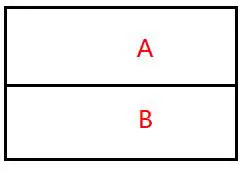 Quad view mode:The value of the upper left screen is No. A, the value of the bottom left screen is No. B, the value of the upper right screen is No. C, and the value of the bottom right screen is No. D, as shown in the following figure.
Remote control operation instructions
The adjustment of the following two groups of parameters needs to press the [Ent] confirmation key to take effect, and the [Esc] key to cancel.
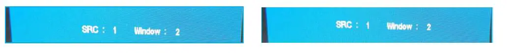
[ROW, COL] is a group to adjust the output layouts mode. You can confirm the value by viewing the OSD display information in the top left corner of the whole wall.
For example: If you need to adjust to 2×3 (two rows and three columns) video wall, you need to set [row] to 2, and [COL] to 3. Press [Ent] to confirm.

[Src, Win] is a group. The purpose is to arbitrarily specify the input source channel for each image window. You can confirm the value by viewing the OSD display information in the top left corner of the whole video wall.
For example: Currently, it is in [ ![]() ] PIP mode, HDMI #1 is displayed in the larger window and HDMI #2 is displayed in the smaller window by default. If you need to adjust the large window to show HDMI #2 and the small window to show HDMI #1. Then you need to set
] PIP mode, HDMI #1 is displayed in the larger window and HDMI #2 is displayed in the smaller window by default. If you need to adjust the large window to show HDMI #2 and the small window to show HDMI #1. Then you need to set
[Win] to “1”(window No. 1 means larger window), [Src] is “2” (2 means HDMI#2
input),After pressing the [Ent] to confirm the selection. Do the same operation for the
smaller window.
![]() are one group, used to adjust position and size of the smaller image window when under Picture in Picture mode.
are one group, used to adjust position and size of the smaller image window when under Picture in Picture mode.
- Press Zoom at the first time, press + – buttons to adjust the position ( + to move to right, – to move to left)
- Press at the second time, press + – buttons to adjust the position ( + to move down, – to move up)
- Press at the third time, press + – buttons to adjust the size ( + to zoom out, – to zoom in)

RS232 control
- Baud Rate: 9600
- Data bit: 8 bits
- Stop bit: 1 bit, no parity
| Function | Byte 1 cmd_head | Byte 2 cmd_type | Byte 3 cmd_data1 | Byte 4 cmd_data2 | Byte 5 Check_sum |
| Video wall mode | 0x66 | 0x01 | Row | Col | byte 1 + byte 2 |
| + byte 3 + byte 4 | |||||
| Rotate 90 ° | 0x66 | 0x02 | Rotate9 0 | 0x00 | byte 1 + byte 2 + byte 3 + byte 4 |
| Rotate 180 ° | 0x66 | 0x03 | Rotate1 80 | 0x00 | byte 1 + byte 2 + byte 3 + byte 4 |
| Multi pictures mode | 0x66 | 0x04 | Mode | 0x00 | byte 1 + byte 2 + byte 3 + byte 4 |
| Multi pictures window specify input source | 0x66 | 0x05 | Window Sel | Source Channel | byte 1 + byte 2 + byte 3 + byte 4 |
| PIP Small window position | 0x66 | 0x06 | Position | 0x00 | byte 1 + byte 2 + byte 3 + byte 4 |
| PIP Small window size | 0x66 | 0x07 | Size | 0x00 | byte 1 + byte 2 + byte 3 + byte 4 |
Description:
- [Row]: Video Wall mode: Row
- [Col]: Video Wall mode: Column
- [Rotate90]: Rotate 90°:
- 0: rotate
- 1: do not rotate (only supported in single-screen mode)
- [Rotate180]: Rotate 180°:
- 0: rotate,
- 1: not rotate (only supported in stitching mode behavior 2)
- [Mode]: Multi-picture mode:
- 0: single screen
- 1: left-right PYP
- 2: four pictures quad-view
- 3: PIP double screen
- 4: up-down PYP
- [WindowSel]: Window selection, the value depends on the setting of multi-screen mode:
- [Mode]=0, WindowSel=0 (current screen)
- [Mode]=1, WindowSel=0 (left picture), WindowSel=1 (right picture)
- [Mode]=2, WindowSel=0 (upper left screen), WindowSel=1 (lower left screen) WindowSel=2 (upper right screen), WindowSel=3 (lower right screen)
- [Mode]=3, WindowSel=0 (large picture), WindowSel=1 (small picture)
- [Mode]=4, WindowSel=0 (upper screen), WindowSel=1 (lower screen)
- [SourceChannel]: Input source channel selection: 0 is HDM I, 1 is HDMI 2, 2 is HDMI 3, 3 is HDMI 4, 4 is DP 5.
- [Position]: Choose the position of the small window in the picture-in-picture mode: 0: center, 1: upper left corner, 2: upper right corner, 3: bottom left corner, 4: Bottom right corner (only supported in PIP double screen mode)
- [Size]: Choose the size of the small window in the picture-in-picture mode: 0~10, the larger the value, the larger the window supported in PIP double screen mode).
Diagram
3×3 video wall 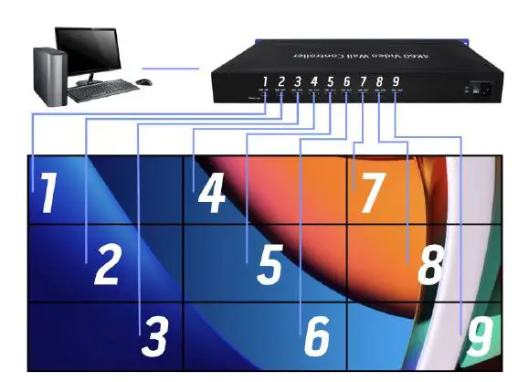
3×6 Video Wall 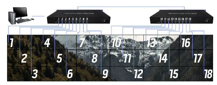
When cascading, the board ID of the 1/2 devices needs to be set: 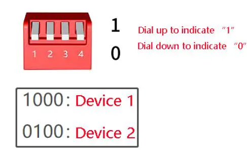
Note: When the devices are cascaded, the image rank (MxN rank) must be the same. 3×9 Video Wall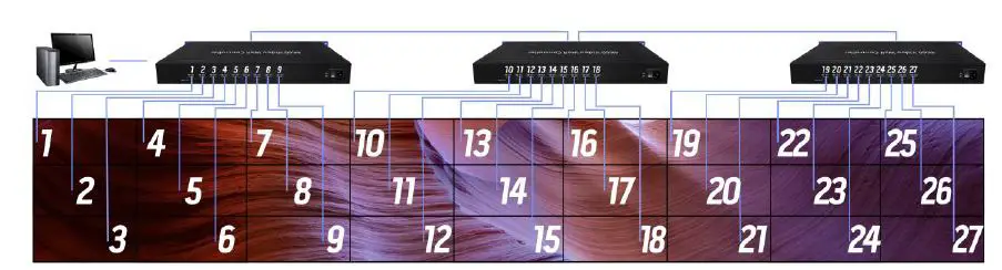
When cascading, the board ID of the 1 / 2 / 3 devices needs to be set: 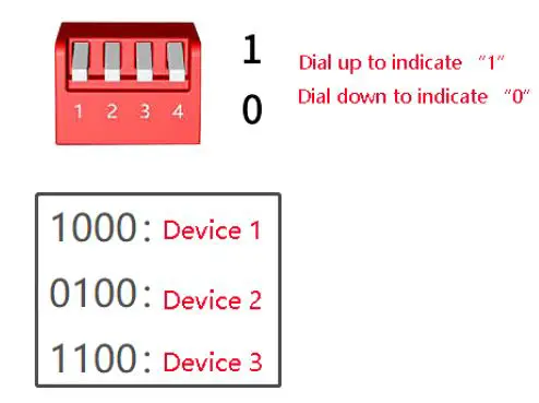
Note: The device cascade setting image (NxM image) must be the same.
Definition of row and column mode: 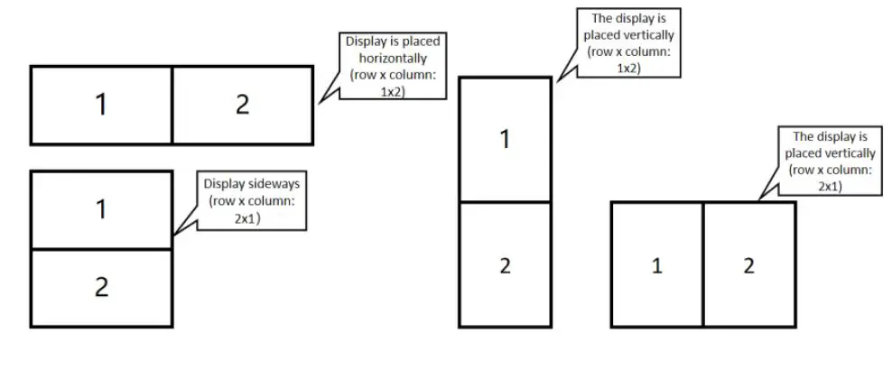
Supported resolution
| Mode | Full screen input resolution | Full screen output resolution | Single screen resolution |
| 1×2 | 3840×1080@30Hz | 3840×1080@60HZ | 1920×1080@60HZ |
| 1×3 | 3840×720@30HZ | 5760×1080@60HZ | 1920×1080@60HZ |
| 1×4 | 4096×576@30HZ | 7680×1080@60HZ | 1920×1080@60HZ |
| 1×5 | 4080×459@30HZ | 9600×1080@30HZ | 1920×1080@60HZ |
| 1×6 | 4032×378@30HZ | 11520×1080@60HZ | 1920×1080@60HZ |
| 1×7 | 4032×324@30HZ | 13440×1080@60HZ | 1920×1080@60HZ |
| 1×8 | 3968×279@30HZ | 15360×1080@60HZ | 1920×1080@60HZ |
| 1×9 | 4032×252@30HZ | 17280×1080@60HZ | 1920×1080@60HZ |
| 9×1 | 784×3969@30HZ | 1920×9720@60HZ | 1920×1080@60HZ |
| 8×1 | 888×3996@30HZ | 1920×8640@60HZ | 1920×1080@60HZ |
| 7×1 | 992×3906@30HZ | 1920×7560@60HZ | 1920×1080@60HZ |
| 6×1 | 1184×3996@30HZ | 1920×6480@60HZ | 1920×1080@60HZ |
| 5×1 | 1408×3960@30HZ | 1920×5400@60HZ | 1920×1080@60HZ |
| 4×1 | 1776×3996@30HZ | 1920×4320@60HZ | 1920×1080@60HZ |
| 3×1 | 1920×3240@30HZ | 1920×3240@60HZ | 1920×1080@60HZ |
| 2×1 | 1920×2160@30HZ | 1920×2160@60HZ | 1920×1080@60HZ |
| 2×2 | 3840×2160@30HZ | 3840×2160@60HZ | 1920×1080@60HZ |
| 2×3 | 3840×1440@30HZ | 5760×2160@60HZ | 1920×1080@60HZ |
| 2×4 | 4096×1152@30HZ | 7680×2160@60HZ | 1920×1080@60HZ |
| 3×2 | 2816×2376@30HZ | 3840×3240@60HZ | 1920×1080@60HZ |
| 3×3 | 3840×2160@30HZ | 5760×3240@60HZ | 1920×1080@60HZ |
| 4×2 | 2688×3024@30HZ | 3840×4320@60HZ | 1920×1080@60HZ |
Table 2 iWall 409R Cascade Mode Supported Resolution
| Mode | Full screen input resolution | Full screen output resolution | Single screen resolution |
| 5×2 | 2336×3285@30HZ | 3840×5400@60HZ | 1920×1080@60HZ |
| 6×2 | 1920×3240@30HZ | 3840×6480@60HZ | 1920×1080@60HZ |
| 7×2 | 2016×3969@30HZ | 3840×7560@60HZ | 1920×1080@60HZ |
| 8×2 | 1776×3996@30HZ | 3840×8640@60HZ | 1920×1080@60HZ |
| 9×2 | 1568×3969@30HZ | 3840×9720@60HZ | 1920×1080@60HZ |
| 2×5 | 4080×918@30HZ | 9600×2160@60HZ | 1920×1080@60HZ |
| 2×6 | 4080×765@30HZ | 11520×2160@60HZ | 1920×1080@60HZ |
| 2×7 | 4088×657@30HZ | 13440×2160@60HZ | 1920×1080@60HZ |
| 2×8 | 4096×576@30HZ | 15360×2160@60HZ | 1920×1080@60HZ |
| 2×9 | 4032×504@30HZ | 17280×2160@60HZ | 1920×1080@60HZ |
| 3×4 | 4096×1728@30HZ | 7680×3240@60HZ | 1920×1080@60HZ |
| 3×5 | 4080×1377@30HZ | 9600×3240@60HZ | 1920×1080@60HZ |
| 3×6 | 4032×1134@30HZ | 11520×3240@60HZ | 1920×1080@60HZ |
| 3×7 | 4032×972@30HZ | 13440×3240@60HZ | 1920×1080@60HZ |
| 3×8 | 4096×864@30HZ | 15360×3240@60HZ | 1920×1080@60HZ |
| 3×9 | 4032×756@30HZ | 17280×3240@60HZ | 1920×1080@60HZ |
| 6×3 | 2640×2970@30HZ | 5760×6480@60HZ | 1920×1080@60HZ |
| 7×3 | 2112×2772@30HZ | 5760×7560@60HZ | 1920×1080@60HZ |
| 8×3 | 2160×3240@30HZ | 5760×8640@60HZ | 1920×1080@60HZ |
| 9×3 | 1728×2916@30HZ | 5760×9720@60HZ | 1920×1080@60HZ |
| 4×4 | 4096×2304@30HZ | 7680×4320@60HZ | 1920×1080@60HZ |
| 4×5 | 4080×1836@30HZ | 9600×4320@60HZ | 1920×1080@60HZ |
| 4×6 | 4032×1512@30HZ | 11520×4320@60HZ | 1920×1080@60HZ |
| 5×5 | 4080×2295@30HZ | 9600×5400@60HZ | 1920×1080@60HZ |
| 2×11 | 4048×414@30HZ | 21120×2160@60HZ | 1920×1080@60HZ |
| 2×12 | 4032×378@30HZ | 23040×2160@60HZ | 1920×1080@60HZ |
| 2×13 | 3952×342@30HZ | 24960×2160@60HZ | 1920×1080@60HZ |
Common problem
- What is the output resolution of the loop-out interface?
Answer: Same as the DisplayPort input resolution of the first device. - Sometimes the dial code or remote control switch does not respond?
Answer: Because it involves resolution switching, it takes a certain time (1s). If the display does not meet the expectations, it can be restored by power off again. - Is there a flash line on screen in cascade mode?
Answer: Please use the DP cable provided by the manufacturer to connect the cascaded DP ports. - There are errors in remote control when cascading: some devices respond to remote control commands normally, and some devices do not respond to remote control commands?
Answer: It is recommended to put the equipment together when using remote control in cascade. - How to recover when an error occurs?
Press the [clone] key, press the key, Return to [output copy mode, input single picture] status, when the cascade device settings are synchronized, continue with other settings.
Appendix: Outputs order
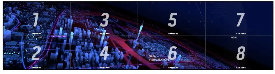
- When the image is not rotated: the output order is from up then down, then from left to right. As shown in the following 2×4 (Row*Col) mode: see below

- When the content is rotated 90ᵒ (anticlockwise): The outputs order is from right to left and then from up to down. As shown in Figure 4×2 mode (Row*Col). see right

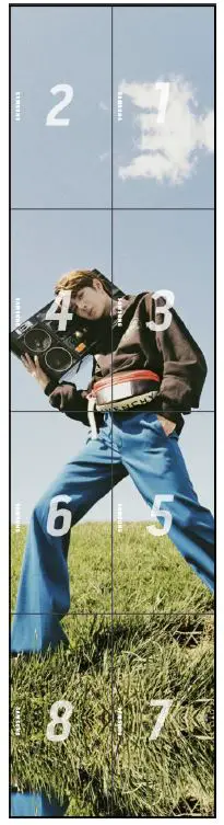
Note*: Please make sure your display direction right the same as the picture shown. The content is rotated by 90ᵒ (anticlockwise), and the
video wall is installed by 90ᵒ clockwise. The “Samsung”logo on the picture is showing the right display direction.


