![]() 4K60 2×2 TV Wall Controller
4K60 2×2 TV Wall Controller
User Manual
Enjoy the vivid world!
Introduction
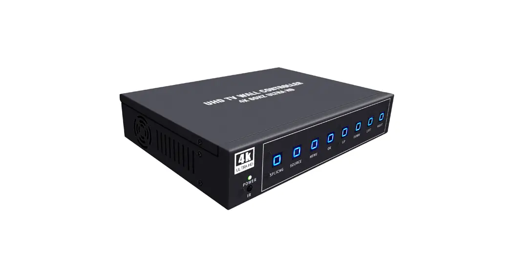
4K60 2×2 tv wall controller
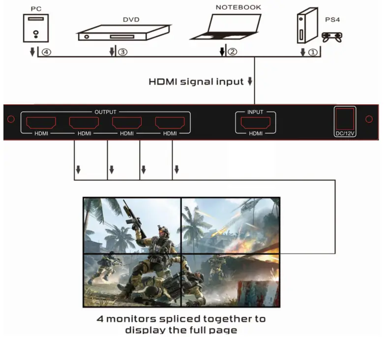
The 2×2 tv wall controller , support 1-way HDMI input and 4 HDMI output, the main function is to divide a complete HDMI,HD image signal into 4 blocks and assign to 4 video display unit (such as Rear projection unit, LCD TV, etc.), Complete with 4 HDMI high-definition video display units to form a large dynamic image screen.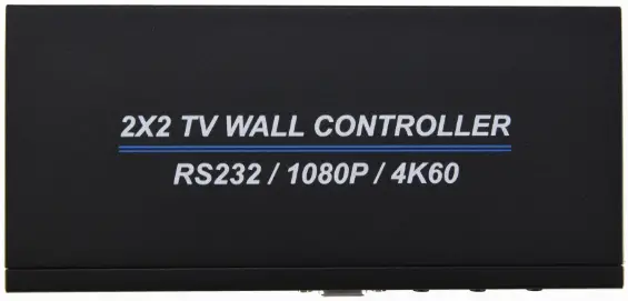
Support modes

Features
- *Support 1 HDMI input
- *Support input HDMI 2.0
- *Support 4 HDMI outputs
- *Support input 4K60HZ,and lower resolution
- *Support output resolution 1920x1080P60
- *Support multiple splicing modes, easy to operate, plug and play
Physical interface diagram
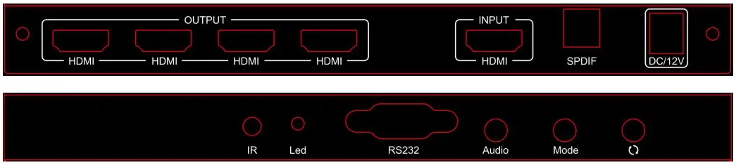
OUTPUT → HDMI Signal Output
INPUT → HDMI Signal Input
SPDIF → Digital Audio Output
DC/12V → Power Adptor Input
IR → Remote Receiver
LED → Power Light
RS232 → RS232 Control
Audio → Audio ON or OFF
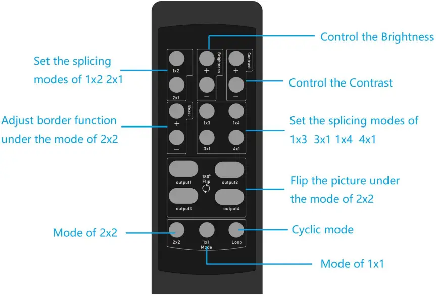
Mode → Different Mode Switch![]() → Flip the picture under the mode of 2×2
→ Flip the picture under the mode of 2×2
Remote controller
Operation steps
STEP 1: Connect hdmi source to hdmi input with HDMI cable,connect hdmi output to TVs.
STEP 2: Connect 12V power adaptor.
STEP 3: Set up splicing mode by the MODE button on the unit or remote controller.
The Package includes
- 2X2 tv wall controller x1
- Power adapter x1
- User Manual x1
Connection operation
RS232 remote control
This product supports RS232 remote command control and returns the status.Connect the RS232 port of the splicer to the PC COM port by a Rs232 uncrossed cable or USB to RS232 adapter. Then install serial port tools in the PC can use RS232 control.
Parameter configuration of serial port on PC side
| Baud rate | 115200 |
| Parity bits | NONE |
| Data bits | 8 |
| Stop bits | 1 |
Serial port command table:
| NO | Send command | Return | |||
| ASCII | HEX | Instruction | Successful | Failul | |
| 1 | !SwO# | 0x21 0x53 0x57 0x30 0x23 | Switch to OFF mode | !RcO# | NON E |
| 2 | !Sw1# | 0x21 0x53 0x57 0x31 0x23 | Switch to 1X1 Spliced mode | iRc1# | NON E |
| 3 | !Sw2# | 0x21 0x53 0x57 0x32 0x23 | Switch to 2X2 Spliced mode | iRc2# | NON E |
| 4 | !Sw3# | 0x21 0x53 0x57 0x33 0x23 | Switch to 1X2 Spliced mode | iRc3# | NON E |
| 5 | !Sw4# | 0x21 0x53 0x57 0x34 0x23 | Switch to 1X3 Spliced mode | I Rc4# | NON E |
| 6 | !Sw5# | 0x21 0x53 0x57 0x35 0x23 | Switch to 1X4 Spliced mode | iRc5# | NON E |
| 7 | !Sw6# | 0x21 0x53 0x57 0x36 0x23 | Switch to2X1 Spliced mode | IRc6# | NON E |
| 8 | !Sw7# | 0x21 0x53 0x57 0x37 0x23 | Switch to3X1 Spliced mode | iRc7# | NON E |
| 9 | !Sw8# | Ox21 Ox53 Ox57 Ox38 0x23 | Switch to4X1 Spliced mode | I Rc8# | NON E |
| 10 | !Sw9# | 0x21 0x53 0x57 0x39 0x23 | Backward loop switch mode | !RCX#(X:0-8) | NON E |
| 11 | !SWA# | 0x21 0x53 0x57 0x41 0x23 | Forward loop switch mode | !RCX#(X:0-8) | NON E |
| 12 | !SWB# | 0x21 0x53 0x57 0x42 0x23 | Standby | !RcB# | NON E |
| 13 | !SWC# | 0x21 0x53 0x57 0x43 0x23 | Power on | !RcC# | NON E |
| 14 | !SWD# | 0x21 0x53 0x57 0x44 0x23 | Turn on the OSD show | !RcD# | NON E |
| 15 | !SWE# | 0x21 0x53 0x57 0x45 0x23 | Turn off the OSD show | !RcE# | NON E |
| 16 | !COM# | 0x21 Ox43 Ox4f Ox4d 0x23 | Reads current state | Power state/ OSD state/ Display mode e.g.!RCC#! RCE#!RC2# | NON E |
![]()


