infobit iWall X404 Video Wall Controller
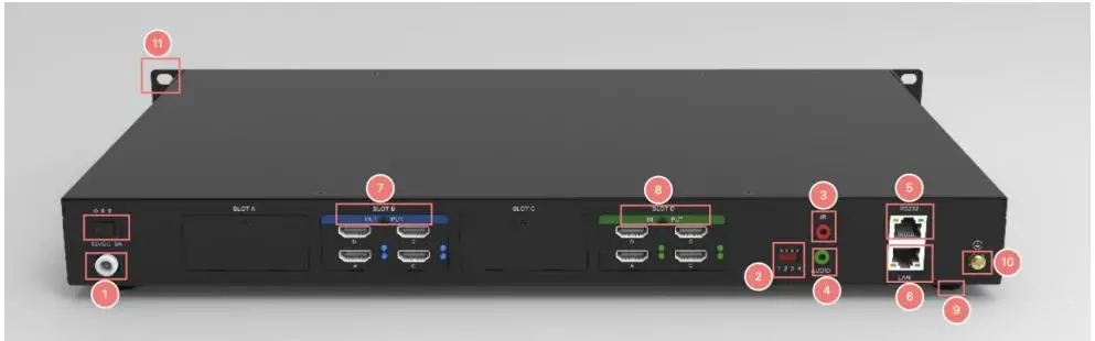
Interface Introduction
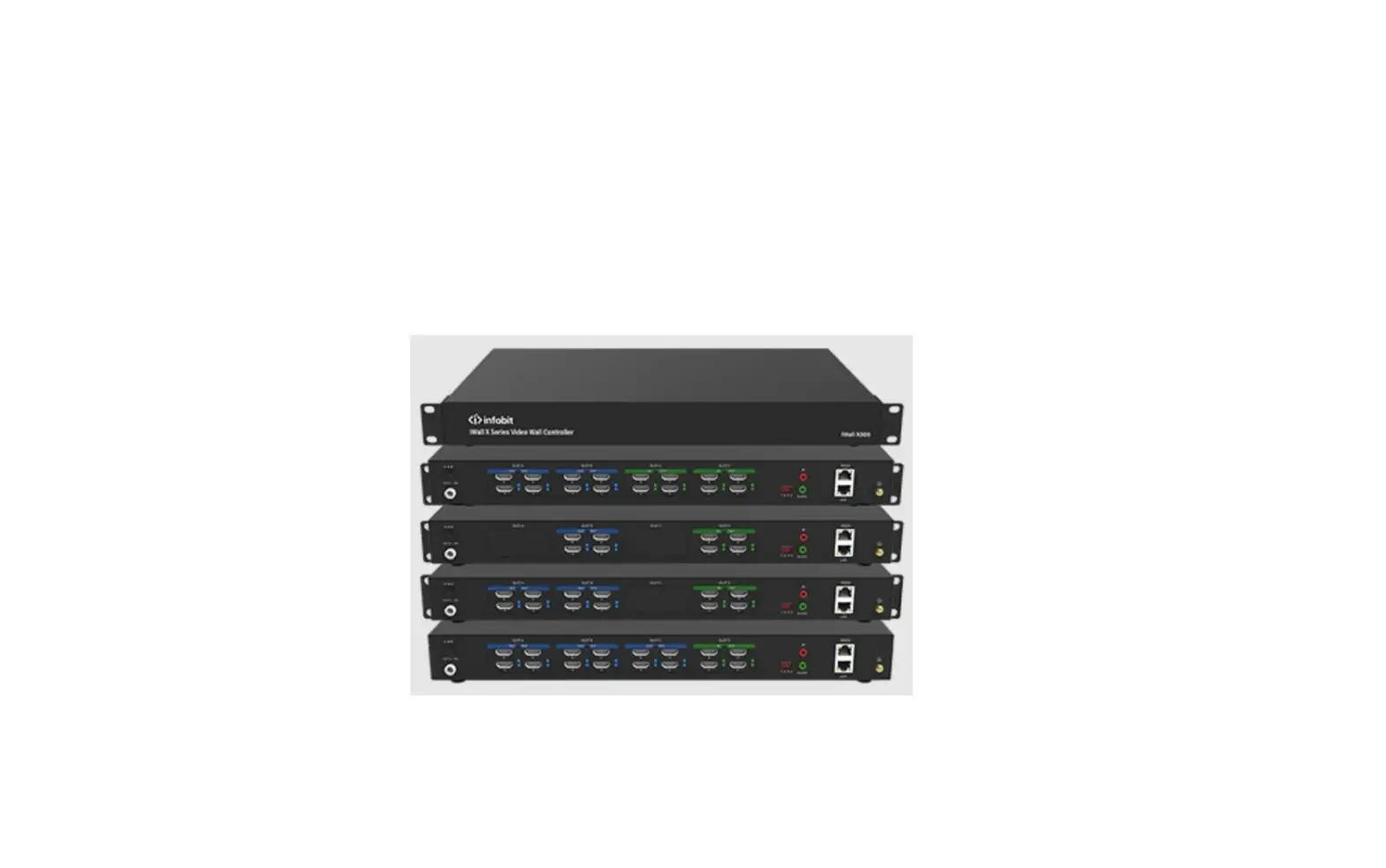
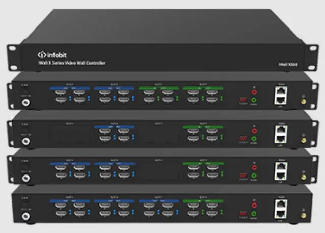
Model: iWall X404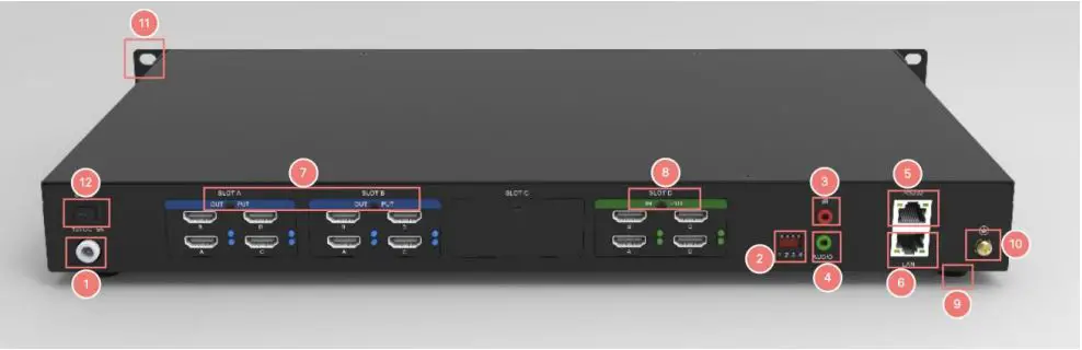
Model: iWall X408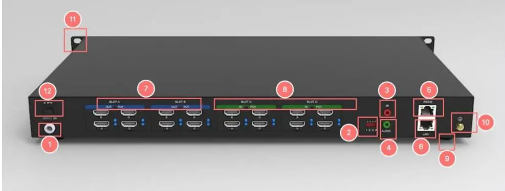
Model: iWall X808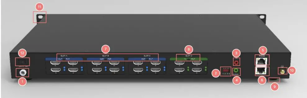
Model: iWall X412
| No. | Description |
| 1 | 12V Power supply |
| 2 | Dial switch |
| 3 | IR receiver (Reserved for future) |
| 4 | Audio Out (3.5mm) |
| 5 | RS232 |
| 6 | 10/100M LAN |
| 7 | HDMI output (Blue light) |
| 8 | HDMI input (Green light) |
| 9 | Chassis foot pad |
| 10 | GND |
| 11 | Handle |
| 12 | Power switch |
Features
- Advanced CrossBar technology
- Robust FPGA video data process technology
- No PC vulnerabilities
- 1 to 12 display outputs
- 4x video overlay windows per display
- Video windows zoom in, zoom out, moving, overlay, roaming, resizing and switching
- With 4×4, 4×8, 4×12 and 8×8 HD graphics inputs and outputs
- Low power consumption
- Low capture & display latency
- Support both LCD and LED videowall
- Presets saving and auto switching
- Video cropping
- Scrolling text*
- Embedded HDMI audio in all inputs
- 1x de-embedded audio from any input
- One-touch audio switching, mute or unmute
- Drag-and-Drop software operation
- One-touch Power On/ Off the whole videowall
- Seamless switching without any blank intervals
- Both videowall and matrix mode
- TCP/IP, RS232 Control
- Multiple user levels management
- Background picture
Spec
| Series | iWall X | |||
| Name | 1080P HDMI Video Wall Controller | |||
| Models | iWall X404 | iWall X408 | iWall X808 | iWall X412 |
| Video Inputs | 4x HDMI | 4x HDMI | 8x HDMI | 4x HDMI |
| Video Outputs | 4x HDMI | 8x HDMI | 8x HDMI | 12x HDMI |
| HDMI version | HDMI 1.3 | |||
| HDMI distance | 15 meters via good quality copper cable | |||
| HDCP version | Not support HDCP | |||
| Size | 1U | |||
| I/O resolutions | Max. 1920×1080 60Hz, support customize resolutions | |||
| Audio Inputs | Embedded HDMI audio in all inputs | |||
| Audio Outputs | 1x 3.5mm de-embedded audio from any input, stereo 192K sampling rate, 32bit | |||
| Video windows | 4x video overlay windows per display zoom in, zoom out, moving, overlay, roaming, resizing and switching | |||
| Presets | Saving and auto switching | |||
| Video Cropping | Support | |||
| LCD videowall | Support | |||
| LED videowall | Support | |||
| Seamless Switching | Support | |||
| Operating System | FPGA pure hardware architecture, no OS | |||
| Videowall and Matrix | Supports both Videowall and Matrix modes | |||
| OSD text | Fixed OSD text* (the scrolling feature will be ready in Q3, 2023) | |||
| Background picture | Support | |||
| Control | TCP/IP, RS232 Control | |||
| Software | Windows PC, Android tablet | |||
| Net Dimension WHD | 44*6*25 cm without Ear, 48.5*6*25 cm with Ear | |||
| Gross Dimension WHD | 605*165*455 cm | |||
| Net Weight | 2.5kg | 2.6kg | 2.7kg | 2.7kg |
| Gross Weight | 5.1kg | 5.2kg | 5.2kg | 5.2kg |
| Power | In: 110-240V, 50/60Hz. Out: 12V DC 5A, 60W | |||
| In package | 1x iWall X; 1x Power adapter; 1x UK power cord; 1x EU power cord; 1x 3.5mm audio cable, 1x RS232 to RJ45 adapter; 1x Grounding cable | |||
Wiring instructions
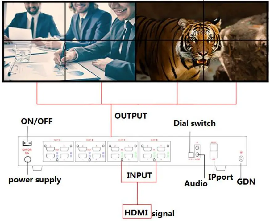
- Connect the HDMI video cable, power supply, network cable, audio cable, and ground line.
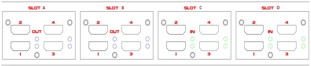
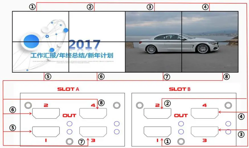
- Each card slot of the controller is printed with “SLOT A, SLOT B, SLOT C, SLOT D…”, the slots are arranged in alphabetical order, and each one is printed with “IN” and “OUT”, it can also be distinguished according to the color of the indicators. The green one is input (IN) and the blue is output (OUT) as shown in the following figure:

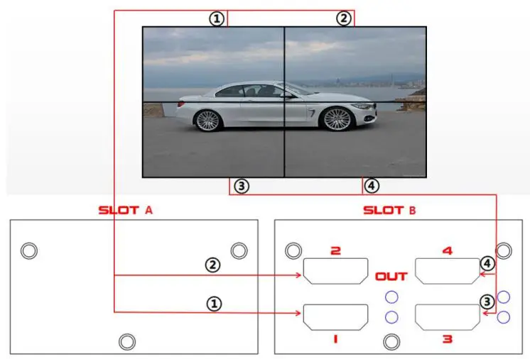
- The output cables to the LCD videowall must correspond to the output port sequence of the iWall X video wall controller, as shown in the figure below:
*Note: the SLOT B (to LCD 1-4) is prior to the SLOT A (to LCD 5-8) for a 2×2 videowall.
2*2 videowall diagram
2*4 videowall diagram - The iWall X also support LED wall. The output cables to the LED sending cards must correspond to the output port sequence of the iWall X video wall controller, same as LCD connections.
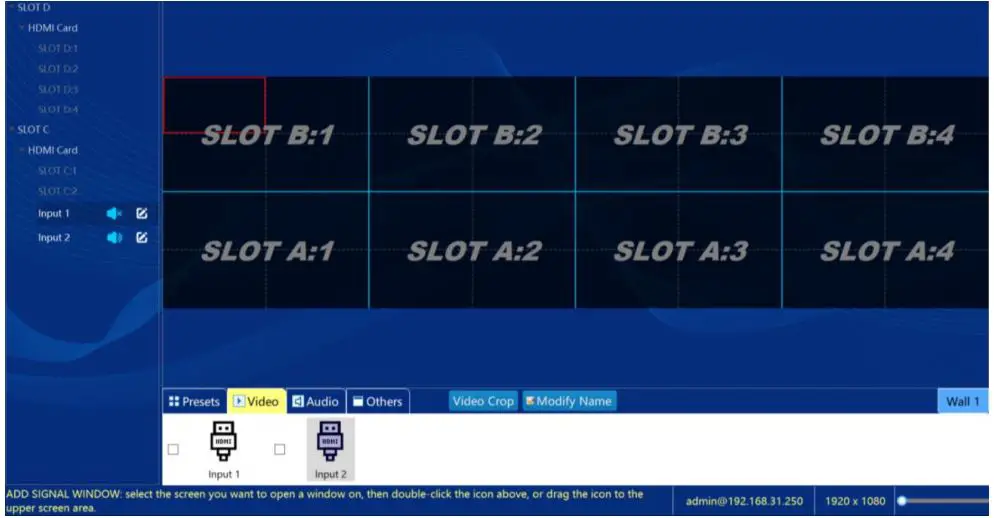
- Connect the software (see Paragraph 5), after setting the screen output (see Paragraph 7), the wiring sequence of the outputs will be shown on the virtual screen area on the iWall X software; follow this sequence to connect the videowall to the iWall X controller. For example, as below: the SLOT B: 1, 2, 3 and 4 to be connected to LCD 1-4; the SLOT A: 1, 2, 3 and 4 to be connected to LCD 5-8;


Install the iWall X software
Copy the client software installation package iWall 3.2.7 setup to the computer, and then double-click the file and click next to complete the installation.
IP setting
Connect the controller and the computer directly with a network cable or connect both to the same switch or router. The factory IP address of the controller is 192.168.1.250, and the computer IP must be set to 192.168.1.xx to make sure they are under the same LAN.
To change the default IP of the video wall controller, please refer paragraph 14. Change IP Address
Software connection
Open the iWall X, click Connect, enter the controller IP Address, User Name (admin as default), and the password are empty; you can also select the auto-searched IP (see the figure below) and click Ok to login.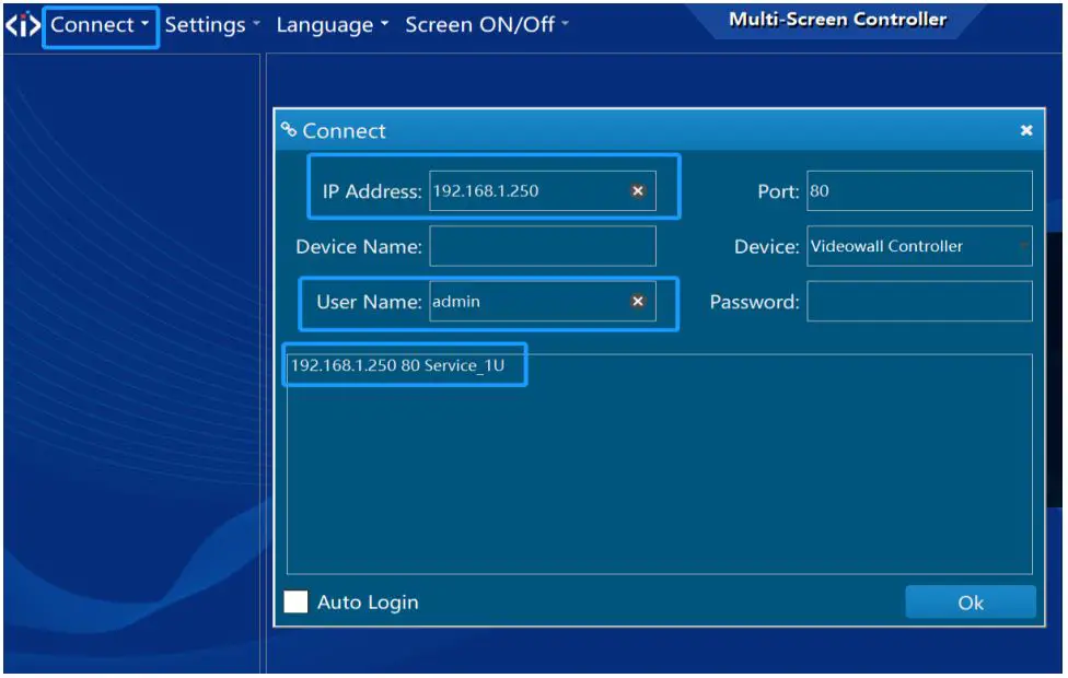
Device activation
After logging in to the software, at the first time the device needs to be activated, the temporary activation code is :888888; after activation, the information can be viewed in the Settings- About menu. See below: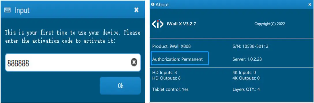
Switching languages
Click Language to switch between Simplified Chinese, Traditional Chinese, and English as shown below: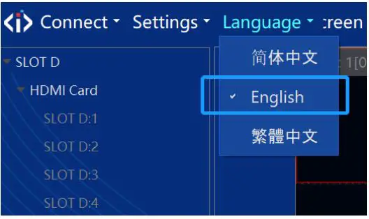
Settings
LCD Videowall settings
Click Settings–>Videowall, if the displays are a LCD, DLP and other standard resolution screens, you need to set the screen resolution of the iWall X output, see figure below: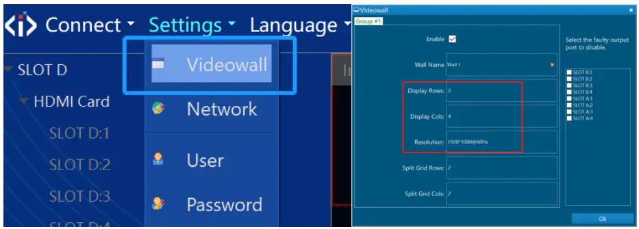
The Split Grid Rows and Cols means the virtual splitting grids on each LCD display, it can be used to open video windows at the right position and aspect ratio.
LED wall settings
Click Settings–>Videowall->Resolution->Custom Resolution, if the displays are a LED, you need to set the custom screen resolution of the iWall X output for the sending cards, see figure below: (The Display Rows means sending cards rows, and the Display Cols means sending cards cols.)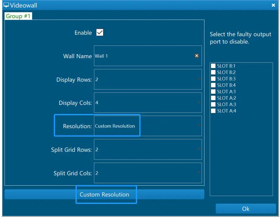
The Split Grid Rows and Cols means the virtual splitting grids on each sending card, it can be used to open video windows at the right position and aspect ratio.
Click the number in the first row to select a column, you can adjust the display width.
Click the number on the left to select a row, you can adjust the display height. As below: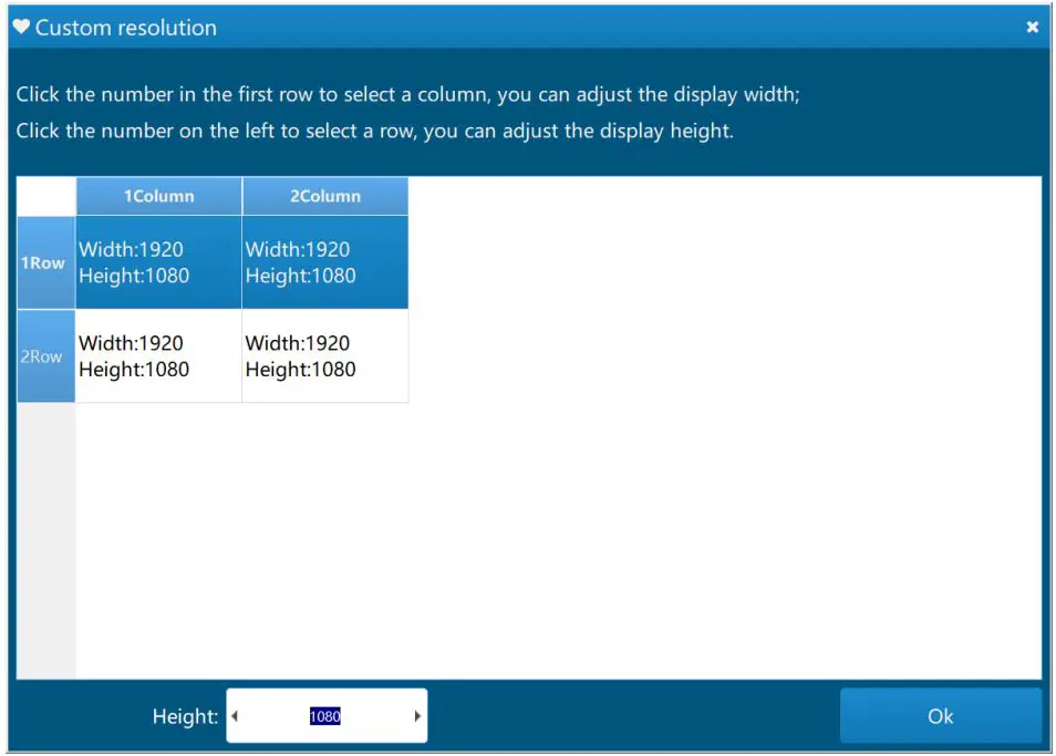
Source management
- Connect the signal source to the input ports, and the signals can be automatically identified.
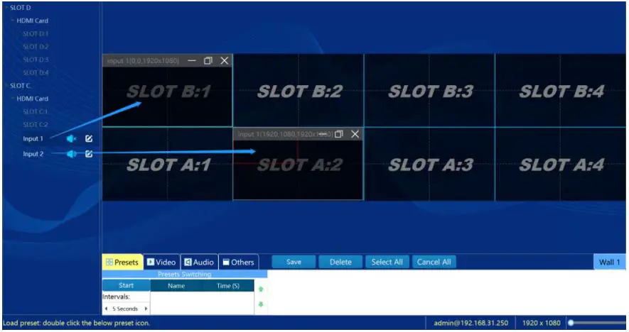
- There are two ways to dray the source to the videowall.
- Double-click the signal source or drag the signal source to the specified window position, as shown in the figure below:

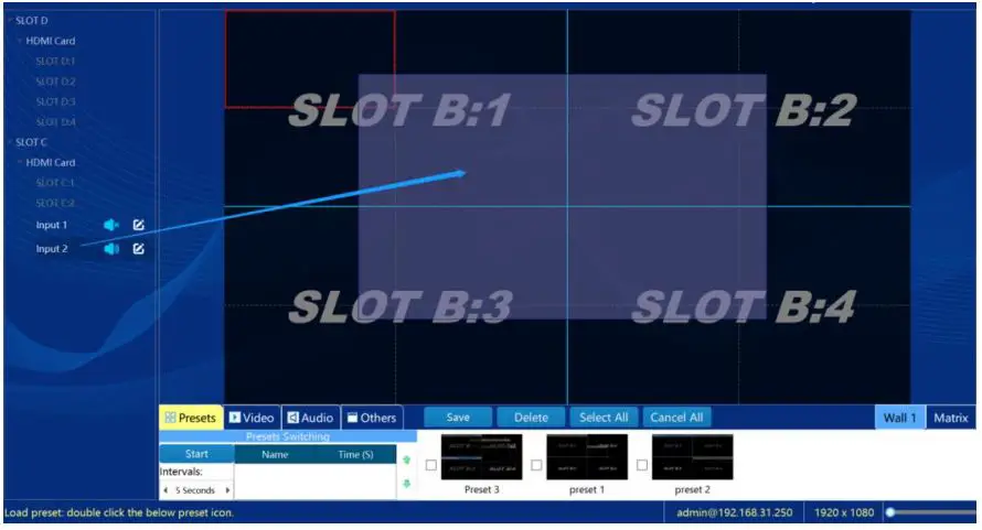
- Select one input signal, then drag any rectangle on the right virtual videowall area. As below:

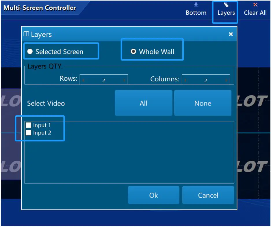
- Click on the Layers button, choose to open the window on a single selected screen or the whole wall. As shown below:

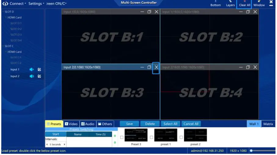
Video window management
- Click
 on the right-up corner, close the current source. Click Clear All button to quickly close all the windows. As shown below:
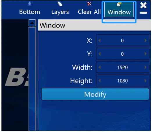
- The source position, zoom in and zoom out can be realized by the mouse. It also can be realized by changing the parameter value of the window property by clicking the Window button; as shown in the figure below:

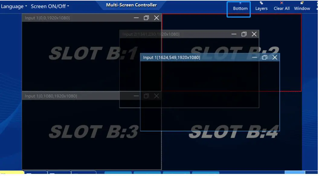
- When the current layer is selected by the mouse, the current layer is placed on top; when click Bottom button, the layer can be sent to bottom. As shown below:

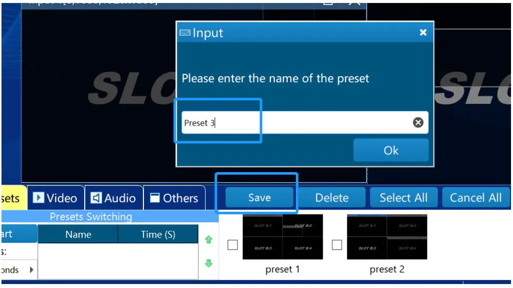
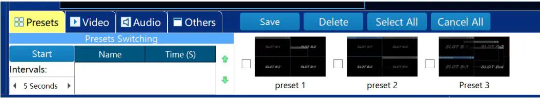
Preset
- After the window layers are set up, click the Save button, enter the name of the preset, and click OK, as shown in the figure below:

- The saved presets can be viewed in the below list, as shown in the figure below:

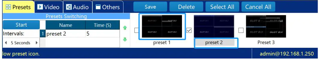
- Switch presets: double-click the name or the corresponding thumbnail to quickly switch.

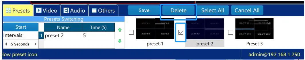
- Delete preset: select the preset and click Delete button.

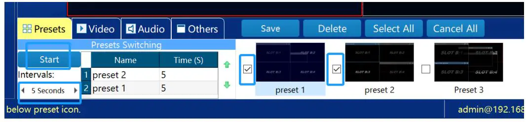
- Presets auto switching: select the presets you want to switch and setup the switching time interval, then click Start button to enable.

Audio switching
Click the audio sign to mute or unmute the sound, as shown in the figure below: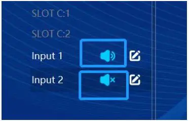
There is only one input signal can be enabled with audio and routed to the 3.5mm output at the rear panel of iWall X. When turn on audio for one input signal, the other audio channels from other inputs will be muted automatically.
Background image
Click on the Others->Change Pic buttons to modify the background image and select the image in the computer.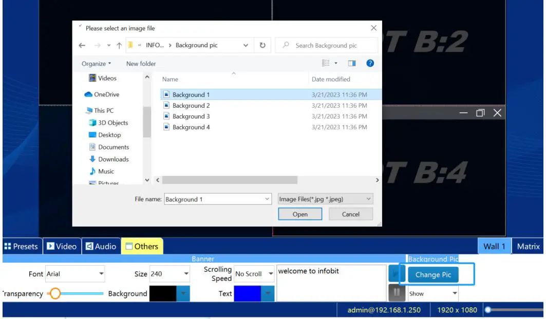
Change IP address
Click Settings->Network to modify the current IP, Subnet Mask, and Gateway of the videowall controller.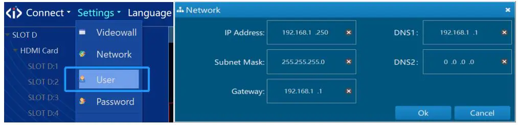
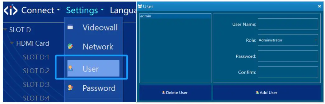
User management and password
- Click Settings->User, enter the Username and Password, click Add User or Delete User to manage.

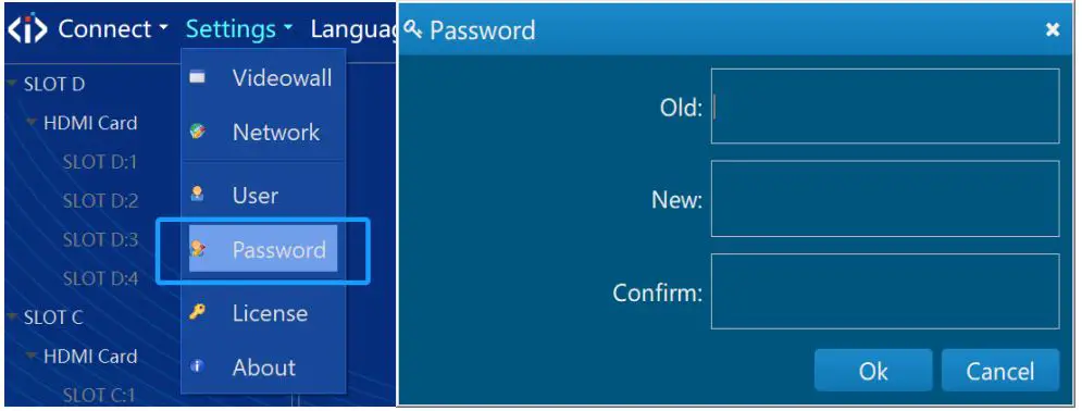
- Click Settings->Password to modify the current account password, as shown in the figure below:

License
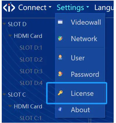
- Click Settings->License to select the authorization file to import.

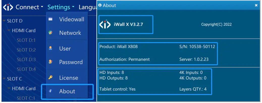
- Click Settings->About, you can check whether the authorization information is correct, and check the software version, product model, serial number, etc.

Screen ON/Off
Connect the videowall and controller with serial cable, set the Screen ON/Off in the software; set the serial port and commands.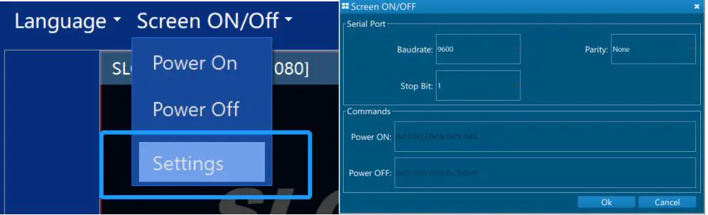
Input
Crop the input
Select the input source, click the Video Crop button to cut the input images to fit the suitable aspect ratio or cut off the black edges.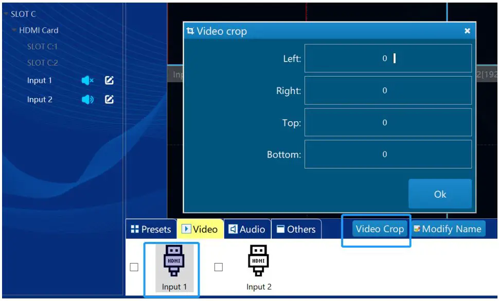
Rename the input
Select the name of the signal source, click the Rename icon then enter a new name. As shown below: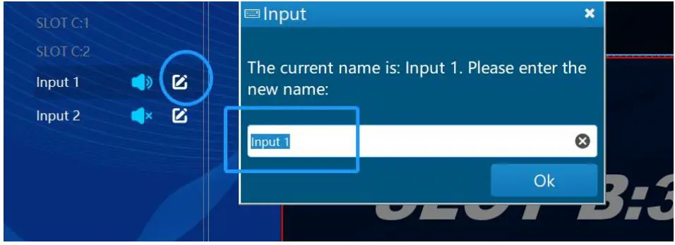
App control
Install the Android app on the tablet or mobile phone, make sure the WIFI connected to the tablet or mobile phone must be in the same network segment as the controller; open the APP, enter the controller’s IP address, username (admin as default), and password to be empty as default, and log in. You can also log in with the username and password created by the client. After successful login, the APP control interface appears. As shown below: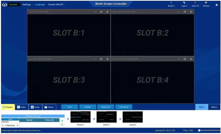
Click the Video button to select inputs and drag-and-drop to the videowall area. Or double click any preset to enable the video layers layout. Other operations are the same as Windows PC version software.
Central Control
Connect method.
The system supports HTTP and RS232 serial port.
Baud rate: 9600
Parity: none
Bit: 8
Stop: 1
Package
The commands sent by the central control to the device and the responses sent by the device to the central control are all encapsulated into data packets. Each data packet starts with the $ character and ends with the ^, as shown in the following figure:
Op represents an operation command, one character.
Scr represents the screen group number to be operated, one character. For iWall X, it is 1 (the iWall X 1U doesn’t support multiple video wall groups)
| $ | Op | Scr | DATA | ^ |
Serial Command
- Get the Preset list
Op 1 Scr One byte, values 1 to 4, specifying the video wall group number DATA No Application sample Get videowall group One Preset: $11^ Get videowall group Two Preset: $12^ Get videowall group Three Preset: $13^ Get videowall group Four Preset: $14^
- Equipment response:
Op 3 Scr One byte, values 1 to 4, specifying the video wall group number
DATA Name of preset (UTF8 format) Application sample Switch screen group one “preset five”: $31 preset five^ Switch screen group two “preset ab”: $32 ab^ Switch screen group three “preset 123ab”: $33123 ab ^ Switch screen group four “preset 6a”: $34 preset 6a ^
Preset Name “1” Code:24 33 31 31 5E
Preset Name “2” Code:24 33 31 32 5E Preset Name “3” Code:24 33 31 33 5E
Equipment response:
Op 3 DATA Ok or Error - Gets the controller IP
Op 6 Scr No DATA No Application sample
$6^ Equipment response:
Op 6 DATA Controller IP. Ror instance: IP:[192.168.1.250]
- Sets the controller IP address.
Op 7 Scr No DATA IP address Application Set the Address IP 192.168.1.200: $7192.168.1.200^ sample Equipment response:
Op 7 DATA Ok or Error
Attention
To ensure the reliable use of equipment and the safety of personnel, in the installation, using, and maintenance, please comply with the following:
- When the equipment is installed, make sure the controller is well grounded.
- Do not place the equipment in an overheated and under-cooled place.
- Maintain good ventilation in the working environment to facilitate the timely discharge of heat from the equipment to avoid excessive temperature damage to the equipment.
- In wet dew environment or long-term non-use, the total power supply of the equipment should be turned off.
- Be sure to unplug the AC power cord from the power outlet before:
- Remove or reinstall any part of the equipment.
- Do not disassemble the equipment without permission, to avoid the danger of electric shock. Do not repair privately, lest aggravate the damage degree of equipment.


