OMRON Safety Relay G7SA Installation Guide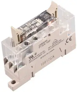
For pricing and availiablity in your local county please visit one of the below link
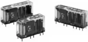
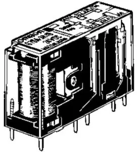
Safety Relay
Slim Safety Relays Conforming to EN Standards
- The forcibly guided contact in the G7SA assures safe operation (EN50205 Class A, approved by VDE.)
- Ideal for use in safety circuits in press machinery, machine tools, and other production machinery.
- Four-pole and six-pole Relays are available.
- The Relay’s terminal arrangement simplifies PWB pattern design.
- Reinforced insulation between inputs and outputs. Reinforced insulation between some poles.
- UL, CSA approval.
- CE marking.


Note: Be sure to refer to the Precautions.

Ordering Information
Safety Relays
| Type | Sealing | Poles | Contacts | Rated voltage | Model |
| Standard | Flux-tight | 4 poles | 3PST-NO, SPST-NC | 24 VDC | G7SA-3A1B |
| DPST-NO, DPST-NC | G7SA-2A2B | ||||
| 6 poles | 5PST-NO, SPST-NC | G7SA-5A1B | |||
| 4PST-NO, DPST-NC | G7SA-4A2B | ||||
| 3PST-NO, 3PST-NC | G7SA-3A3B |
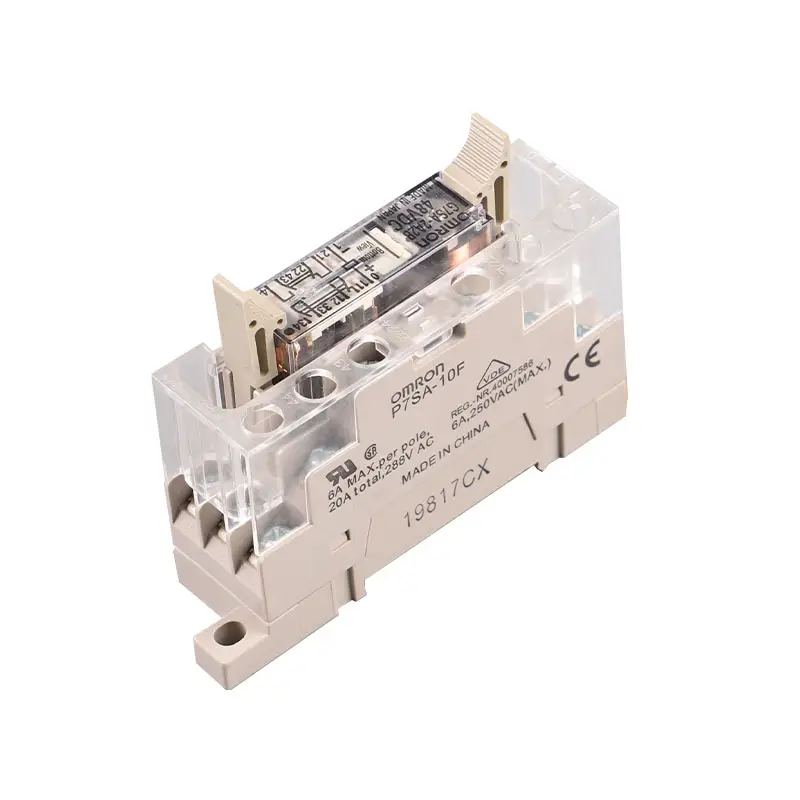
Safety Relay Sockets
| Type | LED indicator | Poles | Rated voltage | Model | |
| Track-mounting | Track mounting and screw mounting possible | No | 4 poles | — | P7SA-10F |
| 6 poles | P7SA-14F | ||||
| Yes | 4 poles | 24 VDC | P7SA-10F-ND | ||
| 6 poles | P7SA-14F-ND | ||||
| Back-mounting | PCB terminals | No | 4 poles | — | P7SA-10P |
| 6 poles | P7SA-14P | ||||
Model Number Legend
G7SA-☐A☐B
- NO Contact Poles
- DPST-NO
- 3PST-NO
- 4PST-NO
- 5PST-NO
NC Contact Poles
- SPST-NC
- DPST-NC
- 3PST-NC
Specifications
Ratings
Coil
Rated voltage | Rated current | Coil resistance | Must-operate voltage | Must-release voltage | Max. voltage | Power consumption |
| 24 VDC | 4 poles: 15 mA 6 poles: 20.8 mA | 4 poles: 1,600 W 6 poles: 1,152 W | 75% max. (V) | 10% min. (V) | 110% (V) | 4 poles: Approx. 360 mW 6 poles: Approx. 500 mW |
Note:
- The rated current and coil resistance are measured at a coil temperature of 23°C with tolerances of ±15%.
- Performance characteristics are based on a coil temperature of 23°
- The value given for the maximum voltage is for voltages applied instantaneously to the Relay coil (at an ambient temperature of 23°C) and not
Contacts
| Load | Resistive load (cos f =1) |
| Rated load | 6 A at 250 VAC, 6 A at 30 VDC |
| Rated carry current | 6 A |
| Max. switching voltage | 250 VAC, 125 VDC |
| Max. switching current | 6 A |
| Max. switching capacity (reference value) | 1,500 VA, 180 W |
Characteristics
Safety Relay Sockets
| Model | Continuous current | Dielectric strength | Insulation resistance |
| P7SA-14☐ | 6 A (see note 1) | 2,500 VAC for 1 min. between poles | 100 MW min. (see note 2) |
Note:
- If the P7SA-1☐F is used between 55 and 85°C, reduce the continuous current (from 6A) by 0.1 A for every degree.
- Measurement conditions: Measurement of the same points as for the dielectric strength at 500
- When using the P7SA-1☐F-ND at 24 VDC, use at an ambient operating temperature from –25 to 55°
Safety Relays
| Contact resistance | 100 mW max. (The contact resistance was measured with 1 A at 5 VDC using the voltage-drop method.) | |
| Operating time (see note 2) | 20 ms max. | |
| Response time (see note 2) | 10 ms max. (The response time is the time it takes for the normally open contacts to open after the coil voltage is turned OFF.) | |
| Release time (see note 2) | 20 ms max. | |
| Maximum operating frequency | Mechanical | 36,000 operations/hr |
| Rated load | 1,800 operations/hr | |
| Insulation resistance | 100 MW min. (at 500 VDC) (The insulation resistance was measured with a 500-VDC megger at the same places that the dielectric strength was measured.) | |
| Dielectric strength (see notes 3, 4) | Between coil contacts/different poles: 4,000 VAC, 50/60 Hz for 1 min (2,500 VAC between poles 3–4 in 4-pole Relays or poles 3–5, 4–6, and 5–6 in 6-pole Relays.) Between contacts of same polarity: 1,500 VAC, 50/60 Hz for 1 min | |
| Vibration resistance | 10 to 55 Hz, 1.5-mm double amplitude | |
| Shock resistance | Destruction | 1,000 m/s2 |
| Malfunction | 100 m/s2 | |
| Life expectancy | Mechanical | 10,000,000 operations min. (at approx. 36,000 operations/hr) |
| Electrical | 100,000 operations min. (at the rated load and approx. 1,800 operations/hr) | |
| Min. permissible load (see note 5) (reference value) | 5 VDC, 1 mA | |
| Ambient temperature (see note 6) | Operating: –40°C to 85°C (with no icing or condensation) Storage: –40°C to 85°C (with no icing or condensation) | |
| Ambient humidity | Operating: 35% to 85% Storage: 35% to 85% | |
| Weight | 4 poles: Approx. 22 g 6 poles: Approx. 25 g | |
| Approved standards | EN61810-1 (IEC61810-1), EN50205, UL508, CSA22.2 No. 14 | |
Note
- The values listed above are initial values
- These times were measured at the rated voltage and an ambient temperature of 23° Contact bounce time is not included.
- Pole 3 refers to terminals 31–32 or 33–34, pole 4 refers to terminals 43–44, pole 5 refers to terminals 53–54, and pole 6 refers to terminals 63–64.
- When using a P7SA Socket, the dielectric strength between coil contacts/different poles is 2,500 VAC, 50/60 Hz for 1
- permissible load is for a switching frequency of 300 operations/min.
- When operating at a temperature between 70°C and 85°C, reduce the rated carry current (6 A at 70°C or less) by 1 A for each degree above 70°C.
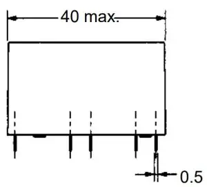
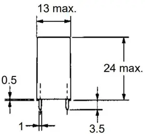
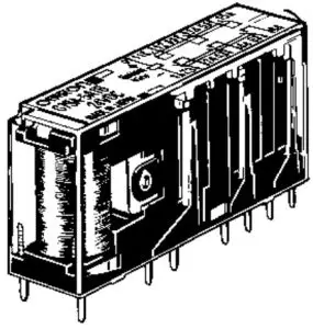
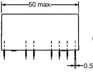
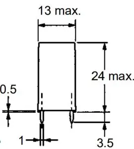
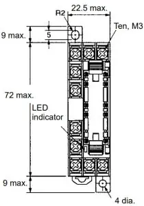
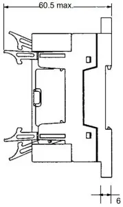
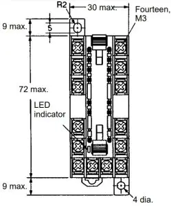
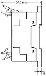
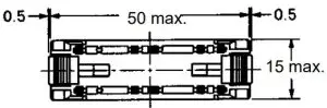
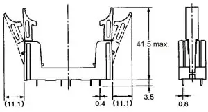
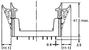
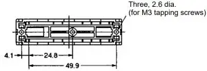
Dimensions
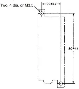
Note: All units are in millimeters unless otherwise indicated. The diagrams are drawn in perspective.
Safety Relays
G7SA-3A1B
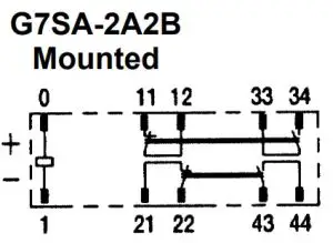
G7SA-2A2B
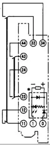
Terminal Arrangement/ Internal Connection Diagram (Bottom View)
G7SA-3A1B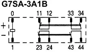
G7SA-2A2B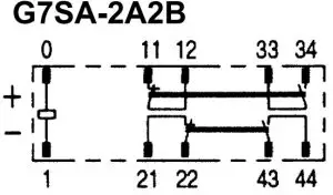
Note: Terminals 23-24, 33-34, and 43-44 are normally open. Terminals 11-12 and 21-22 are normally closed.
G7SA-5A1B
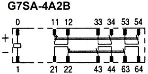
G7SA-4A2B
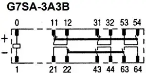
G7SA-3A3B
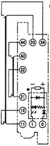
Terminal Arrangement/ Internal Connection Diagram (Bottom View)
G7SA-5A1B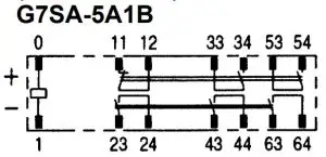
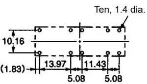
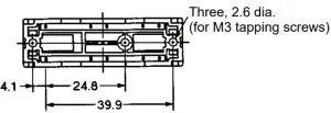
Printed Circuit Board Design Diagram (Bottom View)
(±0.1 tolerance)
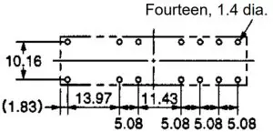
Note: Terminals 23-24, 33-34, 53-54, and 63-64 are normally open. Terminals 11-12, 21-22, and 31-32 are normally closed.
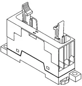
Safety Relay Sockets
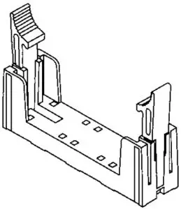
Track-mounting Socket
P7SA-10F, P7SA-10F-ND
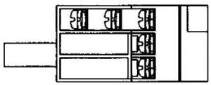
Terminal Installation/Internal Connection Diagram (Top View)
This display circuit is available only for “-ND” models.
Note: Terminals 23-24, 33-34, and 43-44 are normally open. Terminals 11-12 and 21-22 are normally closed.
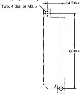
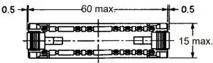
Mounting Hole Placement Diagram (Top View)
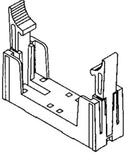
Track-mounting Socket P7SA-14F, P7SA-14F-ND
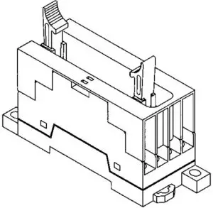
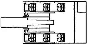
Note: The socket is shown with the finger cover removed.
Note: Only the -ND Sockets have LED indicators.
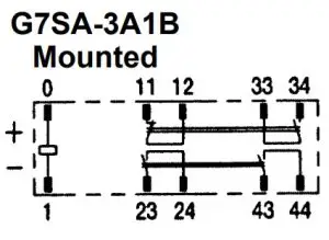
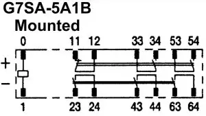
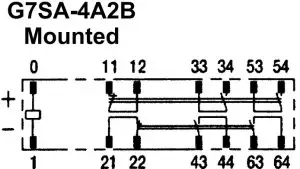
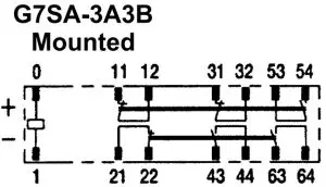
Terminal Arrangement/Internal Connection Diagram (Top View)
G7SA-5A1B Mounted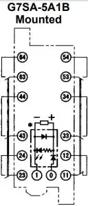
G7SA-4A2B Mounted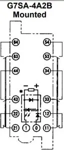
G7SA-3A3B Mounted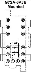
Mounting Hole Placement Diagram (Top View)
* This display circuit is available only for “-ND” models.
Note: Terminals 23-24, 33-34, 43-44, 53-54, and 63-64 are normally open. Terminals 11-12, 21-22, and 31-32 are normally closed.
P7SA-10P Back-mounting Socket (for PCB)
Terminal Arrangement/Internal Connection Diagram (Bottom View)
Mounting Hole Placement (Bottom View)
(±0.1 tolerance)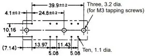
Note: Terminals 23-24, 33-34, and 43-44 are normally open. Terminals 11-12 and 21-22 are normally closed.
P7SA-14P Back-mounting Socket (for PCB)
Terminal Arrangement/Internal Connection Diagram (Bottom View)
Mounting Hole Placement (Bottom View)
(±0.1 tolerance)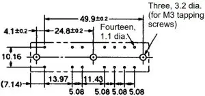
Note: Terminals 23-24, 33-34, 43-44, 53-54, and 63-64 are normally open. Terminals 11-12, 21-22, and 31-32 are normally closed.
Precautions
Safety Relays
A Safety Relay is a Relay with which a safety circuit can be configured.
Wiring
Use one of the following wires to connect to the P7SA 10F/10FND/14F/14F-ND.
Stranded wire: 0.75 to 1.5 mm2
Solid wire: 1.0 to 1.5 mm2
Tighten each screw of the P7SA-10F/10F-ND/14F/14F-ND to a torque of 0.98 N m securely.
Wire the terminals correctly with no mistakes in coil polarity, otherwise the G7SA will not operate
Cleaning
The G7SA is not of enclosed construction. Therefore, do not wash
the G7SA with water or detergent.
Forcibly Guided Contacts (from EN50205)
If an NO contact becomes welded, all NC contacts will maintain a minimum distance of 0.5 mm when the coil is not energized. Likewise if an NC contact becomes welded, all NO contacts will maintain a minimum distance of 0.5 mm when the coil is energized
ALL DIMENSIONS SHOWN ARE IN MILLIMETERS.
To convert millimeters into inches, multiply by 0.03937. To convert grams into ounces, multiply by 0.03527
![]()
![]()
![]()


