![]()


http://www.seneca.it/products/s91
INSTALLATION MANUAL
S91 / S91-400
Multi-protection relay for motors
MI00536-5
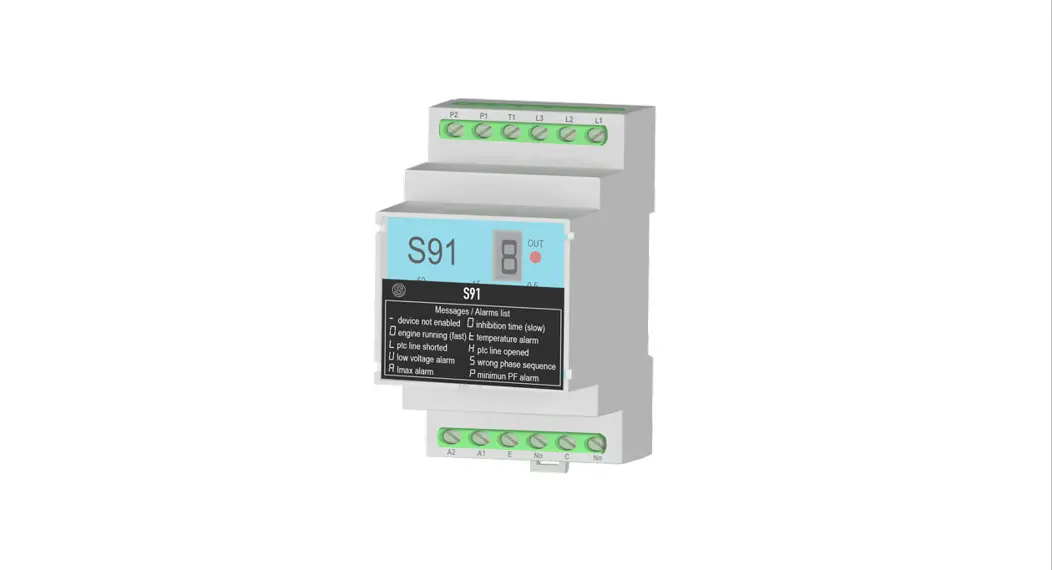
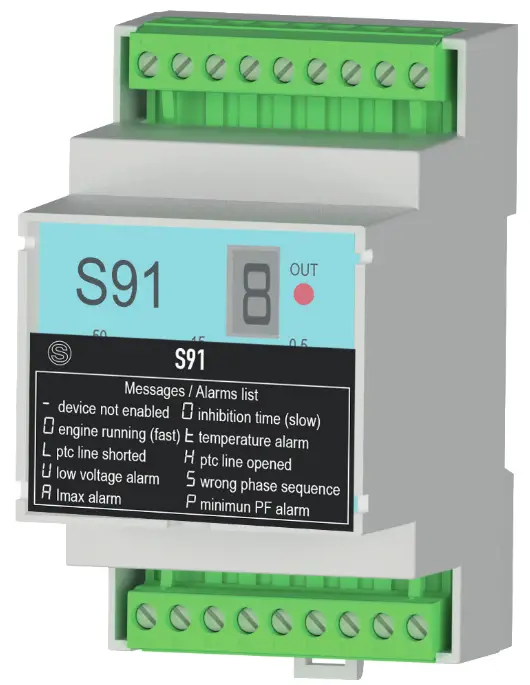
MODULE LAYOUT
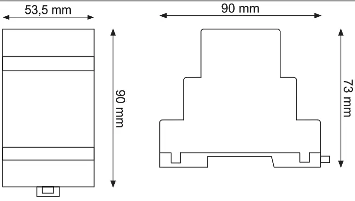
Dimensions LxHxD 53.5 x 73 x 90 mm; Weight: 250 g; Enclosure: UL94 VO, colour ral 7035
SIGNALS VIA LED ON FRONT PANEL
| LED | STATUS | LED meaning |
| OUT (Red) | On | Energized relay |
| Off | De-energized relay |
FRONT DISPLAY
| Display | Meaning | Display | Meaning |
| Device disabled |
| Phase failure or minimum voltage alarm |
| Inhibition time (slow rotation) |
| Phase sequence alarm |
| Motor rotating (fast rotation) |
| Overcurrent alarm |
| PTC sensor line short-circuited |
| Minimum P.F. alarm |
| PTC sensor line interrupted | T | Temperature alarm |
PRELIMINARY WARNINGS
The word WARNING preceded by the symbol ![]() indicates conditions or actions that put the user’s safety at risk.
indicates conditions or actions that put the user’s safety at risk.
The word ATTENTION preceded by the symbol![]() indicates conditions or actions that might damage the instrument or the connected equipment.
indicates conditions or actions that might damage the instrument or the connected equipment.
The warranty shall become null and void in the event of improper use or tampering with the module or devices supplied by the manufacturer as necessary for its correct operation, and if the instructions contained in this manual are not followed.
| WARNING: The full content of this manual must be read before any operation. The module must only be used by qualified electricians. Specific documentation is available at www.seneca.it/products/s91 | |
 | The module must be repaired and damaged parts replaced by the Manufacturer. The product is sensitive to electrostatic discharges. Take appropriate measures during any operation. |
 | Electrical and electronic waste disposal (applicable in the European Union and other countries with recycling). The symbol on the product or its packaging shows the product must be surrendered to a collection center authorized to recycle electrical and electronic waste. |
TECHNICAL SPECIFICATIONS
| STANDARDS | EN61000-6-4 Electromagnetic emissions, industrial environment. EN6100062 Electromagnetic immunity, industrial environment. EN61010-1 Safety |
| INSULATION | 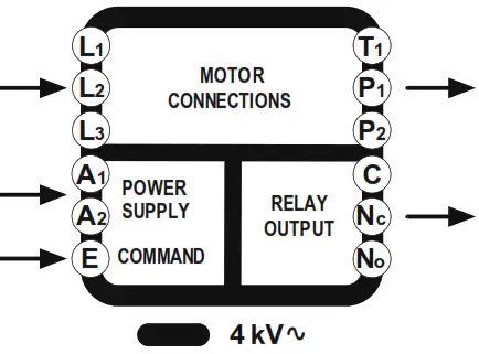 Withstand voltage: 2.5 kV Withstand voltage: 2.5 kVImpulse withstand voltage: 4 kV Rated insulation voltage: 300 V (Cat III) 600 V (Cat II) Pollution rating 2 |
| BNRONIENTAL CONDITIONS | Temperature: -20 – + 65°C Humidity: 30%- 90% non condensing. Storage temperature: -20 + 85° Protection rating: IP20 |
| ASSEMBLY | IEC EN60715, 35mm DIN rail in vertical position. |
| CONNECTIONS | Screw terminals, 7.5 mm pitch, cable with <2.5 mm2secbon, 0.5 Nm tightening torque |
| POWER SUPPLY | Rated voltage: 195 + 255 Vac (591)1400 Vac ± 10 % (591-400) Rated frequency: 50-60Hz±5% Maximum absorbed power: 1.5 W |
| CURRENT MEASUREMENT | Type of insertion: Direct or through an Ammeter Transformer Rated operational current (le): 16 Mc Current measurement limits: 0.1 + 16 Aac. measurement precision < 5% Input type: Shunt Type of measurement: TRMS Continuous thermal limit: 16 Mc Impulsive thermal limit: 45 Mc for 1 sec Dynamic limit: 200 Mc for 10 msec Self-consumption: 1.3 W Phase failure intervention: < 200 msec |
| VOLTAGE MEASUREMENT | Rated LIE voltage 347 (L-N)1600 (L-L) Vac Cat II; 277 (L-N) 1480 (L-L) Vac Cat III Voltage measurement limits: 60 + 660 Vac, measurement precision < 5% Frequency limits: 50 – 60 Hz ± 5% Connection methods: L1-L2-L3 or L-N No voltage intervention Threshold: 80 Vac (single- and three-phase) ony I:Oren:base:IN difference tehmen max. phaseNAME phase calmed b the male phase is > 20% |
| MOTOR CONTROL INPUT | Rated voltage: 195 + 255 Vac (S91) / 400 Vac ± 10 % (S91-400) Operating limits: 0.85 + 1.1 of rated voltage Absorbed/dissipated power: 0.17 W Minimum command duration: am ms |
| RELAY OUTPUT | Type of output 1 exchange Working voltage: 400 Vac Working current: 8 A |
| PTC MEASUREMENT | Input not isolated from the mains, maximum cable length 30 m Precision: range 1650 + 3100 CI, error < 5% Short circuit detection: <300 ± 50 Open circuit detection: > 141E3 ±0.2 KO |
GENERAL DESCRIPTION
Protection devises for electric motors capable of detecting the wrong sequence of phases, the lack of a phase, the excess of absorbed current, and the no-load operation with the measurement of the power factor.
It is also equipped with a PTC input for the protection of the motor from over-temperature and an enabling input to start the motor.
The main use is the protection of single-phase or three-phase pumps, protecting them against dry running, possible rotor blockage, and over-temperature (if equipped with PTC).
It is also suitable for detecting the breakage of mechanical transmission devices, for example, belts or chains, and to protect against transmission system blocks.
The following operating modes can be set using the panel selector:
- single-phase or three-phase measurement
- maximum current range 5 or 16 A
- operation with or without PTC
FRONT SELECTOR CONFIGURATION
| SELECTOR | PARAMETER | DESCRIPTION | ||
| MODE | Type of operation | | ||
| Mode | Selected function | Mode | Selected function | |
| 1 | Single-phase 5A without temperature control | 5 | Single-phase 16A without temperature control | |
| 2 | Single-phase 5A with PTC motor control | 6 | Single-phase 16A with PTC motor control | |
| 3 | Three-phase 5A without temperature control | 7 | Three-phase 16A without temperature control | |
| 4 | Three-phase 5A with PTC motor control | 8 | Three-phase 16A with PTC motor control | |
FRONT TRIMMER ADJUSTMENT
| TRIMMER | PARAMETER | RANGE | DESCRIPTION |
| AR | Auto-reset time | 0 = disabled 1 ÷ 100 min | Setting the Auto Restart time in minutes. If automatic restart is not desired, set to 0. |
| TD | Inhibition time | 1 ÷ 30 sec | Setting the inhibition time in seconds. Disables the IMAX% (overcurrent) and PF (power factor lower than the minimum) alarms during engine start. |
| PF | Minimum power factor | 0 ÷ 1 | Threshold value below which the minimum Power Factor alarm is generated. (low load operation). |
| OT | Intervention time | 0.2 ÷ 10 sec | Setting the attack time in seconds indicates how long the IMAX% measurement can exceed the set threshold or how long the P.F. can drop below the minimum set value. |
| IMAX% | Maximum current: | 0% ÷ 100% of full scale | Setting in percentage. The threshold value that, when exceeded, triggers the overcurrent alarm. |
ENABLE INPUT
The device is equipped with an enable input that allows you to activate/deactivate the motor.
During the first start-up or if there are no alarms, the absence of the enable signal causes the “-” symbol to appear on the display and the motor control relay to de-energize.
In normal conditions, when enabled, a segment is turned on on the display which rotates along with the “0” and the command relay is energized to activate the motor.
On power-up, the rotation speed with which the segment lights up is low: this indicates that the motor is starting up for the set DT inhibition time (IMax and PFmin are not measured).
In the following phase, the segment rotates at a higher speed: this indicates that the motor is operating normally and that the alarm control is again active.
If the enable signal is removed after the appearance of any alarm, the latter signal remains fixed on the display. When the enable signal returns, the alarm is canceled and the control relay is energized to restart the motor.
ALARM DISPLAY
Alarm messages are shown on the display in two different ways with the following meaning:
- – Alarm with flashing display: indicates that the device will attempt to restore operation at the end of the AR auto reset time.
This mode is active only if the AR auto-reset time is greater than zero. - – Alarm with fixed display: Auto-reset disabled, no automatic restart or reset. An external action by an operator is required to restart.
Possible actions: Turn the device off and on again or deactivate and reactivate the enabling input.
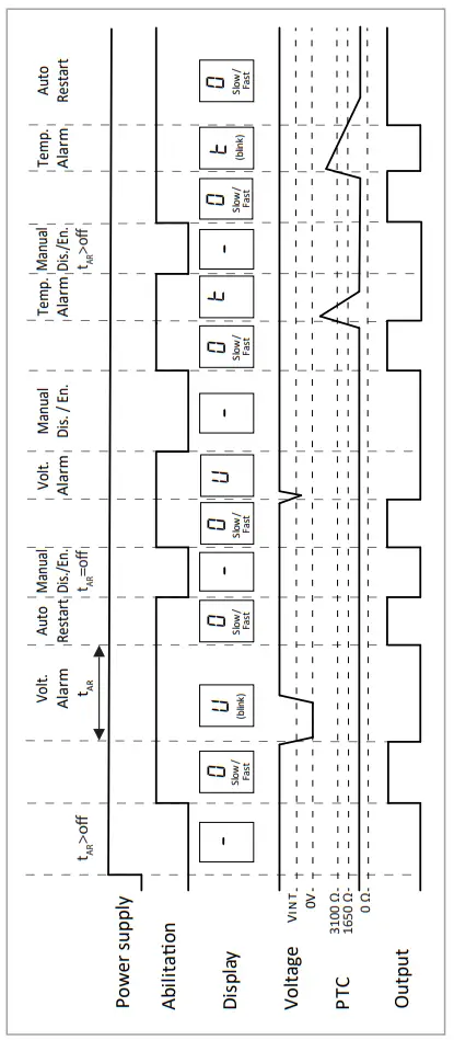
TEMPERATURE ALARM THROUGH PTC
This function involves the use of a thermistor housed near the windings of the motor connected to terminals P1 and P2 of the device.
The intervention temperature depends on the type of PTC installed in the motor;
The over-temperature alarm is signaled with the symbol t on the display, moreover, the device also checks for the presence of a short circuit on terminals P1 and P2 (Alarm L on the display) or the interruption of the connection with the sensor (Alarm H on the display ). This alarm is automatically reset if the temperature drops below the set threshold if the AR auto reset time is greater than zero.![]() WARNING: The PTC input is not isolated from the line that powers the motor: use the necessary precautions to prevent an electric shock. If you do not want to use this protection, you must set the MODE selector appropriately before turning on the device.
WARNING: The PTC input is not isolated from the line that powers the motor: use the necessary precautions to prevent an electric shock. If you do not want to use this protection, you must set the MODE selector appropriately before turning on the device.
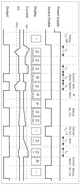
MAXIMUM CURRENT ALARM
This function involves selecting a current scale between 5A and 16A using the MODE selector before switching on the device. The over-current alarm is signaled with the symbol A on the display when the current absorbed by the motor exceeds the percentage threshold set on the device. This alarm is automatically reset when the current drops below the set threshold if the AR auto reset time is greater than zero.
During the auto-reset time, the symbol A flashes and at the end the motor restarts.
N.B.: During normal operation, when the set IMax threshold is exceeded, the symbol A alternates with the symbol O during the set OT trip time.
POWER FACTOR ALARM
This function has a threshold adjustable between 0 and 1. The power factor alarm is signaled with the symbol P on the display when the Power Factor drops below the minimum threshold set on the device. This alarm is automatically reset when the Power Factor returns or exceeds the set threshold if the AR auto reset time is greater than zero. During the auto-reset time the P symbol flashes and at the end the motor starts.
N.B.: During normal operation, when the set PFmin threshold is exceeded, the symbol A alternates with the symbol O during the set OT trip time.
MINIMUM VOLTAGE OR PHASE FAILURE ALARM
This function involves selecting the type of operation between three-phase and single-phase using the MODE selector before turning on the device. The alarm highlighting that the voltage is below the minimum threshold or a phase is failing is shown by the U symbol on the display. The thresholds of this alarm are internally preset and cannot be changed by the user. The intervention of this alarm is immediate (detection time <200ms) and can be automatically reset if the AR auto reset time is greater than zero. In this case, the U symbol flashes on the display for the entire set auto reset time and then the device tries to restart the motor.
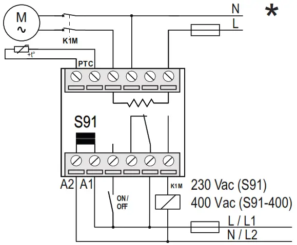
ELECTRICAL CONNECTIONS
TERMINAL BLOCK LAYOUT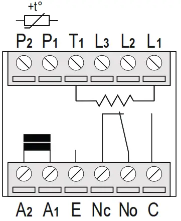
NB: it is always necessary to install a suitable protection upstream
TERMINAL DESCRIPTION
P1 = Motor protection input (PTC) *
P2 = Motor protection input (PTC) *
T1 = L1 output
L1 = Line 1 input
L2 = Line 2 input
L3 = Line 3 input
A2 = Auxiliary power 230 Vac / 400 Vac
A1 = Auxiliary power 230 Vac / 400 Vac
E= Motor control input
Nc = Normally closed contact relay
C = Contact common relay
No = Normally open contact relay
(*) ![]() WARNING: input not isolated from the mains
WARNING: input not isolated from the mains
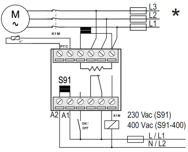
THREE-PHASE MOTOR WITH
DIRECT CURRENT MEASUREMENT
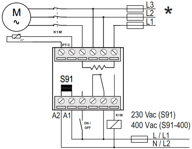
 THREE-PHASE MOTOR WITH CURRENT
MEASUREMENT WITH AMMETER TRANSFORMER
SINGLE-PHASE MOTOR WITH
DIRECT CURRENT MEASUREMENT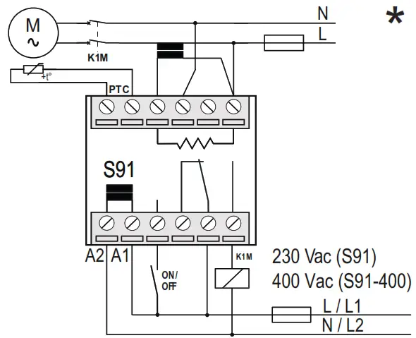
* A thermal-magnetic switch must be inserted near the device
SINGLE-PHASE MOTOR WITH CURRENT
MEASUREMENT WITH AMMETER TRANSFORMER
PTC AND VOLTAGE OPERATING DIAGRAM
CURRENT AND PF (POWER FACTOR) OPERATING DIAGRAM
CONTACT INFORMATION
| Technical support | [email protected] | Product information | [email protected] |
This document is the property of SENECA srl. Copies and reproduction are prohibited unless authorized.
The content of this document corresponds to the described products and technologies.
Stated data may be modified or supplemented for technical and/or sales purposes.
Fax +39.049.8706287


