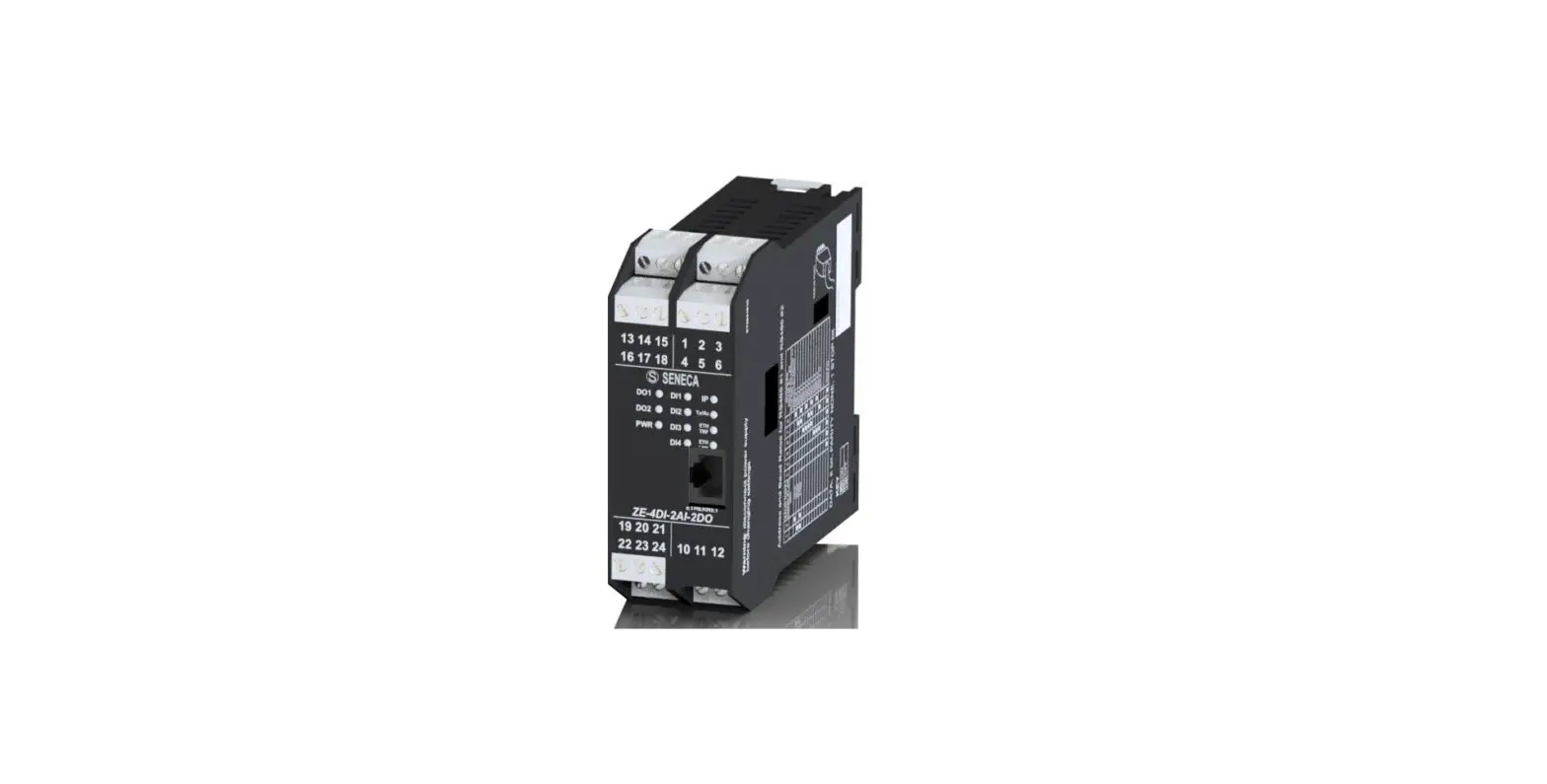
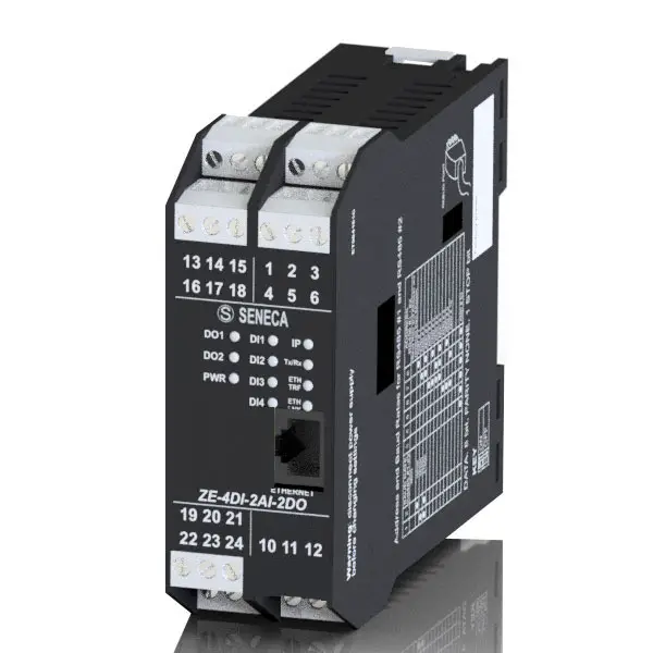
SENECA Z-PASS2-R IoT Multifunction Controllers
DIMENSION
MODULE LAYOUT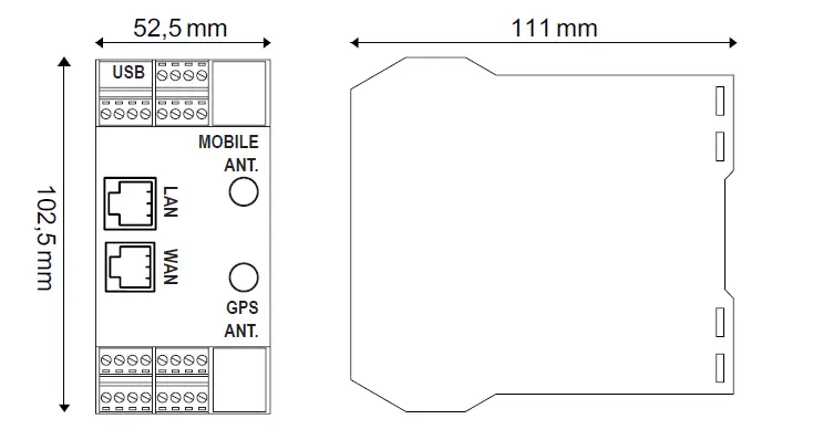
SIGNALS VIA LED ON FRONT PANEL
| LED | STATUS | LED meaning | |
| PWR | On | Device powered correctly | |
| Off | Device not powered | ||
| RUN | On | Locking system | |
| Flashing | The module is working correctly | ||
| Off | System Locked / Booting | ||
| DIDO1.. DIDO6 | On | Input or output activated | |
| Off | Input or output deactivated | ||
| VPN | On | VPN connection active | |
| Flashing | VPN connection problems | ||
| SRV | On | VPN BOX “SERVICE” connection is working correctly | |
| Flashing | VPN BOX “SERVICE” connection in error | ||
| Off | VPN BOX “SERVICE” connection disabled | ||
| RX1 / RX2 / RX4 | On | Incorrect RS485/ RS232 connection | |
| Flashing | Reception of data packet completed on RS485/ RS232 | ||
| TX1 / TX2 / TX4 | Flashing | Transmission of data packet completed on RS485/ RS232 | |
| ETH ACT (Green) | Flashing | Packet transit on Ethernet port | |
| ETH LNK (Yellow) | On | Ethernet port connected | |
 | On | Signal level reporting | |
| Flashing (Only | Modem not correctly adjusted | ||
| NET | On | Modem adjusted on 4G network | |
| Flashing | Modem adjusted on 2G or 3G network | ||
| Off | Modem off or not adjusted | ||
| DATA | On | Data connection enabled and correctly adjusted | |
| Flashing | Data connection enabled but in error | ||
| Off | Data connection disabled | ||
| GPS | On | GPS signal present | |
| Off | GPS signal absent | ||
| BAT See user manual | On | Battery connected and working properly | |
| Flashing | Low or faulty battery | ||
| Off | Battery not in use (UPS not active) | ||
| PWR (MODEM) | On | Device powered correctly | |
| Off | Device not powered | ||
TECHNICAL SPECIFICATIONS
| CERTIFICATIONS | ||
| POWER SUPPLY | 11 ÷ 40Vdc; 50 ÷ 60Hz; Max absorption: 6 W | |
| ENVIRONMENTAL CONDITIONS | Operating temperature: from -25°C to +65°C; Humidity: 10% ÷ 90% non condensing. Storage temperature: from -30°C to +80°C; Degree of protection: IP20 | |
| ASSEMBLY | 35mm DIN rail IEC EN60715 | |
| CONNECTIONS | Removable 3.5 mm pitch terminal block, 1.5 mm2 max cable section | |
| PROCESSOR | ARM 32 bit | |
| MEMORY | 512MB RAM and ≥ 4GB Flash; PUSH-PUSH type slot for micro SD | |
| FEATURES | Integrated Web Server and update via Web Server | |
| COMMUNICATION PORTS | COM1: RS232 / RS485 (on terminals), COM2: RS485 (on terminals or IDC10) COM4: RS485 (on terminals); maximum Baud rate 115kbps; minimum 200 bps; USB HOST type A ETH1 and ETH2 Fast Ethernet RJ45 10/100Mbps, Maximum connection distance: 100 m CAN (on terminals). | |
| ISOLATION | 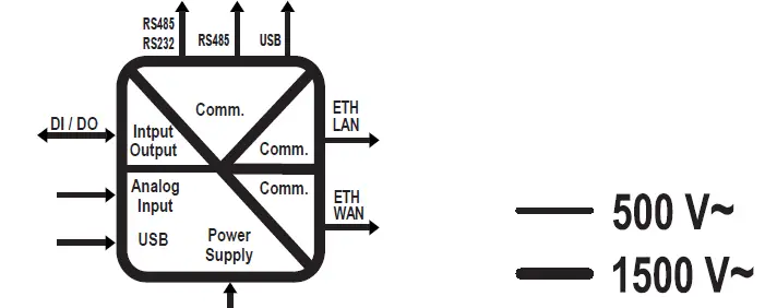 | |
| DIGITAL INPUTS OUTPUTS | Number of inputs: 6 max.; Number of outputs: 6 max.; Absorbed current: 3mA @ 12Vdc, 5mA @ 24Vdc. Voltage OFF<4V, ON>8V MAX. current (Vout+) 50mA Voltage (Vext+): 10 ÷ 28Vdc. MAX. current: 200 mA per channel Protect the outputs using a 1.5A fuse as shown in the wiring diagrams | |
| ANALOGUE INPUTS | Voltage 0 ÷ 30Vdc, impedance 200kΩ Current 0 ÷ 25mA, impedance ~ 50Ω | |
| AUXILIARY VOLTAGE OUTPUT | V AUX: 12Vdc; Max. 50 mA | |
| 4G MODEM FREQUENCIES | Global coverage Model 4G/LTE LTE-FDD: B1/B2/B3/B4/B5/B7/B8/B12/B13/B18/ B19/B20/B25/B26/B28 LTE-TDD: B38/B39/B40/ B41; WCDMA: B1/B2/B4/B5/B6/B8/B19/GSM: B2/B3/B5/B | |
| OUTPUT POWER | GSM900: 32.75dBm, DCS1800: 29.07dBm, WCDMA: 23.13dBm, 23.27 dBm, LTE: 23.1dBm, 23.2dBm, 21.7dBm, 23.19dBm, 23.14dBm, 23.7dBm, 23.39dBm. | |
| GNSS | GPS / GLONASS / BeiDou (compass) / Galileo / QZSS | |
| SIM CARD SLOT | Push-push type for mini SIM card 15 X 25 mm | |
INSTALLATION REGULATIONS
The module has been designed for vertical installation on a DIN 46277 rail. For optimal operation and long life, adequate ventilation must be provided. Avoid positioning ducting or other objects that obstruct the ventilation slots. Avoid mounting modules over heat-generating equipment. Installation in the bottom part of the electrical panel is recommended.
ATTENTION: These are open type devices intended for installation in a final casing/panel that offers mechanical protection and protection against the spread of fire.
ModBUS CONNECTION RULES
- Install the modules in the DIN rail (120 max)
- Connect the remote modules using cables of an appropriate length. The following table shows cable length data:
- Bus length: maximum length of the Modbus network according to the Baud Rate. This is the length of the cables that connect the two farthest modules.
- Derivation length: maximum length of a derivation 2 m.
- For maximum performance, it is recommended to use special shielded cables, designed specifically for data communication.
WARNING: This is a Class A product. In a residential environment this equipment may cause radio interference. In this case, the user may have to take adequate countermeasures.
IDC10 CONNECTOR
Power supply and Modbus interface are available also using the Seneca DIN rail bus, via the IDC10 rear connector, or the Z-PC-DINAL2-17.5 accessory.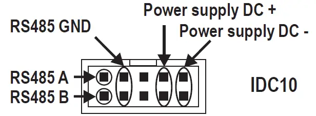
Back connector (IDC 10)
The illustration shows the meanings of the various IDC10 connector pins if signals are to be sent via them directly.
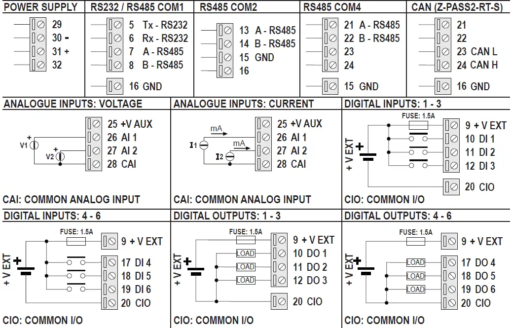
ELECTRICAL CONNECTIONS
CAUTION: Switch the module off before connecting inputs and outputs.
To meet the electromagnetic immunity requirements:
- use shielded signal cables;
- connect the shield to a preferential instrumentation earth system;
- separate shielded cables from other cables used for power installations (transformers, inverters, motors, etc…).

SETTING THE DIP-SWITCHES
WARNING: The DIP-switch settings are read only at boot time. At each change, perform a restart. For use and settings via DIP-SWITCH SW1 see the user manual available on the website on the web page dedicated to the product.
PRELIMINARY WARNINGS
The word WARNING preceded by the symbol indicates conditions or actions that put the user’s safety at risk. The word ATTENTION preceded by the symbol indicates conditions or actions that might damage the instrument or the connected equipment. The warranty shall become null and void in the event of improper use or tampering with the module or devices supplied by the manufacturer as necessary for its correct operation, and if the instructions contained in this manual are not followed.
WARNING: The full content of this manual must be read before any operation. The module must only be used by qualified electricians. Specific documentation is available using the QR-CODE shown on page 1. The module must be repaired and damaged parts replaced by the Manufacturer. The product is sensitive to electrostatic discharges. Take appropriate measures during any operation. Electrical and electronic waste disposal (applicable in the European Union and other countries with recycling).The symbol on the product or its packaging shows the product must be surrendered to a collection centre authorized to recycle electrical and electronic waste 
- SENECA s.r.l.;
- Via Austria, 26 – 35127
- PADOVA – ITALY;
- Tel. +39.049.8705359
- Fax +39.049.8706287
CONTACT INFORMATION
| Technical support | [email protected] | Product information | [email protected] |
This document is the property of SENECA srl. Copies and reproduction are prohibited unless authorized. The content of this document corresponds to the described products and technologies. Stated data may be modified or supplemented for technical and/or sales purposes.


