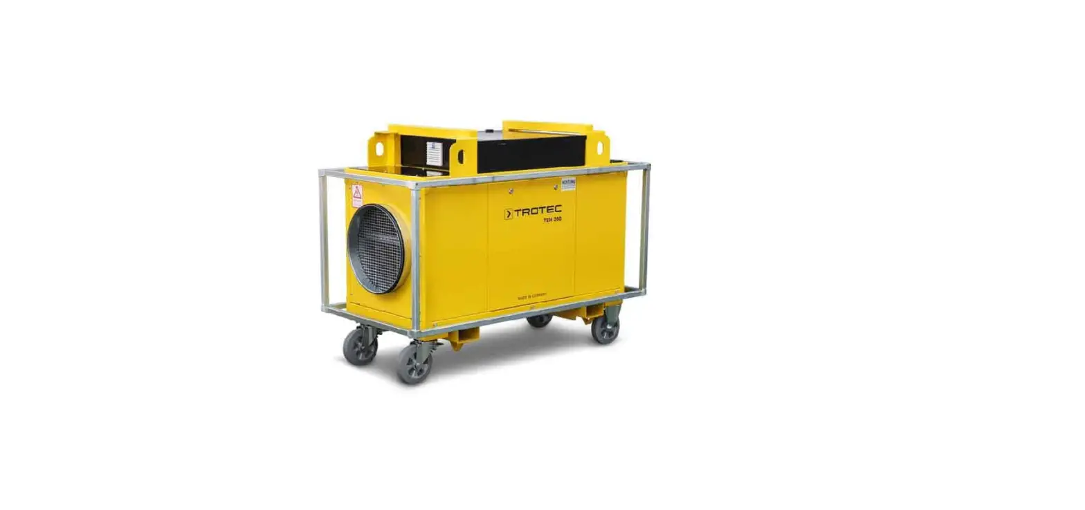
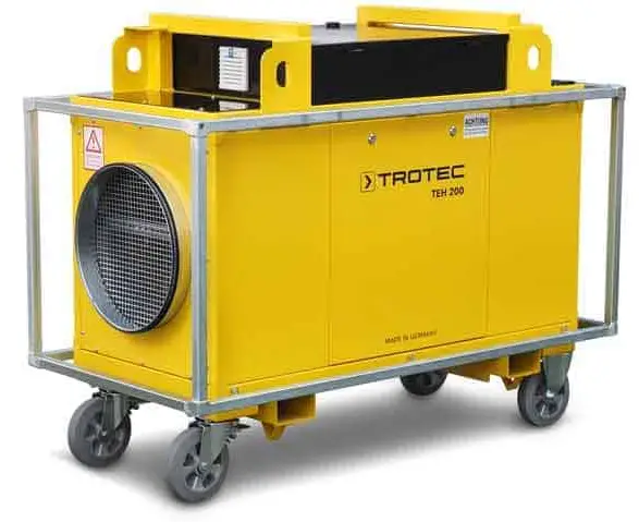
TROTEC TEH 300 Electric Heater
Notes regarding the instructions
Symbols
Warning of electrical voltage
- This symbol indicates dangers to the life and health of persons due to electrical voltage.
Warning of hot surface
- This symbol indicates dangers to the life and health of persons due to hot surface.
Warning: This signal word indicates a hazard with an average risk level which, if not avoided, can result in serious injury or death.
Caution: This signal word indicates a hazard with a low risk level which, if not avoided, can result in minor or moderate injury.
Note: This signal word indicates important information (e.g. material damage), but does not indicate hazards.
Info
- Information marked with this symbol helps you to carry out your tasks quickly and safely.
Follow the manual
- Information marked with this symbol indicates that the instructions must be observed.
You can download the current version of the instructions via the following link
TEH 200
TEH 300

TEH 400

Safety
Read this manual carefully before starting or using the device. Always store the manual in the immediate vicinity of the device or its site of use.
Warning
Read all safety warnings and all instructions. Failure to follow the warnings and instructions may result in electric shock, fire and / or serious injury. Save all warnings and instructions for future reference.
- Do not use the device in potentially explosive rooms and do not install it there.
- Do not use the device in aggressive atmosphere.
- Do not use the device in atmospheres containing oil, sulphur, chlorine or salt.
- This appliance is not a toy. Keep away from children and animals. Do not leave the device unattended during operation.
- Only put up the device in an upright, stable position on firm ground.
- Make sure that the air inlet and outlet are not obstructed.
- Make sure that the suction side is kept free of dirt and loose objects.
- Do not place the device on combustible ground.
- Never insert any objects or limbs into the device.
- Do not cover the device during operation.
- Do not use the device with wet or damp hands.
- Let the device dry out after a wet clean. Do not operate it when wet.
- Do not expose the device to directly squirting water.
- Check accessories and connection parts for possible damage prior to every use of the device. Do not use any defective devices or device parts.
- Ensure that all electric cables outside of the device are protected from damage (e.g. caused by animals). Never use the device if electric cables or the power connection are damaged!
- The mains connection must correspond to the specifications in the Technical annex.
- Insert the mains plug into a properly fused mains socket.
- Disconnect the device from the mains, if it is not in use.
- Do not remove any safety signs, stickers or labels from the device. Keep all safety signs, stickers and labels in legible condition.
- Do not sit on the device.
- When positioning the device, observe the minimum distances from walls and other objects as well as the storage and operating conditions specified in the Technical annex.
- Before carrying out maintenance, care or repair work on the device, remove the mains plug from the mains socket. Hold onto the mains plug while doing so.
- Switch the device off and disconnect the power cable from the mains socket when the device is not in use.
- Do not under any circumstances use the device if you detect damages on the mains plug or power cable. If the power cable is damaged, it must be replaced by the manufacturer, its service agent or similarly qualified persons in order to avoid a hazard. Defective power cables pose a serious health risk!
- Only use original spare parts, for otherwise safe and functional operation cannot be ensured.
- Allow the device to cool down before transport and/or maintenance work.
- Do not use this device near bathtubs, shower trays, swimming pools or other water containers. Risk of electric shock!
Intended use
- Only use the device TEH 200 / TEH 300 / TEH 400 for heating atmospheric air (intake temperature: -20 °C to max. +40 °C) whilst adhering to the technical data.
Foreseeable misuse
- The device TEH 200 / TEH 300 / TEH 400 is not suited for installation in fluids or on flooded or boggy grounds. The device must not be used for sucking in fluids, e.g. from filled tanks or basins.
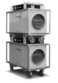
- The devices must not be operated when stacked on top of one another for storage.
- Any unauthorised changes, modifications or alterations to the device are forbidden.
Personnel qualifications
People who use this device must:
- be aware of the dangers that occur when working with electric heaters.
- have read and understood the instructions, especially the Safety chapter.
Maintenance tasks which require the housing to be opened must only be carried out by specialist electrical companies or by Trotec.
Electrically skilled person
Electrically skilled personnel must be able to read and understand electric circuit diagrams, to put electrical systems into service and to maintain them, to wire control cabinets, to ensure the functionality of electrical components and to identify possible hazards from electrical and electronic systems.
Instructed person
Instructed persons have been informed of the tasks they were entrusted with as well as of potential hazards resulting from inappropriate behaviour. They are allowed to operate and transport the device and perform simple maintenance activities (cleaning the housing, cleaning the fan). The device is to be maintained and looked after by instructed personnel.
Residual risks
Warning of electrical voltage
- Work on the electrical components must only be carried out by an authorized specialist company!
Warning of electrical voltage
- Before any work on the device, remove the mains plug from the mains socket!
- Do not touch the mains plug with wet or damp hands.
- Hold onto the mains plug while pulling the power cable out of the mains socket.
Warning of hot surface
- Parts of this appliance can become very hot and cause burns. Particular attention is to be paid when there are children or vulnerable persons present!
Warning
- Improper handling entails a risk of burning and electric shock.
- Only use the device as intended!
- Dangers can occur at the device when it is used by untrained people in an unprofessional or improper way! Observe the personnel qualifications!
- The device is not a toy and does not belong in the hands of children.
- Risk of suffocation!
- Do not leave the packaging lying around. Children may use it as a dangerous toy.
- The air outlet grille becomes very hot during operation and cause burns if touched! To not touch it. Keep a distance.
- To avoid damages to the device, never operate the device without an inserted air filter!
- Improper installation entails a risk of fire.
- Do not place the device on combustible ground.
- Do not place the device on high-pile carpets.
- In order to avoid overheating and fire hazards, the device must not be covered!
Behaviour in the event of an emergency
- Immediately switch the device off via the main emergency stop switch or the emergency stop at the upstream distributor.
- Remove persons from the danger area.
- Disconnect the device from the electric circuit.
- Do not reconnect a defective device to the mains.
Information about the device
Device description
The electric heater was designed as a robust, mobile unit also to be positioned outdoors. The device comes equipped with two lockable swivel castors (5) and two trestle rollers (7) each. Forklift pockets and crane lugs are attached to the housing as transport aids, enabling convenient transport and space-saving storage by stacking up to 3 devices on top of each other.
The housing is designed as welded frame construction and provided with partially removable steel sheet panels. The electrical control box made of steel is mounted in horizontal position, protected between the stacking handle bars on the housing, and contains all switching devices, operating elements, indicator lights, safety devices and the control unit. All steel and sheet metal parts are galvanized and powder-coated. The device is designed ready-to-install and comes with all the electrical and mechanical components as well as safety installations required for safe and functional operation. To ensure safe transport and operation, the device is also equipped with a shock protection frame.
Functioning principle
The air is taken in by the fan via the integrated bag filter (10) and heated by means of multi-stage electric heating. Four different temperature levels can be selected between 0 and 100 %. These are kept constant by the integrated controller with the maximum outlet temperature being reduced to approx. 60 °C (±5 °C).
Thanks to the two-stage fan operation a higher temperature increase can be achieved by selecting the lower stage (approx. 2/3 of the nominal air volume). The integrated, electronically controlled control unit with air volume flow measurement and automatic rotational speed control of the fan ensures nearly constant volumetric flow rates covering a wide load range (e.g. for variable hose lengths). The temperature increase refers to the sucked in air temperature (usually the ambient temperature) and is increased according to the preselection. The temperature sensors at air inlet and outlet transmit the current temperature values to the control unit, which then, depending on the demand, keeps the preselected temperature increase constant by means of the control and operation of individual heating elements or the entire heater.
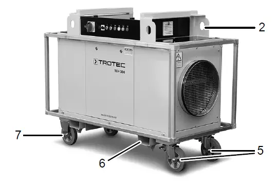
Device depiction
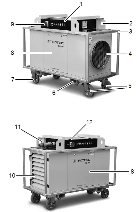
| No. | Designation |
| 1 | Control panel with electrical control box |
| 2 | Transport lug |
| 3 | Shock protection frame |
| 4 | Air outlet with hose connection |
| 5 | Swivel castor (lockable) |
| 6 | Forklift pockets |
| 7 | Trestle rollers / fixed castors |
| 8 | Lateral cover panel |
| 9 | Main switch with emergency stop function |
| 10 | Air inlet with weather protection grid and air filter access |
| 11 | Mains connection: CEE plug, 5-pin |
| 12 | Cover flap electrical control box |
Transport and storage
Note
- If you store or transport the device improperly, the device may be damaged.
- Note the information regarding transport and storage of the device.
Transport
- Remove all packing materials which serve to protect the device during transport.
- Should the electric heater be damaged, please contact the responsible dealer or manufacturer, where the purchase was made.
- The electric heater may only be lifted at the points provided with lifting gear (forklift pockets (6), transport lugs (2)) intended for handling. The carrying capacity of the lifting gear must be suitable for the weight of the electric heater (see technical data).
To make the device easier to transport, it is fitted with wheels. Only wheel the device on firm, level ground. The following should be observed before transporting the device using the castors:
Warning
- Trip hazard! Make sure that nobody is situated in the immediate proximity.
- The following should be observed before transporting the device using lifting gear:
Warning: Risk of injury from suspended loads. Make sure that nobody is situated in the immediate proximity.
- Only instructed persons are allowed to perform the transport by use of lifting gear.
- Consider the centre of gravity when transporting the load. The following should be observed after transporting the device:
- Lock the swivel castors (5)!
Storage
When the device is not being used, observe the following storage conditions:
- Store the device in a dry location and protected from frost and heat.
- Store the device in an upright position where it is protected from dust and direct sunlight.
- If required, use a cover to protect the device from invasive dust.
- Before restarting the device, check the condition of the power cable. If there are doubts as to the sound condition, contact the customer service.
- Have the device checked once a year by an electrically skilled person at any rate.
The device can be stacked for storage purposes. In doing so, observe the following
- Only use suitable lifting gear.
- Make sure that the rollers of the device at the bottom are locked and the device cannot move. To protect the rollers and the frame, the bottommost device is to be jacked up as illustrated below.
Warning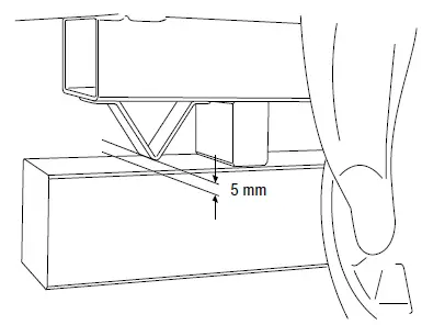
- To prevent damage to the device, the bottom strut should not be allowed to rest on the support. A minimum distance of 5 mm to the bottom must be observed!

- Make sure that the wheels of the device to be stacked are pointing inwards as indicated in the figure below.
- The maximum amount of devices to be stacked on top of one another is 3 (for transportation in a truck: max. 2 devices).
- Place the device at the bottom on firm, level ground.
Assembly and installation
Scope of delivery
- 1 x Device
- 1 x Manual
Start-up
Warning
Operating several devices stacked onto one another is prohibited for safety reasons. Do not take the devices into operation when stacked. When positioning the device, observe the minimum distance from walls or other objects as described in the chapter Technical annex.
- Before restarting the device, check the condition of the power cable. If there are doubts as to the sound condition, contact the customer service.
- Position the device on firm, dry and level ground.
- Depending on the floor load capacity a panel for weight distribution is to be provided.
- When setting up the device, ensure a sufficient distance for air inlet and outlet as well as for operation (see Technical data).
- Lock the swivel castors and secure the device against rolling away.
- Do not create tripping hazards when laying the power cable or other electric cables, especially when positioning the device in the middle of the room. Use cable bridges.
- Make sure that extension cables are completely unrolled.
- When positioning the device outdoors, make sure that no water can enter the device through the air outlet. Connect an air hose to the air outlet to minimize the risk.
- Make sure that no curtains or other objects interfere with the air flow.
- Make sure that the device cannot come into contact with moisture or water.
Inserting the air filter
Note
- Do not operate the device without an air filter inserted into the air inlet!
- Without the air filter, the inside of the device will be heavily contaminated. This could reduce the performance and result in damage to the device.
- Make sure that the air filter is installed before switching the device on.
Connecting the power cable
- Insert the mains plug into a properly fused mains socket.
Operation
Control panel
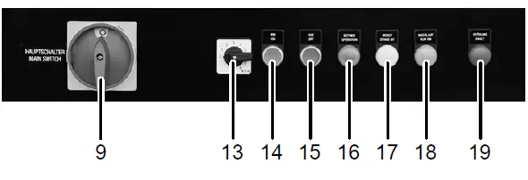
| No. | Designation | Meaning |
| 9 | Emergency stop main switch | Main switch with emergency stop function Position 0: The device is switched off (emergency stop). Position I: The device is switched on. |
| 13 | Selection step switch | For setting the desired temperature level |
| 14 | Button EIN-ON | Switches the device on. |
| 15 | Button AUS-OFF | Switches the device off and initiates the rundown function. |
| 16 | Lamp BETRIEB- OPERATION | Illuminated during operation. |
| 17 | Lamp BEREIT- STAND BY | Illuminated when in standby mode. |
| 18 | Lamp NACHLAUF- RUN ON | Illuminated during the rundown function. |
| 19 | Lamp STÖRUNG- FAULT | Illuminated in case of a fault. |
Note
The emergency stop main switch (9) serves for switchon and may only be used as emergency stop switch for the disconnection from the mains in case of an emergency. For normal switch-off please use the AUS-OFF button (15), which initiates the rundown function (NACHLAUF-RUN ON lamp (18) illuminated). Only disconnect the device for transport or storage via the main switch at the end of the rundown period.
Switch-on of the device
- The side covers, the electrical control box and the weather protection grid are closed.
- The bag filter is built in correctly.
- Air inlet and air outlet are free from objects and/or obstructions.
- The device is secured against rolling away.
- Insert the mains plug into a properly secured mains power socket. Observe the rotating field (clockwise rotation).
- Rotate the mains switch (9) to position “I”.
- The control unit is activated.
- The device is ready for operation.
- The BEREIT-STAND BY lamp (17) lights up.
- Select the desired temperature level via the selection step switch (13).
Note: Selecting the temperature level does not limit the electric current consumption from the mains!
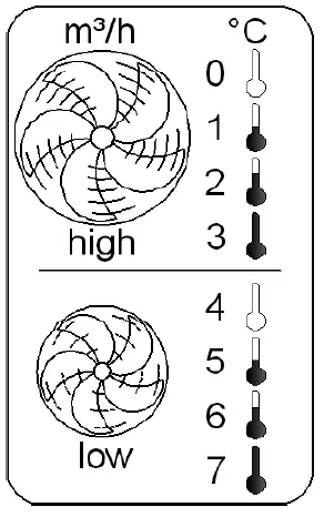
| No. | Meaning |
| 0 | 100 % air flow rate and no temperature increase |
| 1 | 100 % air flow rate and low temperature increase (∆ T = approx. 15 °C) |
| 2 | 100 % air flow rate and moderate temperature increase (∆ T = approx. 25 °C) |
| 3 | 100 % air flow rate and maximum temperature increase (∆ T = approx. 40 °C) |
| 4 | 66 % air flow rate and no temperature increase |
| 5 | 66 % air flow rate and low temperature increase (∆ T = approx. 20 °C) |
| 6 | 66 % air flow rate and moderate temperature increase (∆ T = approx. 40 °C) |
| 7 | 66 % air flow rate and maximum temperature increase (∆ T = approx. 60 °C) |
- Actuate the green EIN-ON button (14).
- The green BETRIEB-OPERATION lamp (16) will be illuminated while the BEREIT-STAND BY lamp (17) goes out.
- The electric heater starts up in the selected temperature level.
Note: The air outlet temperature is electronically limited to approx. 60 °C (±5 °C) regardless of the preselection. In case of the standard models the levels 0 to 7 are engaged. In case of devices without air volume switching only the levels 0 to 3 are engaged. The levels 8 and upwards are reserved for special designs.
Switch-off
- Press the red AUS-OFF button (15).
- The heating switches off.
- The fan operates in rundown mode, e.g. the fan runs on until the heating elements have cooled down to below 40 °C.
- The BETRIEB-OPERATION lamp (16) goes out.
- The NACHLAUF-RUN ON lamp (18) is illuminated.
- The BEREIT-STAND BY lamp (17) is illuminated.
- Restart can be carried out at any time.
- Wait until rundown operation is completed.
- The NACHLAUF-RUN ON lamp (18) goes out.
- The device is again ready for operation or else ready for switch-off via the main emergency stop switch (9).
Shutdown
Warning of electrical voltage
- Do not touch the mains plug with wet or damp hands.
- Proceed as described in the Switch-off section.
- Set the main emergency stop switch (9) to position “0”.
- Clean the device according to the Maintenance chapter.
- Store the device according to the Transport and storage chapter.
Electrical control box
The following components are located in the control box:
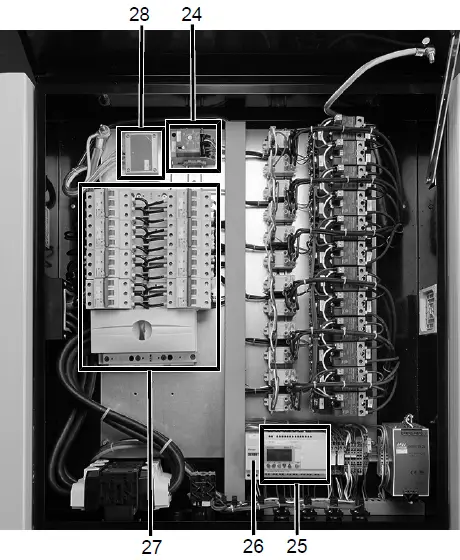
| No. | Designation |
| 24 | Safety temperature limiter with reset switch |
| 25 | Control |
| 26 | Analogous operating hours counter |
| 27 | Fuses |
| 28 | Pressure sensor |
Opening the electrical control box
The electrical control box may only be opened by instructed persons. Only a qualified electrician is allowed to perform repair work on the electrical system.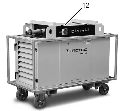
- Open the cover flap at the electrical control box (12).
Overtemperature protection
For overheating protection the electric heater comes equipped with several safety elements: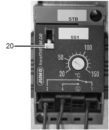
- Disconnection of the electric heating from the mains when falling below the minimum air volume.
- Reduction of the maximum air outlet temperature at approx. 65°C.
- Rundown operation of the fan after switch-off to dissipate the accumulated heat at the electric heating until the air outlet temperature has dropped to below 40 °C.
- Switch-off of the device by means of a safety temperature limiter.
- The safety temperature limiter (24) can only be reset by actuating the integrated reset switch (20). This switch is located on the left side of the electrical control box.
Control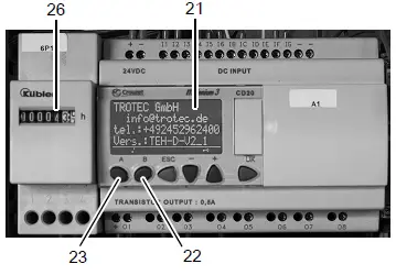
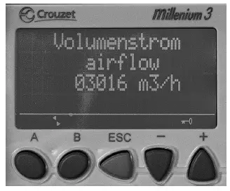
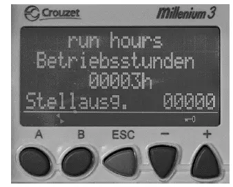
The control unit is located inside the electrical control box (12). In order to operate or read the control unit, the electrical control box (12) needs to be opened first. The control unit’s display (21) provides further information regarding the operating condition of the device, current parameters (volumetric flow, pressure, temperature) as well as any pending fault messages. The control unit ensures the constant regulation of the volumetric flow, even when f.i. connecting different hose lengths. From the start screen the buttons A (23) and B (22) can be used to browse through the menu. The operating hours counter (26) is located beside the control unit. In order to read the operating hours counter, the electrical control box (12) needs to be opened first.
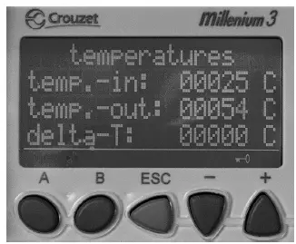
The following parameters can be called up
- Volumetric flow in m3/h (airflow):

- Input temperature in °C (temp.-in),
- Output temperature in °C (temp.-out),
- Output temperature in °C (delta-T):

- Digital operating hours display in h (run hours)

Errors and faults
The device has been checked for proper functioning several times during production. If malfunctions occur nonetheless, check the device according to the following list. The STÖRUNG-FAULT lamp (19) lights up directly after switch-on of the device:
- Aborted rundown from previous operation, which has led to tripping of the safety temperature limiter. Actuate the reset switch (20) of the safety temperature limiter and restart the device.
- Malfunction in the software of the control unit or the frequency converter (optional), which prevents the device from starting. Acknowledge the fault by means of the AUSOFF button (15). If the STÖRUNG-FAULT lamp (19) continues to be illuminated, switch the device off via the emergency stop main switch (9) and back on again after approx. 10 seconds.
The STÖRUNG-FAULT lamp (19) lights up during operation
- Insufficient air flow rate:
- Check whether the filter is clogged. Replace the filter if necessary.
- Check whether the air resistance in the ensuing air line is too high (length, bends, foreign objects etc.). Reduce the air resistance if necessary.
- No sign of heating:
- The heating may be defective. Have the heating repaired by a qualified electrician.
- The air flow rate may be too low. See fault Insufficient air flow rate.
- Thermostat tripped:
- The air flow rate may be too low. See fault Insufficient air flow rate.
- The thermostat may be defective. Have the thermostat replaced by a qualified electrician.
- An error in the sensor circuit may have occurred. Have the sensor circuit checked by a qualified electrician.
- There was a temporary mains voltage drop or power failure and a consequent failure of the rundown function.
- Actuate the reset switch (20) of the safety temperature limiter and restart immediately. If no warmth is required, set the selection step switch to position 0.
- Electric installation:
- One or several electrical components may have failed.
- Have the electric installation checked and, if required, defective parts replaced by a qualified electrician.
- Pressure sensor tripped:
- The minimum air volume was not reached. See fault Insufficient air flow rate.
Faults control unit
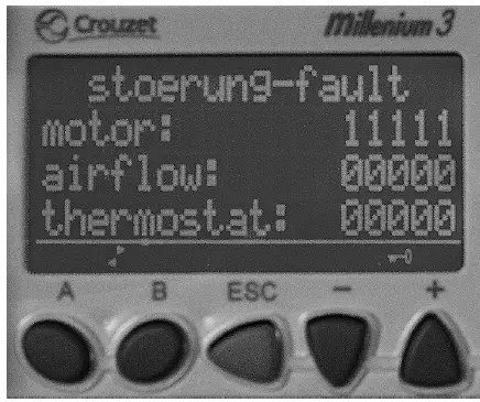
In order to read the fault messages on the display (21) of the control unit, the electrical control box needs to be opened. The STÖRUNG-FAULT lamp (19) also serves as collective fault message for the control. The following fault messages will be indicated in detail on the display (21) of the control unit:
- Motor or fan fault.

- Fault in the air volume flow:

- Pressure sensor has tripped.
- Critical overtemperature:

- Safety temperature limiter has tripped.
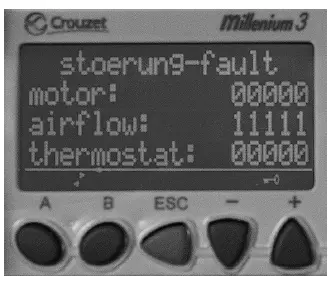
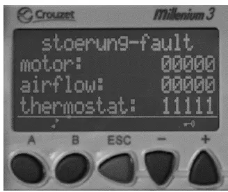
Note: In case of all faults the heating is switched off, but not disconnected from the mains. After the elimination of the fault, acknowledge it using the AUS-OFF button (15) (reset).
The device still does not operate correctly after these checks: Please contact the customer service. If necessary, bring the device to an authorised specialist electrical company or to Trotec for repair.
Maintenance
Trotec electric heaters are designed for long hours of operation with minimum maintenance effort. Safe operation of the device requires all built-in components, especially the safety temperature limiter (STB), to be checked and cleaned after 6 months at the latest or after every 4,000 operating hours as well as all damaged components to be replaced. Prior to cleaning the interior, protect the fan and further electrical components from water ingress with appropriate means.
Maintenance intervals
| Maintenance and care interval | before every start-up | as needed | at least every 2 weeks | at least every 4 weeks | at least every 6 months | at least annually |
| Check air inlets and outlets for dirt and foreign objects and clean if necessary | X | |||||
| Clean the exterior | X | X | ||||
| Visually check the inside of the device for dirt | X | X | ||||
| Check air inlet grid and air filter for dirt and foreign objects and clean or replace if necessary | X | X | ||||
| Replace the air filter | X | |||||
| Check for damage | X | |||||
| Checking the safety temperature limiter | X | |||||
| Check the attachment screws | X | X | ||||
| Test run | X |
Maintenance and care log
- Device type: ………………………………………
- Device number: ………………………………
| Maintenance and care interval | 1 | 2 | 3 | 4 | 5 | 6 | 7 | 8 | 9 | 10 | 11 | 12 | 13 | 14 | 15 | 16 |
| Checking of air inlets and outlets for dirt and foreign objects and cleaning if necessary | ||||||||||||||||
| Cleaning the exterior | ||||||||||||||||
| Visual inspection of the inside of the device for dirt | ||||||||||||||||
| Checking of air inlet grid and air filter for dirt and foreign objects and cleaning or replacement if necessary | ||||||||||||||||
| Air filter replacement | ||||||||||||||||
| Checking for damage | ||||||||||||||||
| Checking of attachment screws | ||||||||||||||||
| Test run | ||||||||||||||||
| Remarks: |
| 1. Date: …………………………….. Signature: ………………………….. | 2. Date: ……………………………… Signature: …………………………… | 3. Date: ……………………………… Signature: …………………………… | 4. Date: ……………………………… Signature: …………………………… |
| 5. Date: …………………………….. Signature: ………………………….. | 6. Date: ……………………………… Signature: …………………………… | 7. Date: ……………………………… Signature: …………………………… | 8. Date: ……………………………… Signature: …………………………… |
| 9. Date: …………………………….. Signature: ………………………….. | 10. Date: ……………………………. Signature: …………………………… | 11. Date: ……………………………. Signature: …………………………… | 12. Date: ……………………………. Signature: …………………………… |
| 13. Date: …………………………… Signature: ………………………….. | 14. Date: ……………………………. Signature: …………………………… | 15. Date: ……………………………. Signature: …………………………… | 16. Date: ……………………………. Signature: …………………………… |
Activities required before starting maintenance
- Switch the device off.
- Switch off the device at the main switch.
- Wait for the end of the rundown period if the device was in operation beforehand.
- Hold onto the mains plug while pulling the power cable out of the mains socket.
Warning of electrical voltage
- Maintenance tasks and repair work may only be performed by qualified electricians or Trotec.
Cleaning the housing
Clean the housing with a soft, damp and lint-free cloth. Make sure that no moisture enters the housing. Protect electrical components from moisture. Do not use any aggressive cleaning agents such as cleaning sprays, solvents, alcohol-based or abrasive cleaners to dampen the cloth. Wipe the housing dry after cleaning.
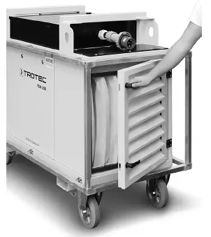
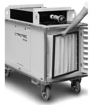
Changing the filter
The filter change intervals depend on the degree of air pollution and the filter quality. Dirty filters impair the performance ability of the electric heater. Therefore, in case of heavily contaminated intake air, they are to be inspected at least once a week, otherwise at least monthly and replaced whenever necessary.
- Open the weather protection grid by means of the two handles.

- Remove the bag filter.

- Install the new bag filter.
- Then close the weather protection grid again.
Technical annex
Technical data
| Parameter | Value | |||
| Model (version 3.0) | TEH 200 | TEH 300 | TEH 400 | |
| Article number | 1.410.000.150 | 1.410.000.155 | 1.410.000.160 | |
| Max. amount of air | 3000 m3/h | 6000 m3/h | 9000 m3/h | |
| Heating capacity | 40 kW (34,394 kcal) | 80 kW (68,788 kcal) | 120 kW (103,181 kcal) | |
| Air pressure (max. compression) | 600 Pa | 600 Pa | 600 Pa | |
| Max. air outlet temperature * | 65 °C | 65 °C | 65 °C | |
| Max. temperature increase (ΔT) | 60 °C | 60 °C | 60 °C | |
| Permissible intake temperature | -20 °C to max. +40 °C | -20 °C to max. +40 °C | -20 °C to max. +40 °C | |
| Control | 8-step selection switch for air flow rate and temperature | |||
| Stage 0 | Air flow rate | 3000 m3/h | 6000 m3/h | 9000 m3/h |
| Temperature increase (ΔT) | – | – | – | |
| Level 1 | Air flow rate | 3000 m3/h | 6000 m3/h | 9000 m3/h |
| Temperature increase (ΔT) | 15 °C | 15 °C | 15 °C | |
| Level 2 | Air flow rate | 3000 m3/h | 6000 m3/h | 9000 m3/h |
| Temperature increase (ΔT) | 25 °C | 25 °C | 25 °C | |
| Level 3 | Air flow rate | 3000 m3/h | 6000 m3/h | 9000 m3/h |
| Temperature increase (ΔT) | 40 °C | 40 °C | 40 °C | |
| Level 4 | Air flow rate | 2000 m3/h | 4000 m3/h | 6000 m3/h |
| Temperature increase (ΔT) | – | – | – | |
| Level 5 | Air flow rate | 2000 m3/h | 4000 m3/h | 6000 m3/h |
| Temperature increase (ΔT) | 20 °C | 20 °C | 20 °C | |
| Level 6 | Air flow rate | 2000 m3/h | 4000 m3/h | 6000 m3/h |
| Temperature increase (ΔT) | 40 °C | 40 °C | 40 °C | |
| Level 7 | Air flow rate | 2000 m3/h | 4000 m3/h | 6000 m3/h |
| Temperature increase (ΔT) | 60 °C | 60 °C | 60 °C | |
| Input voltage | 3~/PE – 400 V / 50-60 Hz | 3~/PE – 400 V / 50-60 Hz | 3~/PE – 400 V / 50-60 Hz | |
| Max. current consumption | 61 A (41.5 kW) | 123 A (84 kW) | 182 A (125.5 kW) | |
| Fusing / mains connection | 63 A / CEE 63 A, 5-pin | 125 A / CEE 125 A, 5-pin | 200 A termination | |
| Sound level (at a distance of 3 m) | 75 dB(A) | 76 dB(A) | 78 dB(A) | |
| Hose connector | Ø 450 mm | Ø 450 mm | Ø 600 mm | |
| Suitable for hose lengths to | 100 m | 100 m | 100 m | |
| Mobility | wheeled / forklift / crane | wheeled / forklift / crane | wheeled / forklift / crane | |
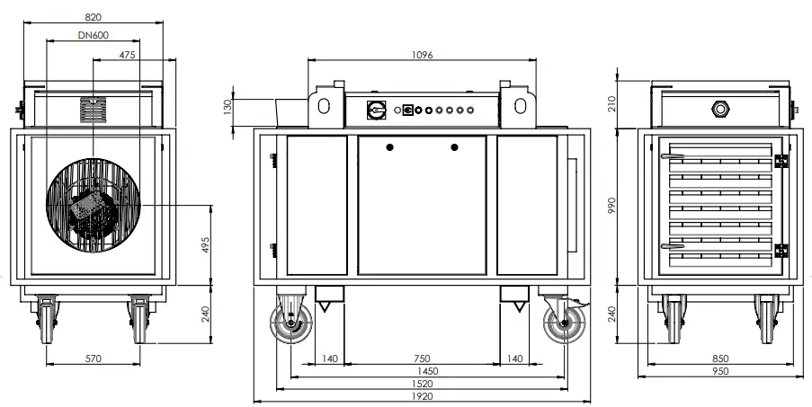
| Dimensions (length x width x height) | 1,625 x 800 x 1,270 (mm) | 1,625 x 800 x 1,270 (mm) | 1,920 x 950 x 1,450 (mm) | |
| Weight | 280 kg | 310 kg | 460 kg | |
| Cable cross-section, min. | 16 mm2 | 50 mm2 | 95 mm2 | |
| Overheating protection | yes | yes | yes | |
| Minimum distance to all sides during operation and maintenance | 1 m | 1 m | 1 m | |
| * The maximum air outlet temperature of the standard version is automatically electronically limited to 65 °C. Other versions with higher air outlet temperatures are optionally available on request. ** All of the technical data +/- 10 %. | ||||
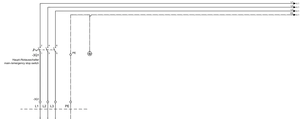
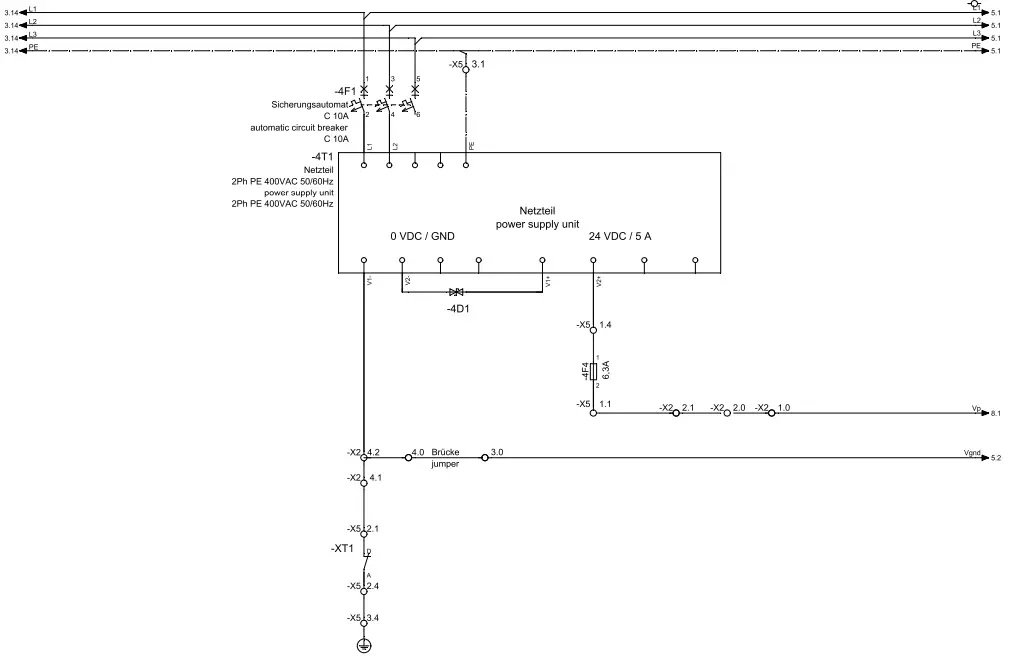
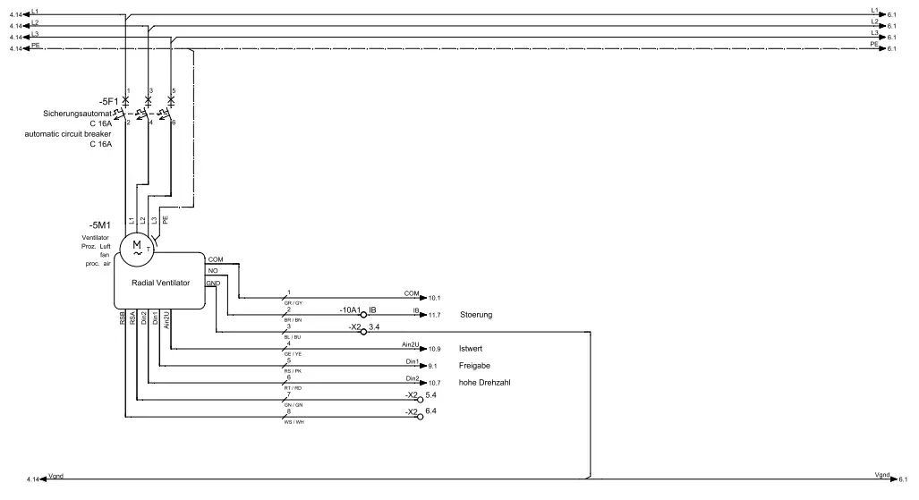
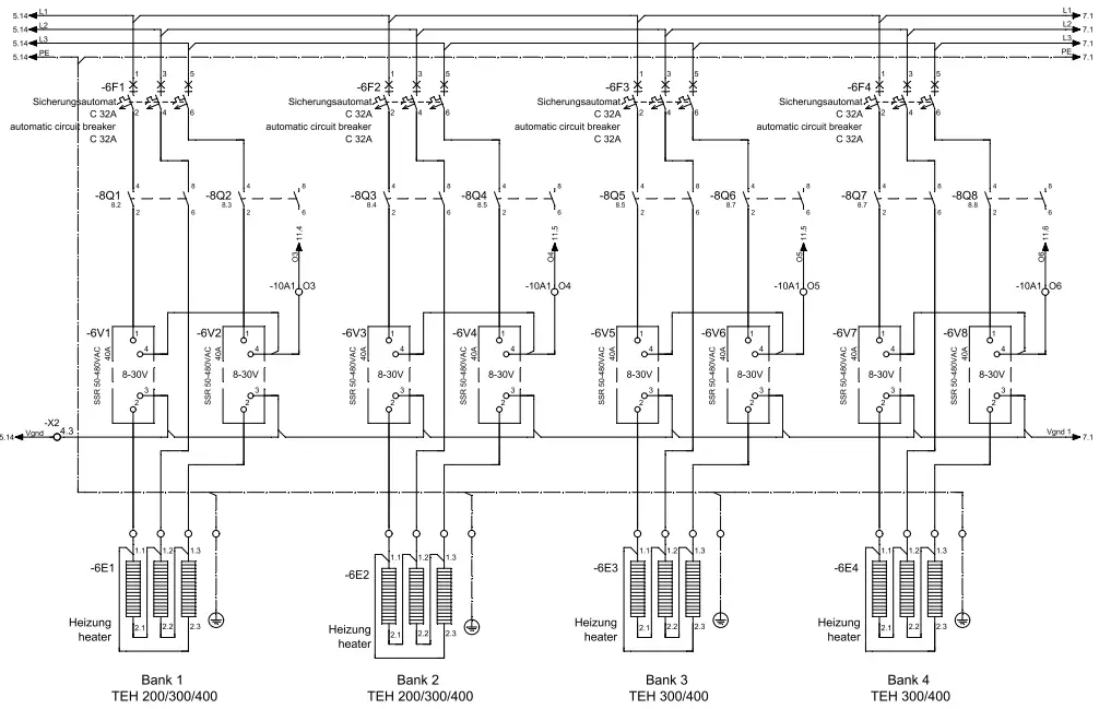
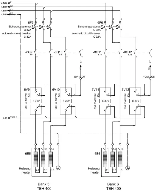
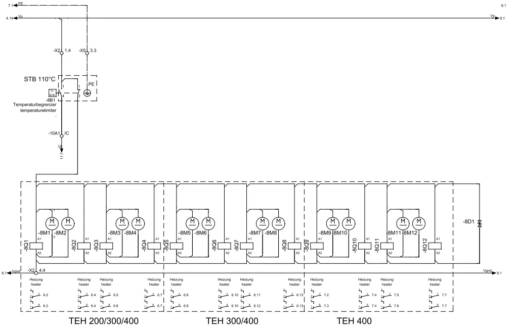
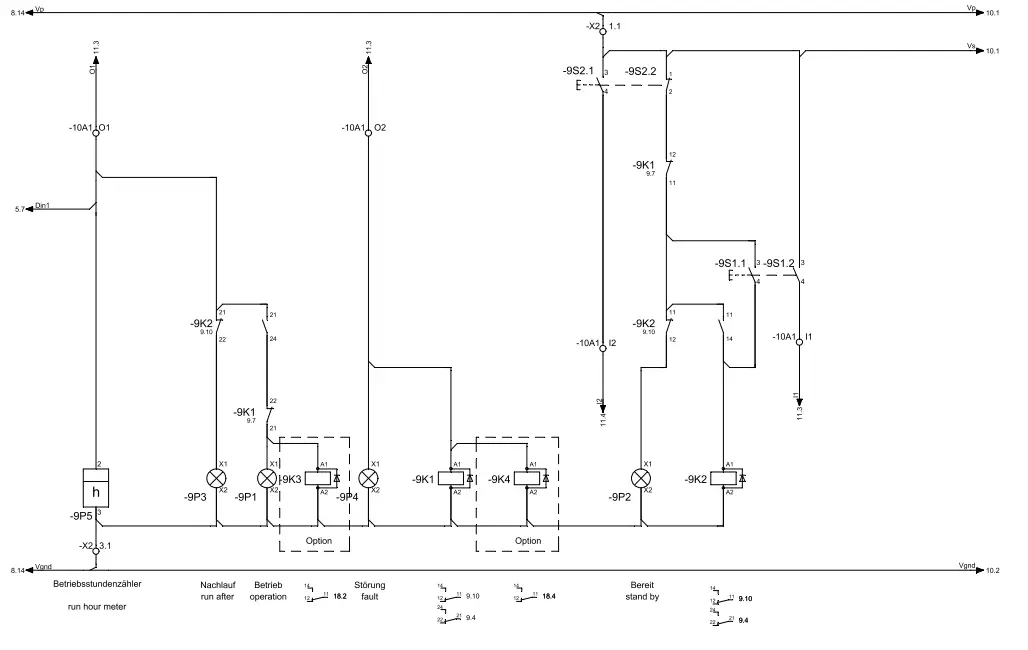
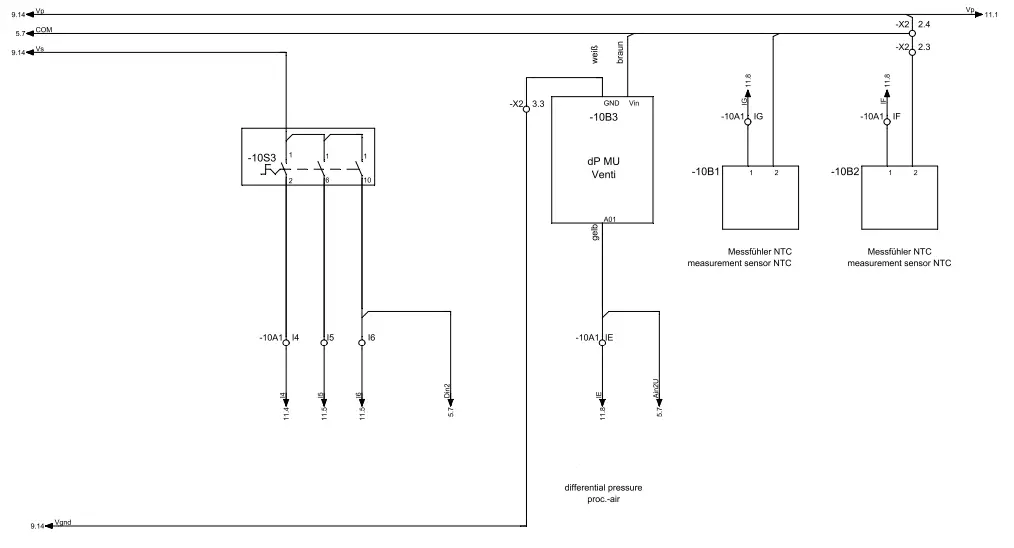
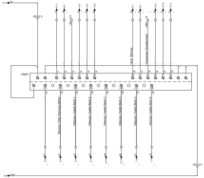
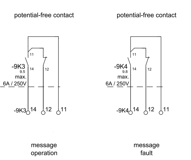
Circuit diagram TEH 200/300/400
Project data
- Series: TEH
- Drawing number: EEA-100-0153-02
- Model: TEH 200/300/400
- Editor: ………………………
- checked: ………………………
- Date: 09/03/2018
- Customer: ………………………..
- customer number: ………………………..
- project number: ………………………..
TROTEC drawing numbers
EEA-100-0153-02 TEH 200/300/400 Series 08/2018
- Regulation: VDE
- Feed: 3x 400V 50/60Hz +PE
- Control voltage: 24V DC
- TEH 400 rated output: 125.5 kW
- TEH 400 current consumption: nEn 182.0A (@ 400V)
- TEH 300 rated power: 83.47 kW
- TEH 300 current consumption: INOM 123.0A (@ 400V)
- TEH 200 rated output: 41.65 kWV
- TEH 200 current consumption: INOM 61.0A (@ 400V)
Dimensional drawing TEH 200/300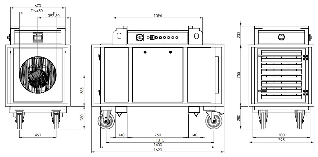
Dimensional drawing TEH 400
Exploded assembly drawing
Info: The position numbers of the spare parts differ from those describing the positions of the components mentioned in these instructions.
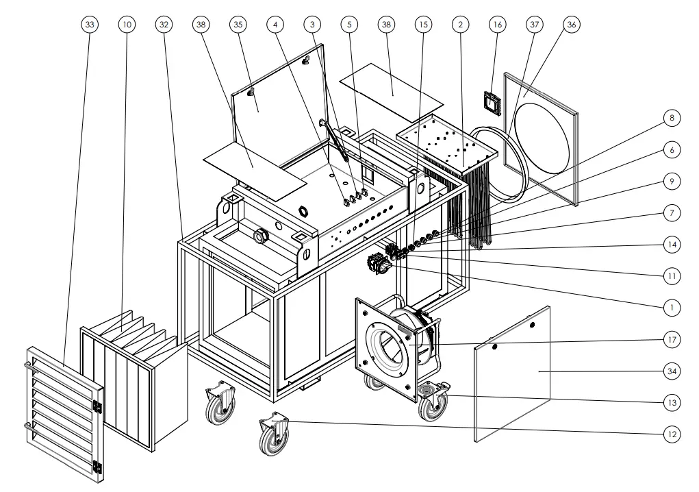
List of spare parts
| Spare parts | TEH 200 | TEH 300 | TEH 400 | ||
| Item | Designation | Quantity | Trotec no. | Trotec no. | Trotec no. |
| 1 | Main switch | 1 | P 1000 1454 | P 1000 1454 | P 1000 1532 |
| 2 | Heating elements | 6 x P 1000 1905 | 12 x P 1000 1905 | 18 x P 1000 1905 | |
| 3 | LED element white 24 V | 2 | P 1000 1447 | P 1000 1447 | P 1000 1447 |
| 4 | LED element green 24 V | 1 | P 1000 1445 | P 1000 1445 | P 1000 1445 |
| 5 | LED element red 24 V | 1 | P 1000 1446 | P 1000 1446 | P 1000 1446 |
| 6 | Indicator light yellow | 1 | P 1000 1450 | P 1000 1450 | P 1000 1450 |
| 7 | Indicator light green | 1 | P 1000 0244 | P 1000 0244 | P 1000 0244 |
| 8 | Indicator light red | 1 | P 1000 1448 | P 1000 1448 | P 1000 1448 |
| 9 | Indicator light white | 1 | P 1000 1449 | P 1000 1449 | P 1000 1449 |
| 10 | Air filter | 1 | P 1000 1563 | P 1000 1563 | 1 x P 1000 1563 1 x P 1000 1564 |
| 11 | Cam switch | 1 | P 1000 1455 | P 1000 1455 | P 1000 1455 |
| 12 | Trestle roller | 2 | P 1000 1394 | P 1000 1394 | P 1000 1394 |
| 13 | Lockable swivel castor | 2 | P 1000 1393 | P 1000 1393 | P 1000 1393 |
| 14 | Push button green | 1 | P 1000 1443 | P 1000 1443 | P 1000 1443 |
| 15 | Push button red | 1 | P 1000 1444 | P 1000 1444 | P 1000 1444 |
| 16 | Control cabinet filter TEH | 1 | P 1000 1392 | P 1000 1392 | P 1000 1392 |
| 17 | Radial fan | 1 | P 1000 1383 | P 1000 1994 | P 1000 1384 |
| 18 | Relay | 2 | P 1000 6608 | P 1000 6608 | P 1000 6608 |
| 19 | Operating hours counter | 1 | P 1000 1477 | P 1000 1477 | P 1000 1477 |
| 20 | Lateral insulation Base insulation | 2 x P 1000 1989 2 x P 1000 1509 | 2 x P 1000 1989 2 x P 1000 1509 | 2 x P 1000 1512 2 x P 1000 1511 | |
| 21 | Pressure sensor | 1 | P 1000 1388 | P 1000 1388 | P 1000 1388 |
| 22 | Semi-conductor relay | 4 x P 1000 1431 | 8 x P 1000 1431 | 12 x P 1000 1431 | |
| 23 | Load relay 24 V | 4 x P 1000 1238 | 8 x P 1000 1238 | 12 x P 1000 1238 | |
| 24 | Power adapter | 1 | P 1000 1313 | P 1000 1313 | P 1000 1313 |
| 25 | Safety temperature limiter | 1 | P 1000 1432 | P 1000 1432 | P 1000 1432 |
| 26 | Fuse C 10 A | 1 | P 1000 4058 | P 1000 4058 | P 1000 4058 |
| 27 | Fuse C 16 A | 1 | P 1000 4057 | P 1000 4057 | P 1000 4057 |
| 28 | Fuse B 32 A | 2 x P 1000 4056 | 4 x P 1000 4056 | 6 x P 1000 4056 | |
| 29 | Temperature probe | 1 | P 1000 1430 | P 1000 1430 | P 1000 1430 |
| 30 | Temperature probe | 1 | P 1000 1429 | P 1000 1429 | P 1000 1429 |
| 31 | Isolating terminal | 1 | P 1000 1561 | P 1000 1561 | P 1000 1561 |
| 32 | Protective frame (incl. mounting brackets) | 1 | P 1000 6972 | P 1000 6972 | P 1000 6973 |
| 33 | Air filter inspection door | 1 | P 1000 6974 | P 1000 6974 | P 1000 6975 |
| 34 | Fan cover | 2 | P 1000 6976 | P 1000 6976 | P 1000 6977 |
| 35 | Control cabinet cover | 1 | P 1000 6978 | P 1000 6978 | P 1000 6979 |
| 36 | E-heater cover | 1 | P 1000 6980 | P 1000 6980 | P 1000 6981 |
| 37 | Spigot | 1 | P 1000 1386 | P 1000 1386 | P 1000 1387 |
| 38 | Cover | 2 | P 1000 1982 | P 1000 1982 | P 1000 1983 |
Disposal
Always dispose of packing materials in an environmentally friendly manner and in accordance with the applicable local disposal regulations.
The icon with the crossed-out waste bin on waste electrical or electronic equipment stipulates that this equipment must not be disposed of with the household waste at the end of its life. You will find collection points for free return of waste electrical and electronic equipment in your vicinity. The addresses can be obtained from your municipality or local administration. You can also find out about other return options that apply for many EU countries on the website https://hub.trotec.com/?id=45090. Otherwise, please contact an official recycling centre for electronic and electrical equipment authorised for your country. The separate collection of waste electrical and electronic equipment aims to enable the re-use, recycling and other forms of recovery of waste equipment as well as to prevent negative effects for the environment and human health caused by the disposal of hazardous substances potentially contained in the equipment.
Only for United Kingdom
According to Waste Electrical and Electronic Equipment Regulations 2013 (2013/3113) devices that are no longer usable must be collected separately and disposed of in an environmentally friendly manner.
Declaration of conformity
Declaration of conformity in accordance with the EC Machinery Directive 2006/42/EC, Annex II, Part 1, Section A We – Trotec GmbH – declare in sole responsibility that the product designated below was developed, constructed and produced in compliance with the requirements of the EC Machinery Directive in the version 2006/42/EC.
- Product model/product: TEH 200
- TEH 300
- TEH 400
- Product type: electric heater
- Year of manufacture as of: 2022
Relevant EU directives
- 2011/65/EU: 01/07/2011
- 2014/30/EU: 29/03/2014
Applied harmonised standards
- EN ISO 12100:2010
- EN ISO 13849-1:2015
- EN ISO 13857:2019
- EN 55011:2016
- EN 55011:2016/A1:2017
- EN 55011:2016/A11:2020
- EN 60204-1:2018
- EN 60335-1:2012
- EN 60335-1:2012/A11:2014
- EN 60335-1:2012/A13:2017
- EN 60335-1:2012/AC:2014
- EN 60335-1:2012/A15:2021
- EN 61000-6-1:2007
- EN 61000-6-3:2007
- EN 61000-6-3:2007/A1:2011
- EN 61000-6-3:2007+A11:2011+AC:2012
Applied national standards and technical specifications
- None
Manufacturer and name of the authorised representative of the technical documentation
- Trotec GmbH
- Grebbener Straße 7, D-52525 Heinsberg
- Phone: +49 2452 962-400
- E-mail: [email protected]
Place and date of issue
Heinsberg, 01.05.2022
Detlef von der Lieck, Managing Director
Trotec GmbH
- Grebbener Str. 7 D-52525 Heinsberg
- +49 2452 962-400
- +49 2452 962-200
- [email protected]
- www.trotec.com
TRT-BA-TEH200-TEH300-TEH400-TC220601TTRT02-005-EN


