
ACiQ-24-AHB Next Gen Ducted Heat Pump System
INSTRUCTION
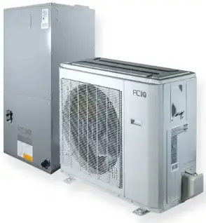
Thank you for purchasing a Next Gen Heat Pump system from ACiQ. This system gives you the benefits of a variable speed, inverter driven heat pump condenser, combined with a smart air handler with a variable speed blower.
This Quick Start Guide covers how to connect the thermostat to your system and ensure proper communication. It is not meant to replace the entire installation manual. Please reference install manual for in depth instructions.
Option 1 – Wiring Diagram When Using Provided Thermostat (Recommended)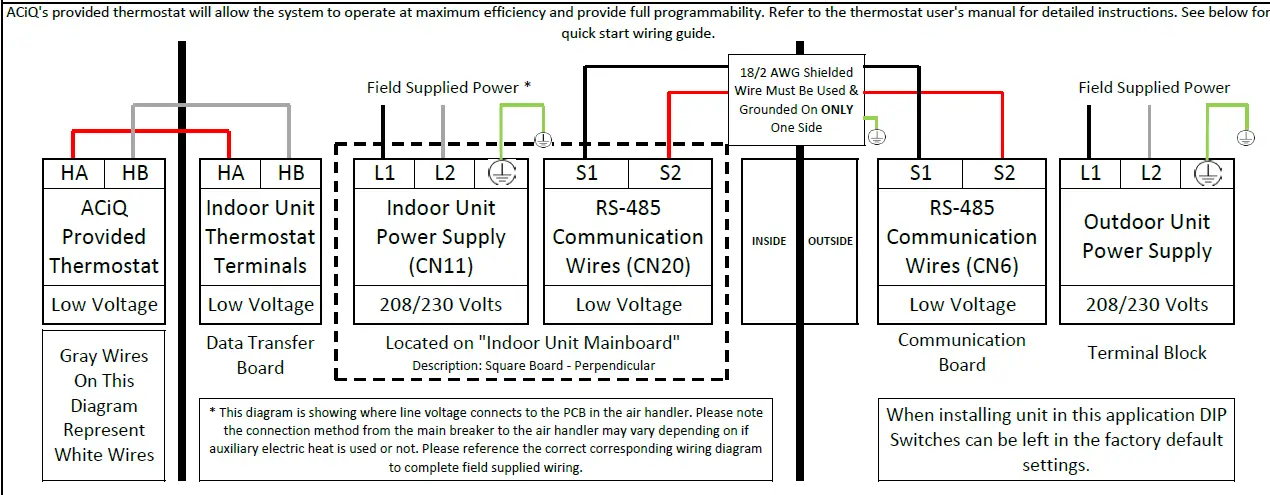
IMPORTANT NOTES
- Communication wire connected to S1 & S2 MUST be 18/2 AWG shielded cable. Failure to use specified wire can result in communication errors.
- The drain wire must be grounded at one end ONLY and the shield foul and conductor MUST be trimmed back and insulated at the other end. DO NOT ground the shield at both ends. Failure to follow this procedure can result in communication errors.
- Communication wire must be run a minimum of 18″ away from any line voltage wires. Failure to follow this procedure can result in communication errors.
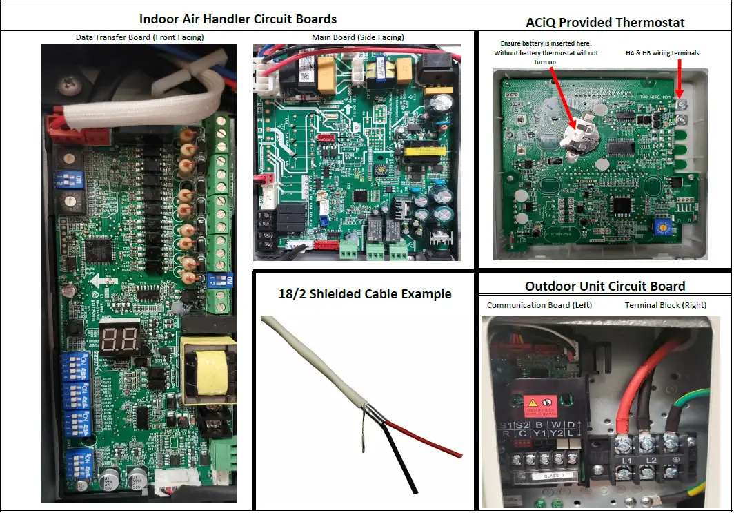
Photo Examples
IMPORTANT INSTALL INFORMATION
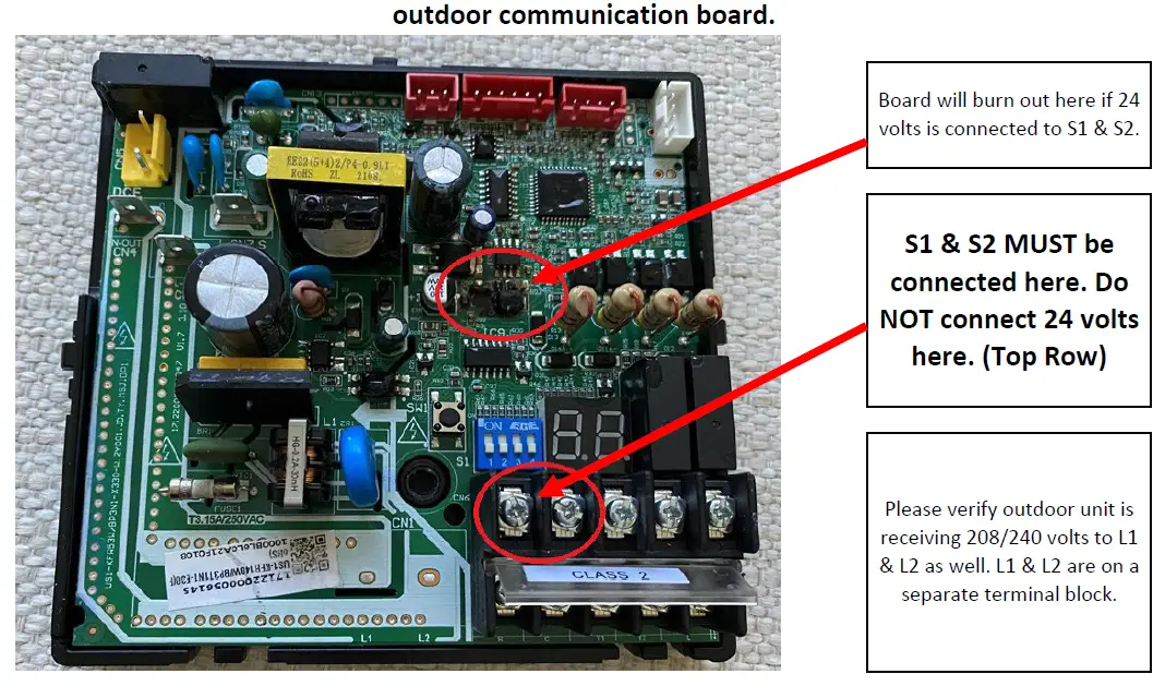
S1 & S2 terminals are on top. R & C terminals are on the bottom.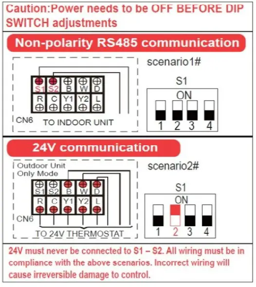
To address this issue moving forward the new cover will look as shown below. If you have the old version use the picture below for a reference.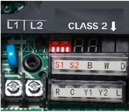
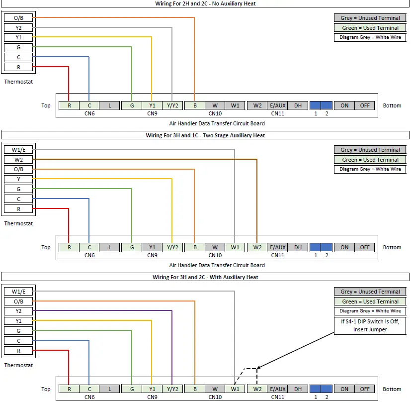
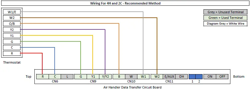
Option 2 – Connecting a 3rd Party 24 Volt Thermostat With Communication Wire Connected
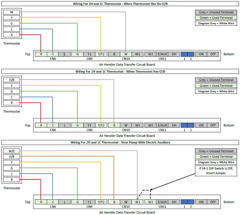
Any 24 volt thermostat can be selected. Select the appropriate profile from the options listed below to wire thermostat to air handler. S1 & S2 must be connected at the indoor unit and the outdoor unit. Set the system dip switches as shown below.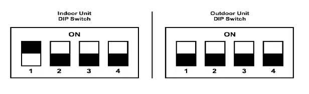
Thermostat Connection (Select One)
AHU DIP Switch Guide
| Function Settings | ||
| SW1-1 | Thermostat Communication Method | |
| OFF | RS-485 Communication. Used For Provided ACiQ Thermostat. | |
| ON | 24 Volts. Used For Third Party Thermostats. | |
| SW1-2 | Cold Air Prevention – Defrost | |
| OFF | Cold Air Prevention Activated – Fan Stops | |
| ON | No Cold Air Prevention – Fan Continues To Operate | |
| SW1-3 | System Type | |
| OFF | Heat Pump | |
| ON | Cooling Only | |
| SW1-4 | Outdoor System Brand | |
| OFF | ACiQ Condenser | |
| ON | Third Party Condenser | |
| Heat Settings | ||
| SW2-1 | Auxiliary Heat Activation Differential | |
| OFF | 4 °F Gap Between T1 & Ts Sensors | |
| ON | 2 °F Gap Between T1 & Ts Sensors | |
| SW2-2 | Auxiliary Heat Activation Delay | |
| OFF | None | |
| ON | Yes | |
| SW2-3 | Auxiliary Heat Activation Delay Time | |
| OFF | 15 Minute Delay (For Electric Heat) | |
| ON | 30 Minute Delay (For Electric Heat) | |
| SW2-4 | Heat Source Lock Outs | |
| OFF | In This Position Electric Heat Lockout Can Be Set Via ENC2 | |
| ON | In This Position Compressor Lockout Can Be Set Via ENC2 | |
ENC2 Dial Referenced In SW2-4. 16 Digits To Select From (0-9, A-F). Lock Out Range = -4 °F to 46 °F. 0 = No Lock Out, 1 = -4 °F Lock Out, F = 46 °F Lock Out. Each Digit Increases Temperature By 3.6 °F. Chart Provides Temperature Rounded To Nearest Whole Number.
| Heat Settings Cont. | ||
| SW3-1 | Ramping Up Algorithm Delay | |
| OFF | 1.5 Hours (Efficiency) | |
| ON | 0.5 Hours (Comfort) | |
| SW3-2 | Y/Y2 Temperature Differential Adjustment | |
| OFF | 3.6 °F (Efficiency) | |
| ON | 1.8 °F (Comfort) | |
| SW3-3 | W2 Temperature Differential Activation | |
| OFF | 6 °F (Efficiency) | |
| ON | 4 °F (Comfort) | |
| SW4 | Electric Heat Nominal CFM Adjustment |
| Available settings are 000/001/010/011. Each digit corresponds with an individual switch position. |
| Heat Settings Cont. | ||
| S4-1 | Aux Heat Control | |
| OFF | W1 & W2 Controlled Separately | |
| ON | W1 & W2 Not Controlled Separately | |
| S4-2 | Dehumidify Control | |
| OFF | DH Terminal Available To Be Used | |
| ON | DH Terminal Deactivated | |
Default AHU DIP Switch Settings Shown Below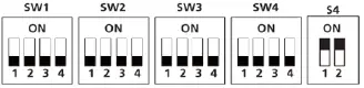
- Delay between 1st stage & 2nd stage electric heat is time based, not temperature based.
- T1 Sensor = Return Air Temp (Room Temp), Ts = Set point
- SW2-3 only works if SW2-2 is turned ON.
- This sets maximum temperature, anything over this setting locks out.
- This sets minimum temperature, anything under this setting locks out.
| 1 = -4 °F | 5 = 10 °F | 9 = 25 °F | D = 39 °F |
| 2 = 0 °F | 6 = 14 °F | A = 28 °F | E = 43 °F |
| 3 = 3 °F | 7 = 18 °F | B = 32 °F | F = 46 °F |
| 4 = 7 °F | 8 = 21 °F | C = 37 °F |
- This sets the maximum continuous runtime allowed before the system automatically stages up capacity. Only applies if 24 volt thermostat is being used.
- If using 24 volt thermostat this sets compressor speed instead. ON = slower, OFF = Faster.
- This DIP switch only works if using the provided communicating ACiQ thermostat. Otherwise delay is time based.
OFF = 0, ON = 1. - For example [SW4-1 OFF, SW4-2 ON, SW4 -3 OFF] = 010
General Notes
If selected 24 volt thermostat has an E/AUX option and it is used to activate heat, all delays will be bypassed.
When auxiliary heat is energized the fan will run in Turbo Mode.
IMPORTANT: In order for changes to take effect power must be OFF BEFORE DIP switch changes.
Please note if using the provided ACiQ thermostat DIP Switch Settings will not need to be adjusted. DIP Switch settings should only be adjusted by a professional HVAC service technician. Please note in this quick start guide the specific DIP Switches that need adjusted will be shown to ensure accurate operation for the chosen set up. For Option 1 nothing needs to be done. For Option 2 please refer to the DIP Switch diagram that shows the correct position of the DIP Switches.Default setting is OFF except S4.


