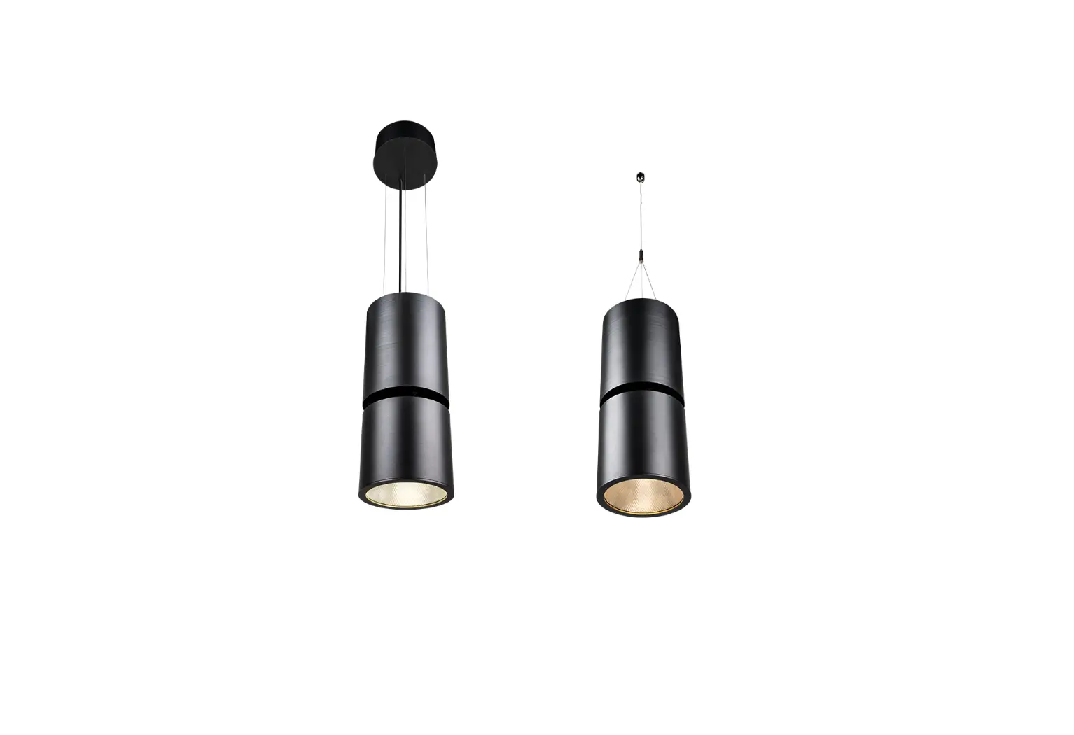
Anolis Ambiane XP56 Pendant Light Instruction Manual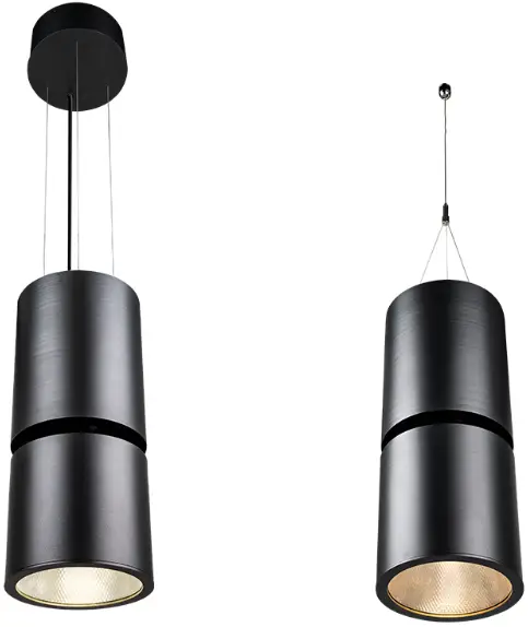
INSTALLATION INSTRUCTIONS
![]() The unit must be installed by a qualified electrician in accordance with all national and local electrical and construction codes and regulations. This device falls under class I and must be grounded!
The unit must be installed by a qualified electrician in accordance with all national and local electrical and construction codes and regulations. This device falls under class I and must be grounded!
STEP 1
DISASSEMBLING OF SUPPLY UNIT
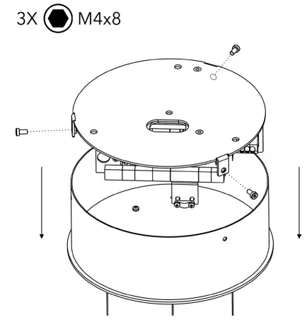
Unscrew three screws on sides of the supply unit and remove the cover.
STEP 2
POWER SUPPLY UNIT REMOVAL
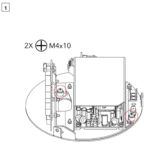
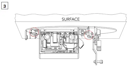
Unscrew the highlighted screws by two full turns to loosen them, but don‘t remove them entirely.
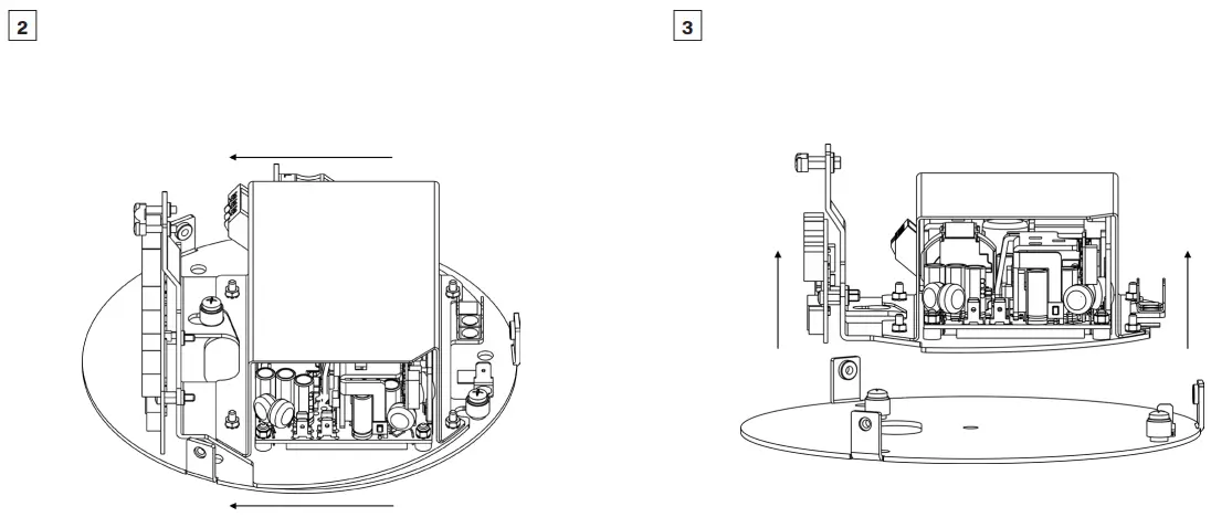
Slide the power supply sideways to a position, where two loosened screws don‘t block the power supply.
Unscrew the highlighted screws by two full turns to loosen them, but don‘t remove them entirely.
STEP 3
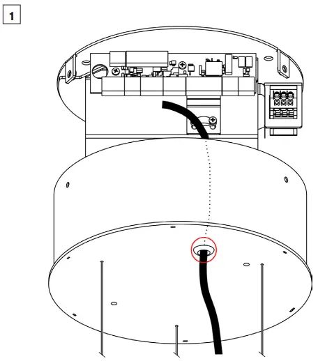
PREPARATION OF MOUNTING HOLES INTO CEILING
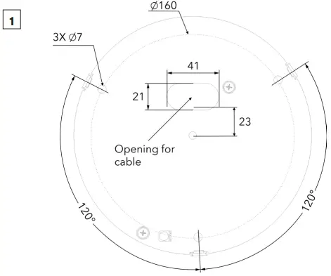
Prepare three holes for base plate mounting and one for power/data cable into the ceiling.
STEP 4
MOUNTING OF BASE PLATE
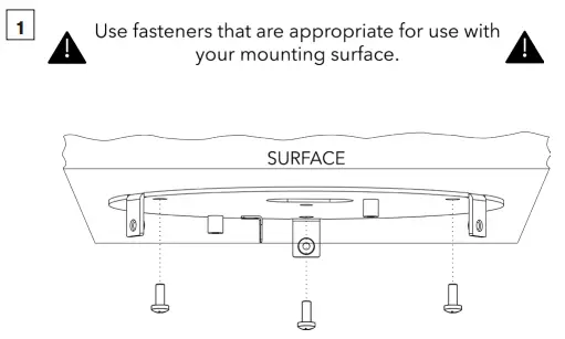
Fasten the Base Plate by means of three screws into prepared holes.
STEP 5
MOUNTING POWER SUPPLY ON THE BASE PLATE
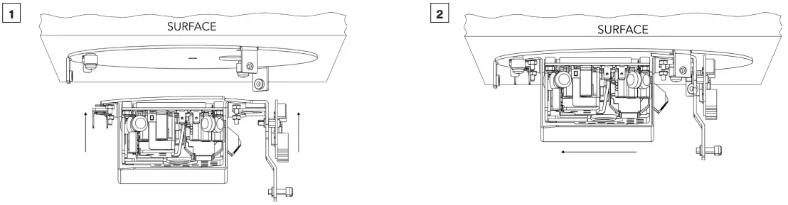
Put the Power Supply back onto the Base Plate.
Slide the Power Supply to its initial position.
Fasten the Power Supply to the base plate by tightening two highlighted screws.
STEP 6
GROUND CONNECTION
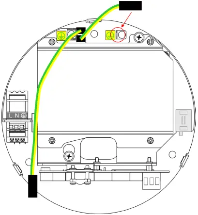
Connect shorter grounding wire to the grounding point on the Base Plate.
STEP 7
PRIMARY POWER CABLE CONNECTION
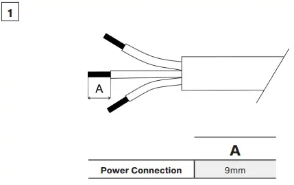
Strip 9 mm of power cable‘s wires.
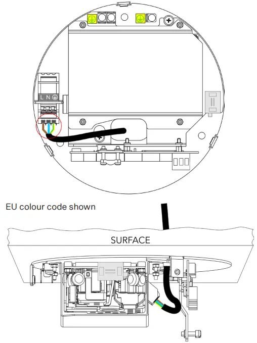
Pull the power cable through prepared hole and connect it to the terminal block on the power Supply.
Power Connection – Power IN
| L | N | GROUND | |
| Core (EU) | Brown | Blue | Green/Yellow |
| Core (US) | Black | White | Green |
STEP 8
LED UNIT CABLE CONNECTION
Shorten the LED unit‘s cable to necessary length and insert it via rubber grommet in the Base Cover.
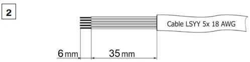
Strip these lengths for cable connections.
LED Unit Connection
| TERMINAL BLOCK | + | A | B | – | GROUND |
| Colour of Wire | Red | White | Blue | Black | Green/Yellow |
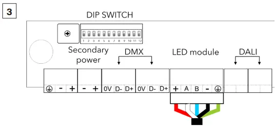
Install terminal block on LED unit‘s cable and connect it to the Control Unit (Supply Unit).
STEP 9
SECONDARY POWER CABLE CONNECTION 48V (PSU SCOPE OF OTHERS)
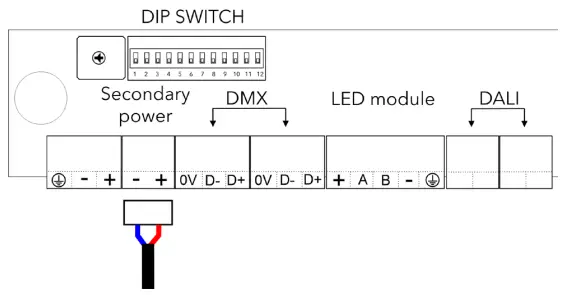
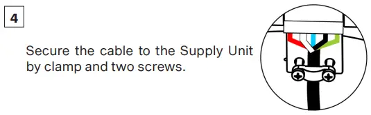
Install terminal blocks on cable and connect it to the control unit.
STEP 10
DATA CABLES CONNECTION (DMX OR DALI)
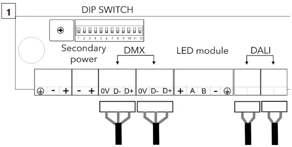
Install terminal blocks on DMX or DALI data cables and connect them to the control unit.
DMX CONNECTION
| 0V | D- | D+ |
| Data Ground | Data – | Data + |
Set the DIP switches to positions according to your operation mode. The fixture can be controlled by DMX or DALI (switch 11 in OFF position).
STEP 11
GROUNDING WIRE CONNECTION TO BASE COVER
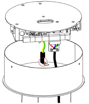
Connect the remaining grounding wire to the grounding point on the Base Cover.
STEP 12
MOUNTING OF BASE COVER
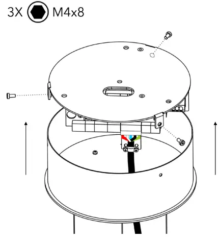
Place the base cover on the base plate and fasten it by means of three screws M4x8.
STEP 13
ADJUSTING THE HANGING WIRE LENGTH
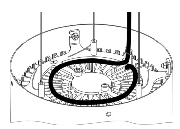
Store redundant cable as instructed on the picture above. Maximum of one full loop to prevent overheating.
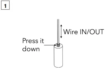
Press down pins on the hanging wires anchors for length adjustment.
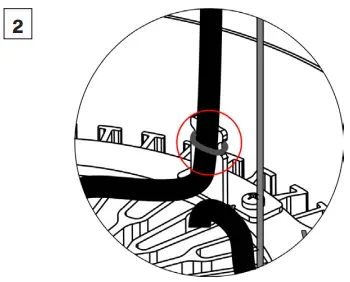
Fasten the LED unit‘s cable to holder using a cable binder.
ROBE lighting s. r. o. | Palackeho 416 | 757 01 Valasske Mezirici | Czech Republic | Tel.: +420 571 751 500 | E-mail: [email protected] | www.anolislighting.com
![]()


