![]() AD-8552EIP Ethernet/IP Converter
AD-8552EIP Ethernet/IP Converter
Instruction Manual
AD-8552EIP Ethernet IP Converter
This manual and Marks
All safety messages are identified by the following, “WARNING” or “CAUTION”, of ANSI Z535.4 (American National Standard Institute: Product Safety Signs and Labels). The meanings are as follows:
| A potentially hazardous situation which, if not avoided, could result in death or serious injury. | |
| A potentially hazardous situation which, if not avoided, may result in minor or moderate injury. |
![]() This is a hazard alert mark.
This is a hazard alert mark.
- This manual is subject to change without notice, at any time, to improve the product.
- The contents of the product specifications and this manual are subject to change without any obligation on the part of the manufacturer.
- Under the copyright laws, the software (program) described in this manual is copyrighted, with all rights reserved.
The software may be installed into one computer and may not be installed into other computers without the prior written consent of A&D Company, Limited. Copying includes translation into another language, reproduction, conversion, photocopy and offer or loan to another person.
Introduction
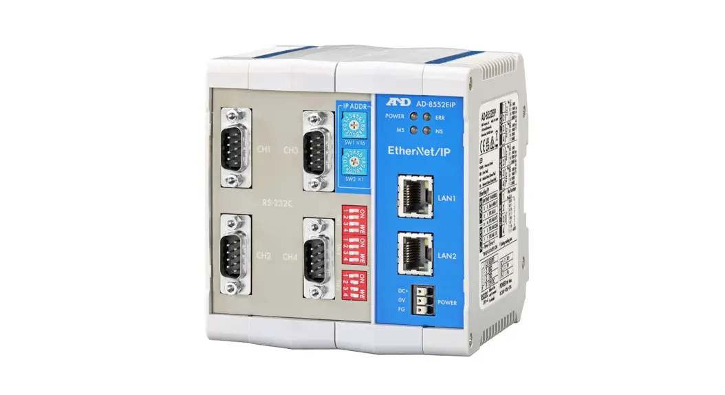
Thank you for purchasing the AD-8552EIP Ether Net/IP converter.
Please read this manual completely before using the AD-8552EIP.
1-1 Features
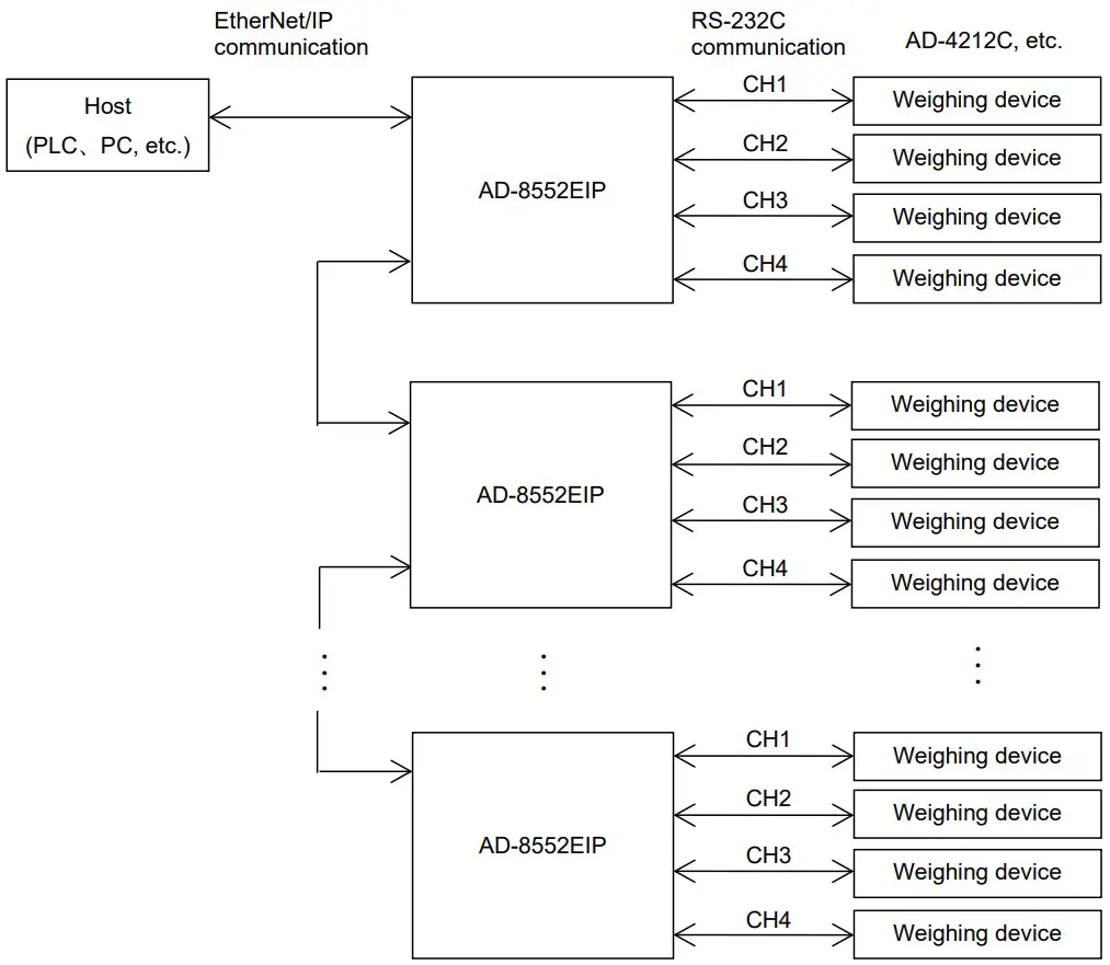
The AD-8552EIP converts the RS-232C communications of the weighing device into Ether Net/IP.
- The measurement value can be reset to zero (re-zero) by operation from the host (PLC or PC).
- hen connected to an AD-4212C and AD-4212D, etc., it is possible to change the response speed, perform calibration with an external weight, and supply power from the weighing device.
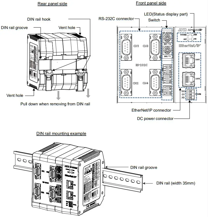
- The hooks on the back of the AD-8552EIP allow one-touch mounting on a DIN rail.
1-2 Cautions
Before use, confirm the following articles for safe operation.
- Grounding The Converter
Be sure to ground this converter.
Separate this earth ground line from others, like ground line of a motor, inverter or a power source. Unless the converter is grounded, it may result in receiving an electric shock, cause operation error or catch fire. - Proper Power Source And Power Cable
Confirm the AC voltage, frequency and power tolerance of the power cable (refer to “4. Power Terminal”). If the voltage range of the cable is lower than the power line voltage, it may cause leakage or catching fire. Use pole compression terminals to connect the power cable to the terminals. - Splashing Water
The module is not water-resistant type. - Flammable Gas
Do not install the converter where flammable gas is present. - Heat Radiation Of The Module
Space out instruments to radiate heat sufficiently.
Do not use in an environment where the ambient temperature exceeds the operating temperature range [-10℃ to +50℃, 85% RH or less (no condensation)].
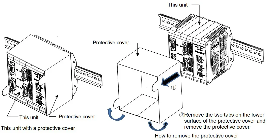
This unit is covered with a transparent plastic protective cover at the time of shipment.
After installing and connecting, be sure to remove the protective cover before turning on the power.
If it is used without removing the protective cover, this unit will overheat.
The protective cover is for preventing the entry of wire scraps and the like during installation and connecting.
Do not remove it until installation and connecting are complete.
Composition and Names
2-1 AD-8552EIP
2-2 Accessories
- Simplified instruction manual
Specifications
| Voltage requirement | 24 VDC external power supply [+ 10%, -15%] |
| Power requirement | 9W Max (When power is supplied to 4 units such as AD-4212C) |
| Communication interface | : Ether Net/IP interface CT18 compliant (For connection with external devices) Refer to “5-1 Ether Net/IP specifications” :RS-232C interface (For connection to weighing device) Refer to “6-1 RS-232C specifications” |
| Communication connector | RJ-45 modular connector (For Ether Net/IP interface) D-Sub 9 pin (male) (For RS-232C interface) |
| Operating condition | 0℃ to + 50℃, Max 85% RH (no condensation) |
| External dimensions | 105 (W) x 112 (H) x 103 (D) mm |
| Mass | Approximately 440g |
3-1 Dimensions

3-2 Applicable models
■ Functions available for each model, accessories needed for connection to AD-8552EIP .
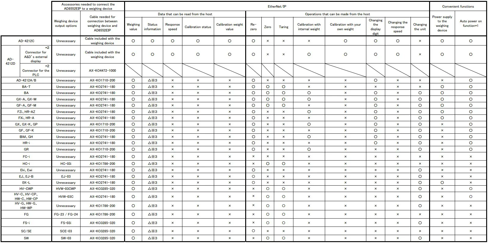
⋆1.If the weighing device does not have an auto power-on function or auto-start function, it is necessary to turn on the display or each weighing device by key operation after turning on the power.
⋆2.The AD4212D has two types of RS-232C connectors. Connect the display connector and the RS-232C connector of AD-8552EIP . (Do not use the PLC connector.)
⋆3.Some functions (calibration error flag) cannot be used.
Power Terminal
4-1 Power-supply voltage
Connect a constant voltage of external power supply (+ 10% -15%) within the range of 24 VDC to the DC power input terminal of the AD-8552EIP.
Caution
- Do not use at a voltage exceeding the rated voltage range (24 VDC +10%-15%)
- Doing so may cause failure or heat generation.
- This unit may not operate normally.
- Ground the FG terminal of the switching power supply used for the power supply of this unit.
● The power line of this unit should be dedicated for this unit, and be separate from other drive devices.
・If strong noise is generated from the power line of another device, this unit may be damaged.
・This unit may not start normally due to the inrush current of other drive devices.
・Depending on the circuit configuration of this unit, other drive devices may not operate normally.
● Select a switching power supply capacity of approximately 9W per unit for the dedicated power supply line for this unit.
・If the power capacity is insufficient, this unit may not operate normally.
■Connector: DC power input terminal

| Signal name | Description |
| DC+ | Power supply 24V input |
| 0V | Power supply 0V input |
| FG | Functional Ground |
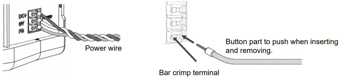
4-2 Connecting example
To insert or remove the wire, press the button part of the connector with a screwdriver or the like.
Modifying the tip of the wire with a bar-type crimp terminal or the like recommended.
Connection conductor specifications
| Clamping range (rating) | 0.20 mm2 to 1.5 mm2 | |
| Applicable wire | AWG | AWG24 to AWG16 |
| Solder plated wire | 0.2 mm2 to 1.5mm2 | |
| Stranded wire | 0.2 mm2 to 1.5mm2 | |
| Bar crimp terminal DIN46228 Part1 | 0.25 mm2 to 1.5mm2 | |
| Bar crimp terminal (With color) DIN46228 Part4 | 0.25 mm2 to 0.75 mm2 | |
| Length | 8mm | |
Ether Net/IP Interface
5-1 Ether Net/IP specifications
■ Connector(RJ-45 modular connector)
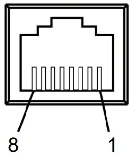
| Pin No. | MDI⋆1 | MDI-X⋆1 |
| 1 | TD+ | RD+ |
| 2 | TD- | RD- |
| 3 | RD+ | TD+ |
| 4 | – | – |
| 5 | – | – |
| 6 | RD- | TD- |
| 7 | – | – |
| 8 | – | – |
| Housing |
RD:Receive data(Input)
TD:Send data(Output)
⋆1.AD-8552EIP is compatible with Auto MDI-X / MDI. The LAN cable can be used either straight or cross.
■ Communication specifications
| Communication standard | EtherNet/IP (CT18 compliant) |
| Vender ID | 188:A&D Company Limited |
| Device type | 43 (0x2B):Generic Device |
| Communication function | Cyclic communication (Implicit message) Message communication (Explicit message) |
| IP address setting method | DIP switch, WEB interface |
| Transmission speed | 10/100Mbps ( Autonegotiation) |
| Communication method | Full duplex / half duplex ( Autonegotiation) |
| Connection form | Star connection, daisy chain connection |
| Connection cable | Shielded twisted pair cable (STP) Straight / Cross, category 5e and above |
5-2 Connections
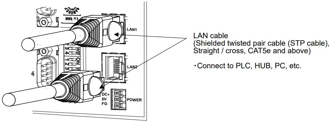
⋆1.LAN cable is not included. Please use a commercially available product.
RS-232C Interface
6-1 RS-232C specifications
■ Connector (D-Sub9 pin, male)
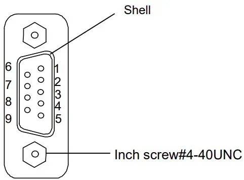
| Pin No. | Signal | Direction | Description |
| 1 | (Vs) | Output | Output of power supply 0V ⋆1 |
| 2 | RXD | Input | Input data |
| 3 | TXD | Output | Output data |
| 4 | – | – | N.C. |
| 5 | SG | – | Signal ground |
| 6 | – | – | N.C. |
| 7 | – | – | N.C. |
| 8 | – | – | N.C. |
| 9 | (Va) | Output | Output of power supply 12V ⋆1 |
| Shell | – | – | Shield |
⋆1.When connected to specific weighing device such as AD-4212C / AD-4212D, Weighing device can be operated by supplying power from the AD-8552 EIP.(Refer to “3-2 Applicable models”)
■ Communication specifications
| Item | Setting |
| Baud rate [SW-3, 4 No.1 to 4] | 2400*, 9600, 19200, 38400bps |
| Data bit | 7 bit (fixed) |
| Parity | EVEN (fixed) |
| Stop bit | 1 bit (fixed) |
| Terminator | <CR><LF> (fixed) |
| Code | ASCII |
6-2 Connecting cable
Connect with a cable applicable to the individual weighing device. Refer to “3-2. Applicable models”.
■ Connection diagram(When connected to a weighing device.)
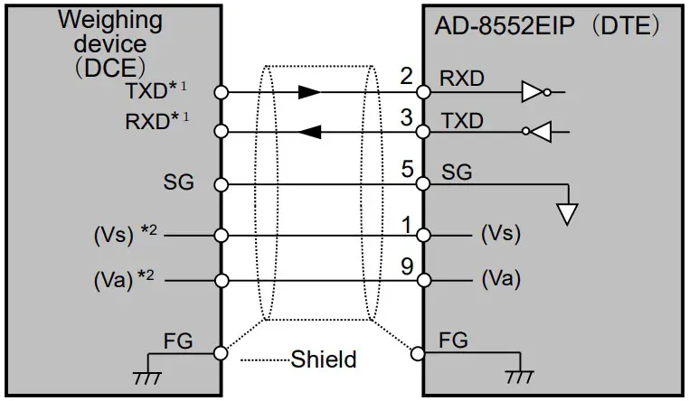
*1. Depending on the weighing device, RXD and TXD may be shown on the opposite side (weighing device output: RXD, weighing device input: TXD)
*2.May vary depending on the weighing device.
Switch
- Set the parameters required for communication using the AD-8552EIP switches (SW-1 to 5).
Caution
- f the setting is changed, be sure to turn on the power off and on again of AD-8552EIP.
When the power is turned on, the switch status is read and applied to operations.
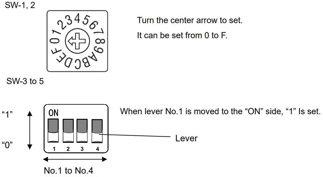
7-1 How to operate the switch
7-2 Factory setting
The switch status and settings at the factory setting are as follows. Refer to “7-3. Ether Net/IP switching settings”
“7-4. RS-232C function settings” for the settings that need to be changed.
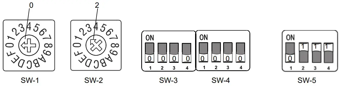
| Item | Factory setting value | Switch status at factory setting | ||
| IP address (4th octet) | 2 | SW-1:0 | SW-2:2 | |
| RS-232C(CH1) baud rate | 2400 | SW-3 No1:0 | SW-3 No2:0 | |
| RS-232C(CH2) baud rate | 2400 | SW-3 No3:0 | SW-3 No4:0 | |
| RS-232C(CH3) baud rate | 2400 | SW-4 No1:0 | SW-4 No2:0 | |
| RS-232C(CH4) baud rate | 2400 | SW-4 No3:0 | SW-4 No4:0 | |
| No Function | SW-5 No1:0 | |||
| Fixed decimal point function | AUTO | SW-5 No2:1 | SW-5 No3:1 | SW-5 No4:1 |
7-3 EtherNet/IP switching settings
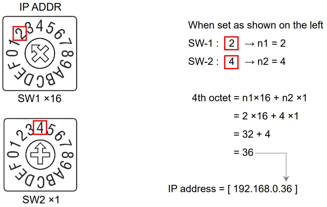
■IP address setting
The IP address allocation can be set within the following range by using the switch (SW-1, 2).
[ 192.168.0.1 ] to [ 192.168.0.254 ], [ 192.168.1.10 ]
(To set an IP address other than the above, refer to “10-4 Network setting screen”.)
| SW-1 | SW-2 | IP address |
| 0 | 0 | Becomes the address set on WEB interface, “10-4. Network setting screen”. |
| 0 | 1 | [ 192.168.0.1 ] |
| 0 | 2 | [ 192.168.0.2 ] |
| n1 | n2 | [ 192.168.0. ( n1×16 + n2×1 ) ] |
| F | E | [ 192.168.0.254 ] |
| F | F | [ 192.168.1.10 ] |
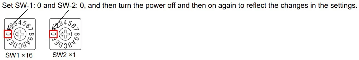
<Setting example>
Caution
- Please consult with your network administrator before connecting to a network.
- Set the IP address so that it does not overlap with other devices.
7-4 RS-232C function settings
■ Communication setting
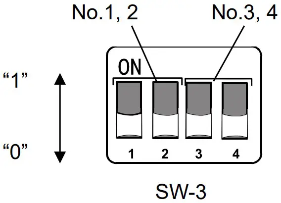
SW-3
| CH1: RS-232C Baud Rate | Setting state | Setting state | CH2: RS-232C Baud rate |
| 2400 bps | 2400 bps | ||
| 9600 bps | 9600 bps | ||
| 19200 bps | 19200 bps | ||
| 38400 bps | 38400 bps |
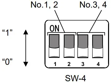
SW-4
| CH3: RS-232C Baud Rate | Setting state | Setting state | CH4: RS-232C Baud Rate |
| 2400 bps | 2400 bps | ||
| 9600 bps | 9600 bps | ||
| 19200 bps | 19200 bps | ||
| 38400 bps | 38400 bps |
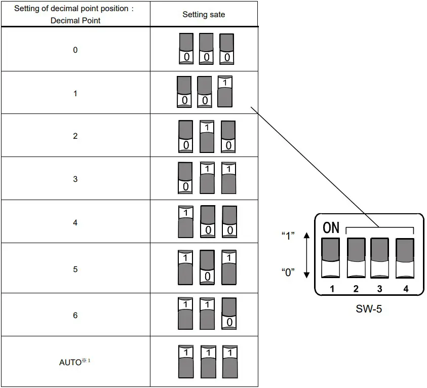
7-5 Fixed decimal point function
- The digits (decimal point position) of the weight value data of EtherNet/IP can be fixed.
- If the connected weighing device has a smart range function, the number of digits after the decimal point is automatically changed.
If you want to fix the number of digits, use the fixed decimal point function.
Example of storage format with fixed decimal point function(Example of CH1)
| Weighing device output value (CH1) | Setting of decimal point position | AD-8552EIP internal data | |
| Weighing value Instance100:byte 0 to 3 [ CH1 Weighing value ] | Decimal point position Instance100:byte 6 to 7 [ CH1 Decimal point position ] | ||
| 123.456g | 2 | 12345 | 2 |
| 3 | 123456 | 3 | |
| AUTO※1 | 123456 | 3 | |
| 123.45g | 2 | 12345 | 2 |
| 3 | 123450 | 3 | |
| AUTO※1 | 12345 | 2 | |
SW-5 No.2 to No.4
⋆1 Depending on the output of the weighing device, the number of digits stored in the weighing value
(Instance100:byte 0 to 3, 18 to 21, 36 to 39, 54 to 57) and the decimal point position (lnstance100:byte 6 to 7, 24 to 25, 42 to 43, 60 to 61) are automatically switched.
LED (status, error display)
POWER ◯ ◯ ERR
MS ◯ ◯ NS
| Display | Function | Color | Status |
| POWER | Power on | Green lit | The AD-8552EIP is powered on. |
| ERR | Error | Red lit | There is something wrong with the AD-8552EIP. |
| MS | Module Status | Off | The AD-8552EIP is not powered on. |
| Green lit | It is working normally. | ||
| Green blink | Not initialized. | ||
| Red lit | An unrecoverable failure has occurred. | ||
| Red blink | A recoverable failure has occurred. | ||
| NS | Network Status | Off | The AD-8552EIP is not powered on. |
| Green lit | The Ether Net/IP connection is established. | ||
| Green blink | The Ether Net/IP connection is not established. | ||
| Red blink | One or more connections have timed out. |
Communication in Ether Net/IP
- When an Ether Net/IP connection is established between the AD-8552EIP and the PLC, data is periodically communicated by cyclic data. Cyclic data consists of “9-2 Output data” and “9-3 Input data”.
- Weighing values can be read and zero reset (rezero) is possible.
- If you are using the following models, you can calibrate (Sensitivity adjustment) via Ether Net/IP.
When calibrating with a weighing device other than the following models, operate with the keys of the weighing device while looking at the display of the measuring instrument.
| Applicable model | Sensitivity adjustment method | Outline of procedure |
| AD-4212C | External weight ⋆1 | While monitoring the balance status with the Input data(Instance100), it is necessary to instruct data acquisition by Output data(Instance150) and to load and unload the weight on the weighing instrument. |
| AD-4212D | External weight ⋆1 | |
| Built-in weight | After instruction by Output data(Instance150), the Input data (Instance100) monitors until calibration is completed. |
⋆1.When changing the weight value to be used, refer to the instruction manual of the individual weighing device.
9-1 Preparing for communication
1. Set the following setting items so that the RS-232C of the weighing instrument and AD-8552EIP are the same.
Reference: AD-4212C/AD-4212D factory setting
| Setting item | Weighing device | AD-8552EIP |
| Baud rate | 2400*, 9600, 19200, 38400 bps | |
| Data bit | 7 bit* | |
| Parity | EVEN* | |
| Stop bit | 1 bit* | |
| Terminator | <CR><LF>* | |
| Data output format | A&D standard format* | ― |
| Data output mode | Settings for continuous output of weighing values.(stream mode*) | ― |
*AD-8552EIP factory setting(normally, the factory setting of AD-4212C / AD-4212D is the same.)
2. Set the following setting items so that the host (PLC, PC, etc.) and AD-8552EIP are the same.
<Setting example>
| Setting item | Host(PLC, PC, etc.) | AD-8552EIP |
| IP address* | [192.168.0.1] | [192.168.0.2] |
* Make sure that IP addresses do not overlap in the connected network.
3. Refer to ”4-2 Connecting example”, “5-2 Connections”, “6-2 Connecting cable” for connecting.
・Normally, when using the AD-4212C/AD-4212D, power can be supplied from the RS-232C terminal, so connecting to the power terminal of the AD-4212C/AD-4212D is not required.
・ When connecting to the AD-4212D, connect to the AD-8552EIP using the AD-4212D display connector.
4. Turn on the device power.
9-2 Output data (Instance150)
The data transferred from PLC etc. to the AD-8552EIP is called Output data.
Output data is used when outputting a command to the measuring instrument.
■ Output data layout (O->T) [ PLC etc. -> AD8552EIP -> Weighing device(CH1 to 4) ]
| Assembly Instance | Attribute | Byte | Name | Data type | Contents |
| 150 | 3 | 0,1 | CH1 Command | UInt16 | Command outpu(t Weighing device CH1) |
| 2,3 | CH2 Command | UInt16 | Command outpu(t Weighing device CH2) | ||
| 4,5 | CH3 Command | UInt16 | Command outpu(t Weighing device CH3) | ||
| 6,7 | CH4 Command | UInt16 | Command outpu(t Weighing device CH4) |
■ Details of the Output data
・Command output [CH1~4 Command] (CH1:byte 0,1、CH2:byte 2,3、CH3: byte 4,5、CH4: byte 6,7)
The following command is output to the weighing device connected to CH1-4.
| Bit | Contents※1 | Remarks |
| 0 | “EXC” command output | Used for calibration (sensitivity adjustment) |
| 1 | “CAL” command output | |
| 2 | “PRT” command output | |
| 3 | “R” command output | Performing zero reset (rezero) of the weighing device |
| 4 | “SMP” command output | Change the readability of the weighing device |
| 5 | “U” command output ※2 | Change response characteristics or switch units |
| 6 | “RZ” command output | Performing zero reset (rezero) of the weighing device |
| 7 | “Z” command output | |
| 8 | “T” command output | Performing tare |
| 9-15 | No function |
※1.The AD-8552EIP outputs each command to the connected instrument when a “1” is written.
※2.The operation differs depending on the weighing device. For individual operation commands, refer to “3-2 Applicable model” or the instruction manual of the relevant weighing device.
9-3 Input data (Instance100)
The data transferred from AD-8552EIP to PLC, etc. is called Input data.
Input data is used when acquiring data from the weighing device.
■ Input data layout (T->O) [ Weighing device (CH1 to 4) -> AD8552EIP -> PLC, etc. ]
| Assembly Instance | Attribute | Byte | Name | Data type | Contents | |
| 100 | 3 | 0~3 | CH1 Weighing value | Int32 | Weighing value | Weighing device CH1 |
| 4,5 | CH1 Status information | UInt16 | Status information※1 | |||
| 6,7 | CH1 Decimal point position | UInt16 | Decimal point position | |||
| 8,9 | CH1 Weighing unit | UInt16 | Weighing unit | |||
| 10,11 | CH1 Response characteristics | UInt16 | Response characteristics | |||
| 12,13 | CH1 Adjustment status | UInt16 | Adjustment status | |||
| 14~17 | CH1 Adjustment weight value | Int32 | Adjustment weight value※2 | |||
| 18~21 | CH2 Weighing value | Int32 | Weighing value | Weighing device CH2 | ||
| 22,23 | CH2 Status information | UInt16 | Status information※1 | |||
| 24,25 | CH2 Decimal point position | UInt16 | Decimal point position | |||
| 26,27 | CH2 Weighing unit | UInt16 | Weighing unit | |||
| 28,29 | CH2 Response characteristics | UInt16 | Response characteristics | |||
| 30,31 | CH2 Adjustment status | UInt16 | Adjustment status | |||
| 32~35 | CH2 Adjustment weight value | Int32 | Adjustment weight value※2 | |||
| 36~39 | CH3 Weighing value | Int32 | Weighing value | Weighing device CH3 | ||
| 40,41 | CH3 Status information | UInt16 | Status information※1 | |||
| 42,43 | CH3 Decimal point position | UInt16 | Decimal point position | |||
| 44,45 | CH3 Weighing unit | UInt16 | weighing unit | |||
| 46,47 | CH3 Response characteristics | UInt16 | Response characteristics | |||
| 48,49 | CH3 Adjustment status | UInt16 | Adjustment status | |||
| 50~53 | CH3 Adjustment weight value | Int32 | Adjustment weight value※2 | |||
| 54~57 | CH4 Weighing value | Int32 | Weighing value | Weighing device CH4 | ||
| 58,59 | CH4 Status information | UInt16 | Status information※1 | |||
| 60,61 | CH4 Decimal point position | UInt16 | Decimal point position | |||
| 62,63 | CH4 Weighing unit | UInt16 | Weighing unit | |||
| 64,65 | CH4 Response characteristics | UInt16 | Response characteristics | |||
| 66,67 | CH4 Adjustment status | UInt16 | Adjustment status | |||
| 68~71 | CH4 Adjustment weight value | Int32 | Adjustment weight value※2 | |||
※1.If you connect to anything other than the AD-4212C / D, the functions will be limited.
※2.This function can be used only when connected to the AD-4212C / D.
9-4 Detailed information of the Input data1
■Weighing value [CH1 to 4 Weighing value] (CH1:byte 0 to 3, CH2:byte 18 to 21, CH3:byte 36 to 39、CH4:byte 54 to 57), Decimal point position [CH1 to 4 Decimal point position] (CH1: byte 6,7 CH2: byte 24,25, CH3: byte 42,43, CH4: byte 60,61)
Example of weighing value and decimal point value by output of Weighing device (CH1)(When the decimal point position setting by SW-5 is AUTO)
| Weighing value of the weighing device (CH1) | Byte | Name | Contents | Data | Remarks |
| 123.456g | 0 to 3 | CH1 Weighing value | Weighing value | 0x0001E240 | ⇒ 123456 |
| 6,7 | CH1 Decimal point position | Decimal point position | 0x0003 | ⇒ 3 | |
| 123.456g | 0 to 3 | CH1 Weighing value | Weighing value | 0x00003039 | ⇒ 12345 |
| 6,7 | CH1 Decimal point position | Decimal point position | 0x0002 | ⇒ 2 |
■ Status information of the weighing device [CH1 to 4 Status information] (CH1:byte 4,5, CH2:byte 22,23, CH3:byte 40,41, CH4:byte 58,59)
| Byte | Status | Remarks |
| 0 | Stable / unstable status of weighing value | 0:Unstable 1:Stable |
| 1 | Weighing range over flag | 1:When the weighing value exceeds the maximum display |
| 2 | Non-weighing status flag | 0:When receiving the current weighing value from the weighing device 1:When weighing value is interrupted for 2 seconds or more, and rezero or calibration is in progress. |
| 3 | Rezeroing flag | 1:Rezero processing in progress※1 |
| 4 | No function | |
| 5 | Adjustment in progress flag | 1:Adjustment in progress※1 |
| 6 | Adjustment error flag※2 | 1 : When calibrating If the value of the weighing calibration weight is not appropriate. (This flag returns to 0 when shifting to the weighing mode.) |
| 7 | No function | |
| 8 to 15 |
※1.The flag does not change when operated with the keys of the weighing device.
※2.This flag can be used only when connected to the AD-4212C / D.
Caution: Be sure to read “Weighing value” and “Weighing value status information” at the same time. If they are read separately, the correspondence between the “weighing value” and the “weighing value status information” may differ depending on the update timing, so the weighing value status cannot be determined accurately.
■ Weighing unit [CH1~4 Weighing unit] (CH1:byte 8,9, CH2:byte 26,27, CH3:byte 44,45, CH4:byte 62,63)
Relationship between value and unit
| Value | Unit (mode) | Value | Unit (mode) | Value | Unit (mode) |
| 0x0000 | g (gram) | 0x0006 | Mom (Momme) | 0x000C | TL (Tael) |
| 0x0001 | mg (milligram) | 0x0007 | OZ (Ounce) | 0x000D | Tol (Tola) |
| 0x0002 | kg (kilogram) | 0x0008 | Lb (Pound) | 0x000E | MES (Messghal) |
| 0x0003 | PCS (pieces) | 0x0009 | OZt (Troy Ounce) | 0x000F | N (Newton) |
| 0x0004 | % (percent) | 0x000A | dwt (pennyweight) | 0x0010 | MLT (Programmable unit) |
| 0x0005 | ct (carat) | 0x000B | GN (Grain) | 0xFFFF | Indistinguishable |
9-5 Detailed information of the Input data2(Only for AD-4212C/AD4212D)
The following items change only when connected to the AD-4212C / AD-4212D.
When connected to other weighing devices, it will be the initial value.
■ Response characteristics [CH1 ~ 4 Response characteristics] (CH1:byte 10,11, CH2:byte 28,29, CH3:46,47, CH4:byte 64,65)
| Value | Status of the response characteristics※1 |
| 0x0000 | Initial value |
| 0x0001 | FAST |
| 0x0002 | MID |
| 0x0003 | SLOW |
| 0x0004 | User setting※2 |
※1.You can switch between FAST / MID / SLOW with the “U” command.(Refer to “9-2. Output data”)
※2.With AD-4212C, the response characteristics are set in detail.
(Refer to the WinCT-AD4212C additional instruction manual for the setting method)
■ Adjustment status [CH1 to 4 Adjustment status] (CH1:byte 12,13, CH2:byte 30,31, CH3:byte 48,49, CH4:byte 66,67)
| Value | Status |
| 0x0000 | Initial value |
| 0x0001 | Waiting for zero point weighing |
| 0x0002 | Weighing the zero point |
| 0x0003 | Waiting for adjustment weight to be weighed |
| 0x0004 | Weighing adjustment weight |
| 0x0005 | Sensitivity adjustment completed |
| 0x0006 | Sensitivity adjustment error |
■ Adjustment weight value [CH1 to 4 Adjustment weight value]
(CH1:byte 14 to 17, CH2:byte 32 to 35, CH3:byte 50 to 53, CH4:byte 68 to 71)
You can check the value of the calibration weight to be used when performing calibration (sensitivity adjustment) with your own weight.
‐The unit is grams and the decimal point is a value without a decimal point.
‐The value of the calibration weight to be used is used only when “Waiting for calibration weight to be weighed”.
The initial value is “0xFFFFFFFF”. When you return to the weighing mode, it will return to the initial value.
Example of Adjustment weighing value for weighing device (CH1)
| Weight value | Byte | Name | Contents | Data | Remarks |
| 100g | 14 to 17 | CH1 Adjustment weight value | Adjustment weight value | 0x00000064 | ⇒ 100 |
9-6 Operating example(When connected to the AD-4212C/AD-4212D)
This is the procedure for performing basic operations on the weighing device via EtherNet/IP communication.
(Describes the case where a weighing device is connected to CH1. When using CH2, 3, 4, make the data layout correspond to the relevant CH (channel).)
■ How to read the weighing value (Weighing device CH1))
| Steps | Items | Contents | Input data layout (Instance150, Attribute3) | Output data layout (Instance100 ,Attribute3) | Status confirmation contents | |
| AD-4212C | AD-4212D | |||||
| 1 | Confirmation of decimal point position | Refer to the corresponding data layout. | Byte 6,7 [CH1 Decimal point position] | Confirm the decimal point position eg) 0x0003 → Decimal point 3 digits | ||
| 2 | Confirmation of weighing unit | Refer to the corresponding data layout. | Byte 8,9 [CH1 Weighing unit] | Confirm the corresponding unit of weighing value eg) 0x0000 → Unit:g | ||
| 3 | Confirmation of weighing value※1 | Refer to the corresponding data layout. | Byte 0-3 [CH1 Weighing value] | Confirm the weighing value eg) 0x00BC614E → 12345678 | ||
| Byte 4,5 [CH1 Status information] | Confirm the status information eg) 0x0000 → Stable weighing value | |||||
| 4 | Determines the measured value by steps 1 to 3 | eg) 12345.678 g (stable) | ||||
| 5 | Repeat steps 3 to 4.※2 | |||||
※1.Be sure to read “Weighing value” and “Weighing value status information” at the same time. If they are read separately, the correspondence between the “weighing value” and the “weighing value status information” may differ depending on the update timing, so the weighing value status cannot be determined accurately.
※2.If you change the decimal point position or unit, or if you want to use the smart range function, perform steps 1 and 2 as necessary.
■ Execution example of rezero (zero reset) (Weighing device CH1)
| Steps | Items | Contents | Input data layout (Instance150, Attribute3) | Output data layout (Instance100 ,Attribute3) | Status confirmation contents | |
| AD-4212C | AD-4212D | |||||
| 1 | Instructs to start rezero | Sets “1” to the corresponding data layout | Byte 0,1 [CH1 Command] Bit 3 (“R” command) | |||
| 2 | Confirms to start of rezero | Refer to the corresponding data layout. | Byte 4,5 [CH1 Status information] bit3 | Waits until bit3 changes from 0 to 1※3 | ||
| 3 | Confirms during rezero | Refer to the corresponding data layout. | Byte 4,5 [CH1 Status information] bit3 | Waits until bit3 changes from 1 to 0 | ||
| 4 | Confirms the completion of rezero | Refer to the corresponding data layout. | Byte 0 to 3 [CH1 Weighing value] | Confirms to become 0x00000000※4 | ||
| 5 | Command clear | Sets “0” to the corresponding data layout | Byte 0,1 [CH1 Command] Bit 3 (“R” command) | |||
※ 3.Normally, changes immediately after setting “1” to the corresponding data layout in the previous step.
When the weighing value is stable, rezeroing is completed instantly and bit3 returns to “0”, so the “1” state may not be read depending on the reading timing.
※ 4.If weighing value is unstable, re-zero cannot be executed. Be sure to confirm completion of re-zero by confirming that the weighing value is “0x00000000”.
■Example of calibration (sensitivity adjustment) with external weight(Possible only with AD-4212C/AD-4212D)
| Steps | Items | Contents | Input data layout (Instance150 ,Attribute3) | Output data layout (Instance100 ,Attribute3) | Status confirmation contents | |
| AD-4212C | AD-4212D | |||||
| 1 | Instructs to start the sensitivity adjustment mode | Sets “1” to the corresponding data layout | Byte 0,1 [CH1 Command] | |||
| bit 1‟CAL” | bit 0 ‟EXC” | |||||
| 2 | Confirms the sensitivity adjustment mode | Refer to the corresponding data layout. | Byte12,13 [CH1 Adjustment status] | Wait until 0x0001※1 | ||
| 3 | Instructs to start weighing at zero point | Sets “1” to the corresponding data layout | Byte 0,1 [CH1 Command] bit 2 ‟PRT” | |||
| 4 | Confirms to start weighing at zero point | Refer to the corresponding data layout. | Byte12,13 [CH1 Adjustment status] | Wait until 0x0002※1 | ||
| 5 | Confirms during weighing at the zero point | Refer to the corresponding data layout. | Byte12,13 [CH1 Adjustment status] | Wait until 0x0003※2 | ||
| 6 | Command clear | Sets “0” to the corresponding data forma | Byte0,1 [CH1 Command] bit 2 ‟PRT” | |||
| 7 | Confirms the value of the sensitivity weight to be used※4 | Refer to the corresponding data layout. | Byte14-17 [CH1 Adjustment weight value] | Weight value to use(eg) 0x000000C8 ⇒200g | ||
| 8 | Places the weight | |||||
| 9 | Instructs to start weighing the weight | Sets “1” to the corresponding data layout | Byte0,1 [CH1 Command] bit 2「PRT」 | |||
| 10 | Confirms to start weighing weight | Refer to the corresponding data layout. | Byte12,13 [CH1 Adjustment status] | Wait until 0x0004※1 | ||
| 11 | Confirms during weighing weight | Refer to the corresponding data layout. | Byte12,13 [CH1 Adjustment status] | Wait until 0x0005※2※3 | ||
| 12 | Replaces the weight | |||||
| 13 | Confirms the transition to the weighing state | Refer to the corresponding data layout. | Byte 0-3 [CH1 Weighing value] | Wait until 0x00000000 | ||
| 14 | Command clear | Sets “0” to the corresponding data layout | 0,1 [CH1 Command] bit 2 ‟PRT” | |||
| bit 1 ‟CAL” | bit 0 ‟EXC” | |||||
※1.Normally, it changes immediately after setting “1” to the bit of the previous step.
※2.If the weighing device is unstable, the sensitivity adjustment will not be executed and the weighing state will automatically shift to the weighing state (0x00000000).
※3.If the value of the weighed sensitivity adjustment weight is not appropriate, a sensitivity adjustment error (0x0006) will occur. After that, it automatically shifts to the weighing state (0x00000000).
※4.If you want to change the value of the sensitivity adjustment weight to be used, please check the instruction manual of the relevant weighing device.
■ Calibration (sensitivity adjustment) execution example using the built-in weight(Only with the AD-4212D)
| Steps | Items | Contents | Input data layout (Instance150 ,Attribute3) | Output data layout (Instance100 ,Attribute3) | Status confirmation contents |
| AD-4212D | |||||
| 1 | Calibration (sensitivity adjustment) execution example using the built-in weight | Sets “1” to the corresponding data layout | Byte0,1 [CH1 Command] bit 1 ‟CAL” | ||
| 2 | Confirms to start the sensitivity adjustment | Refer to the corresponding data layout. | Byte 4,5 [CH1 Status information] | Wait until bit 5 becomes 1※1 | |
| 3 | Confirms the completion | Refer to the corresponding data layout. | Byte 4,5 [CH1 Status information] | Wait until bit 5 becomes 0※1 | |
| Byte 12,13 [CH1 Adjustment status] | Confirms becomes 0x0005※5 | ||||
| 4 | Command clear | Sets “0” to the corresponding data layout | Byte0,1 [CH1 Command] bit 1 ‟CAL” |
※5.Normally, changes immediately after setting “1” to bit in the previous step.
※6.If the weighing value is unstable, Sensitivity adjustment completed (0x0005) is not entered, and it switches automatically to weighing mode. Also, if the weighing value is not appropriate, Sensitivity adjustment error (0x0006) will occur. After that, it automatically shifts to weighing status (0x0000).
WEB Interface
- The WEB interface is a function that allows to confirm the operation of the weighing device from a PC browser. The WEB interface can be used to check the operation when starting up the production line or when troubleshooting.
Caution
- Establishing communication between the WEB interface and Ether Net/IP at the same time is not recommended.
(It may conflict with Ether Net/IP communication.) - Communication may become unstable depending on the environment, so using for continuous connection and monitoring are recommended.
- The browsers that have been confirmed to work are Microsoft Edge, Google Chrome, Mozilla Firefox, and Safari.
10-1 Preparing for communication
- Prepare in the same way as “9-1. Preparation for communication” (9. Ether Net/IP).
- Enter the IP address of the AD-8552EIP in the address bar of your browser.
- Press “Connect”.
- Enter “and” in the “Password” field and press “send Password”.
10-2 HOME display
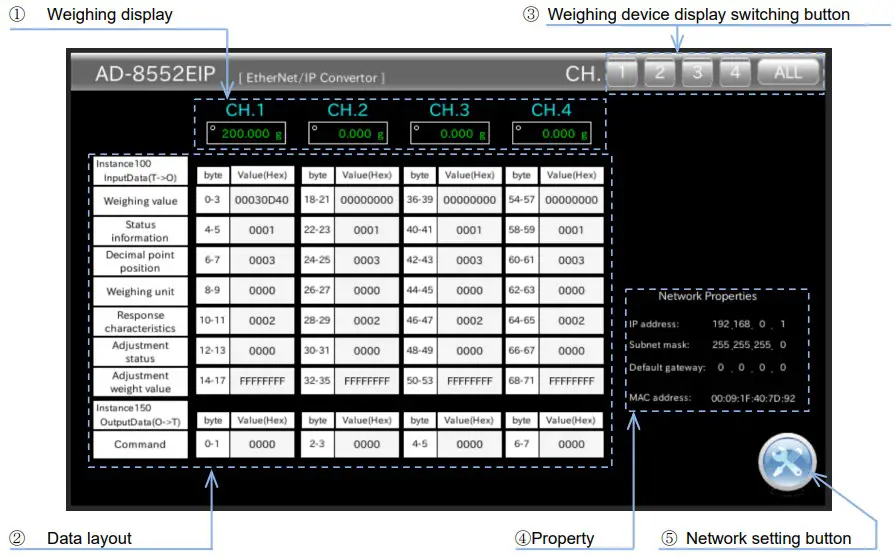
| No. | Name | Description |
| ① | Weighing display | Displays the “weighing value” of the weighing device connected to CH.1 to 4. |
| ② | Data layout | Displays the data layout of EtherNet/IP communication |
| ③ | Weighing device display switching button | The “10-3. Weighing device operation screen” connected to each channel is displayed. |
| ④ | Property | Displays the “Network Settings” and “MAC Address” of the AD-8552EIP. |
| ⑤ | Network setting button | The AD-8552EIP “10-4. Network Setting Screen” is displayed. |
10-3 Weighing Device Operation Screen
- The weighing device operation screen has a mode (CH1 to 4) that displays one channel on one screen and a mode (ALL) that displays four channels.
■ 1 channel display (CH1 to 4)
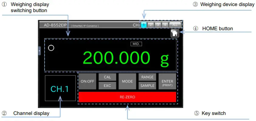
| No. | Name | Description |
| ① | Weighing display | Displays the “weighing value” of the weighing device connected to the channel display. |
| ② | Channel display | Displays channels |
| ③ | Weighing device display switching button | “10-3. Weighing Device Operation Screen” connected to each channel is displayed. |
| ④ | HOME button | “10-2. HOME display” is displayed. |
| ⑤ | Key switch | Operates the weighing device※1 |
※1.The key switches that can be operated differ depending on the measuring instrument to be connected. The contents are in table of “3-2. Compatible models” and each measuring instrument.
Please refer to the instruction manual.
■ 4 channel display (ALL) ※2
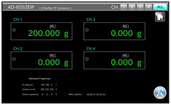
※2.”4 channel display (ALL)” only displays the weighing values of 4 weighing devices.
(When operating the weighing device from the WEB interface, use the channel to which the weighing device to be operated is connected. Please go from “1 channel display”.)
10-4 Network Setting Screen
- On the network setting screen, you can set the IP address, subnet mask, and default gateway.
Note
- Please consult with your network administrator before connecting to the network.
- Set the IP address so that it does not overlap with other devices.
■ Network setting screen
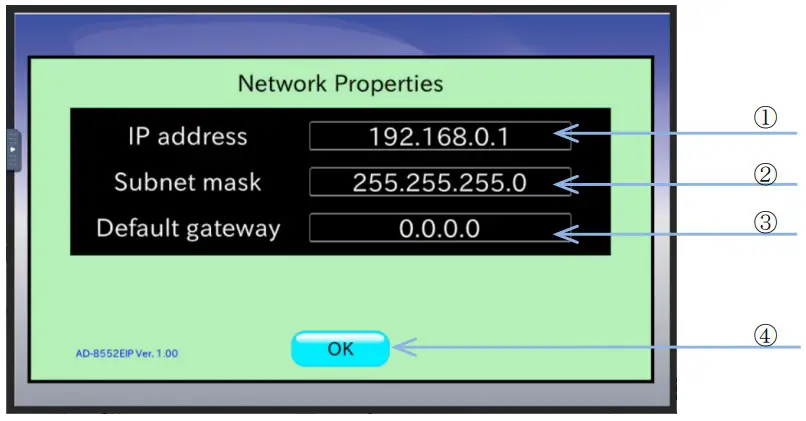
| Name | Setting value(setting range) | Description | |
| ① | IP address | 0.0.0.0 to 255.255.255.255 Please consult your network administrator for the setting values. | Displays the IP address of this device. |
| ② | Sub-net mask | Displays the subnet mask of this unit. | |
| ③ | Default gateway | Displays the default gateway of this device. | |
| ④ | OK button | ― | The display returns to “10-2. HOME display”. |
Troubleshooting
| Phenomenon | Confirmation and countermeasures |
| POWER LED does not illuminate | Make sure that power is properly supplied to the power supply terminal of the AD- 8552EIP. ・Is the voltage correct?(DC 24V) ・Is the cable connected correctly? |
| NS LED does not turn green | The connection with the scanner (PLC) has not been established. ・Is the IP address set so that it does not overlap? ・Is the signal output from the scanner? |
| NS LED is flashing | The connection with the scanner (PLC) has timed out. ・Is the Ether Net/IP communication cable broken? ・Is the scanner turned on? |
| IP address cannot be changed | Turn the power of the AD-8552EIP off and then on again. When the power is turned on, the changes made to the switch and WEB interface are read and reflected in the operation. |
| Non-weighing status flag is “1”. | Check the setting of the weighing device. ・Check the RS-232C communication settings of the corresponding channel. ・Is the output format of the weighing device set to the A&D standard format? |
| AD-8552EIP settings cannot be changed. | Turn the AD-8552EIP off and then on again. When the power is turned on, the switch status is read and reflected in the operation. |
© 2022 All rights reserved.
No part of this publication may be reproduced, transmitted, transcribed, or translated into any language in any form by any means without the written permission of A&D Company, Limited.
![]() A&D Company, Ltd.
A&D Company, Ltd.
A&D Company, Limited
3-23-14 Higashi-Ikebukuro, Toshima-ku, Tokyo 170-0013, JAPAN
Telephone: [81] (3) 5391-6132
Fax: [81] (3) 5391-1566
A&D ENGINEERING, INC.
47747 Warm Springs Blvd, Fremont, California 94539, U.S.A.
Tel: [1] (800) 726-3364 Weighing Support:[1] (888) 726-5931
Inspection Support:[1] (855) 332-8815
A&D INSTRUMENTS LIMITED
Unit 24/26 Blacklands Way, Abingdon Business Park, Abingdon, Oxfordshire OX14 1DY United Kingdom
Telephone: [44] (1235) 550420
Fax: [44] (1235) 550485
A&D AUSTRALASIA PTY LTD
32 Dew Street, Thebarton, South Australia 5031, AUSTRALIA
Telephone: [61] (8) 8301-8100
Fax: [61] (8) 8352-7409


