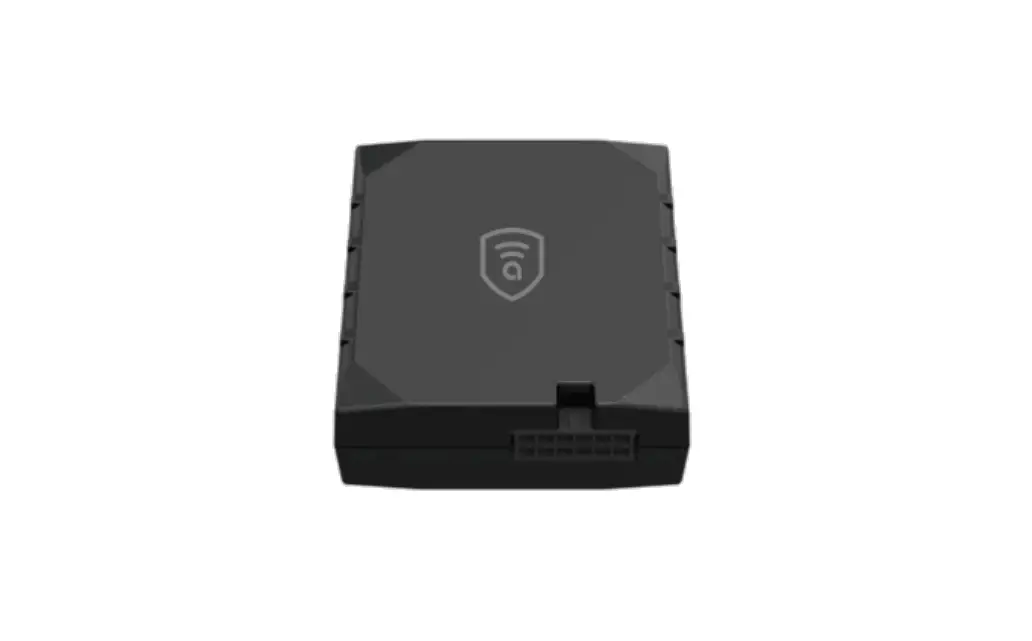
amber connect AGT400-la Professional LTE CAT M1-GNSS Terminal

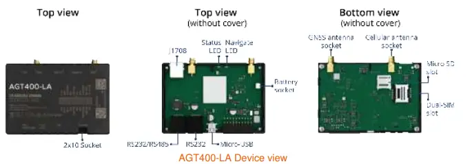
Know your device
Pinout
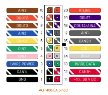
| Pin number | Pin name | Description |
| 1 | GND (-) | Ground |
| 2 | CAN 1L | SAE J1939 CAN interface Low channel 1 |
| 3 | 1WIRE POWER | Power supply pin for Dallas 1-Wire® devices |
| 4 | DIN4 | Digital input, channel 1 |
| 5 | DIN2 | Digital input, channel 2 |
| 6 | CAN 2L | SAE J1939 CAN interface Low channel 2 |
| 7 | AIN2 | Analog input, channel 2. Input range: 0-30V/0-10V DC |
| 8 | DOUT3 | Digital output. Open collector output |
| 9 | DOUT2 | Digital output. Open collector output |
| 10 | AIN3 | Analog input, channel 3. Input range: 0-30V/0-10V DC |
| 11 | VCC (+) | Power supply (+10-30 V DC) |
| 12 | CAN 1H | SAE J1939 CAN interface High channel 1 |
| 13 | 1WIRE DATA | Data channel for Dallas 1-Wire® devices |
| 14 | DIN3 | Digital input, channel 3 |
| 15 | IGN (DIN1) | Digital input, channel 1. DEDICATED FOR IGNITION INPUT |
| 16 | CAN 2H | SAE J1939 CAN interface High channel 2 |
| 17 | AIN1 | Analog input, channel 1. Input range: 0-30V/0-10V DC |
| 18 | DOUT4/AIN4 | Digital output. Open collector output OR Analog input, channel 4. Input range: 0-30V/0-10V DC |
| 19 | DOUT1 | Digital output. Open collector output |
| 20 | K-Line | K-LINE interface for online Tachograph Vehicle Data transfer |
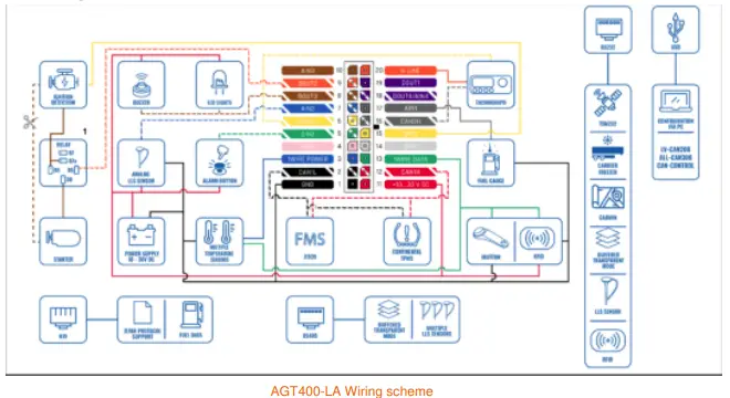
Wiring scheme
Set up your device
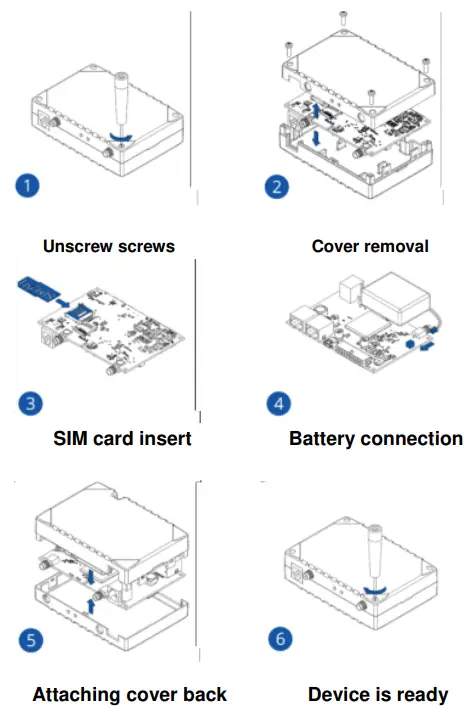
How to insert Micro-SIM card and connect the battery
- Unscrew 4 screws counter clockwise that are located on the bottom of the device.
- Remove the cover.
- Insert SIM card as shown with PIN request disabled or read Security info how to enter it later in Amber Configurator. Make sure that SIM card cut-off corner is pointing forward to slot. SIM slot 1 is closer to PCB, SIM slot 2 is the upper one.
- Connect battery as shown to device.
- After configuration, see “PC Connection (Windows)”, attach device cover back
- Screw in all screws. Device is ready to be mounted.
Mounting recommendations
Connecting wires
- Wires should be connected while the module is not plugged in.
- Wires should be fastened to the other wires or non-moving parts. Try to avoid heat emitting and moving objects near the wires.
- The connections should not be seen very clearly. If factory isolation was removed while connecting wires, it should be applied again.
- If the wires are placed in the exterior or in places where they can be damaged or exposed to heat, humidity, dirt, etc., additional isolation should be applied.
- Wires cannot be connected to the board computers or control units.
Connecting power source
- Be sure that after the car computer falls asleep, power is still available on chosen wire. Depending on car, this may happen in 5 to 30 minutes period.
- When the module is connected, measure the voltage again to make sure it did not decrease.
- It is recommended to connect to the main power cable in the fuse box.
- 3 A, 125 V external fuse
Connecting ignition wire
- Be sure to check if it is a real ignition wire power does not disappear while starting the engine.
- Check if this is not an ACC wire (when key is in the first position, most electronics of the vehicle are available).
- Check if power is still available when you turn off any of vehicles devices.
- Ignition is connected to the ignition relay output. As alternative, any other relay, which has power output when ignition is on, may be chosen.
• Connecting ground wire
- Ground wire is connected to the vehicle frame or metal parts that are fixed to the frame.
- If the wire is fixed with the bolt, the loop must be connected to the end of the wire.
- For better contact scrub paint from the spot where loop is going to be connected.
PAY ATTENTION! Connecting the power supply must be carried out in a very low impedance point of on-board vehicle network. Connecting the GND at an arbitrary point to the mass of the car is unacceptable, as static and dynamic potentials on the line GND will be unpredictable, which can lead to unstable AGT400-LA operation and even its failure.
LED indications
Navigation LED indications
| Behaviour | Meaning |
| Permanently switched on | GNSS signal is not received |
| Blinking every second | Normal mode, GNSS is working |
| Off | GNSS is turned off because: Device is not working or Device is in sleep mode |
| Blinking fast constantly | Device firmware is being flashed |
Status LED indications
| Behaviour | Meaning |
| Blinking every second | Normal mode |
| Blinking every two seconds | Sleep mode |
| Blinking fast for a short time | Modem activity |
| Off | Device is not working or Device is in boot mode |
Characteristics
Basic characteristics
| Module | |
| Name | AGT 400-LA |
| Technology | LTE Cat 1, UMTS, GSM |
| GNSS | |
| GNSS | GPS, GLONASS, GALILEO, BEIDOU, SBAS, QZSS, DGPS, AGPS |
| Receiver | 33/99 channel |
| Tracking sensitivity | -165 dBM |
| Accuracy | < 3 m |
| Hot start | < 1 s |
| Warm start | < 25 s |
| Cold start | < 35 s |
| Cellular | |
| Technology | LTE(CaT1)/3G(UMTS/HSPA)/2G(GSM/GPRS)/GNSS |
| 2G bands | EG91-EX: GSM: B3/B8EG91-AUX: GSM: B2/B3/B5/B8 |
| 3G bands | EG91-EX: WCDMA: B1/B8EG91-AUX: WCDMA: B1/B2/B5/B8 |
| 4G bands | EG91-EX: LTE FDD: B1/B3/B7/B8/B20/B28 |
| Data transfer | LTE: LTE FDD: Max 10Mbps (DL)/Max 5Mbps (UL) UMTS: WCDMA: Max 384Kbps (DL)/Max 384Kbps (UL) |
| Data support | SMS (text/data) |
| Power | |
| Input voltage range | 10-30 V DC with overvoltage protection |
| Back-up battery | 550 mAh 8,4V Ni-MH battery |
| Internal fuse | 3 A, 125 V |
| 2 W max. Current consumption at 12 V | GPRS: average 60 mA Nominal: average 45 mA GNSS sleep: average 32 mA Deep Sleep: average 4 mA Online Deep Sleep: average 11 mA |
| 2 W max. Current consumption at 24 V | GPRS: average 35 mA Nominal: average 24 mA GNSS sleep: average 17 mA Deep Sleep: average 2,9 mA Online Deep Sleep: average 7 mA |
| Interface | |
| Digital Inputs | 4 |
| Digital Outputs | 4 |
| Analog Inputs | 4 |
| 1-Wire temperature sensors | 6 |
| 1-Wire iButton | 1 |
| RS232 | 2 |
| RS485 | 1 |
| CAN J1939 | 2 |
| J1708 | 1 |
| K-Line | 1 |
| LVCAN/ALLCAN | 1 |
| GNSS antenna | External High Gain |
| GSM antenna | External High Gain |
| USB | 2.0 Mini-USB |
| LED indication | 2 status LED lights |
| SIM | Micro-SIM |
| SIM | 2x SIM Card (Dual-SIM) |
| Memory | 2MB internal flash memory and external SD card up to 32 GB. |
| Features | |
| Sensors | Accelerometer |
| Scenarios | Green Driving, Over Speeding detection, Jamming detection, Excessive Idling detection, Crash detection, Immobilizer, iButton Read Notification, Towing detection, |
| Functionalities | Crash detection, Auto Geofence, Manual Geofence, Trip Detection, Odometer, DDD download and Tacho Online Data |
| Sleep modes | GPS Sleep, Online Deep Sleep, Deep Sleep |
| Configuration and firmware update | FOTA Web, FOTA, Amber Configurator (USB) |
| SMS | Configuration, Events, DOUT control, Debug |
| GPRS commands | Configuration, DOUT control, |
| Time Synchronization | GPS, NITZ, NTP |
| Fuel monitoring | LLS (Analog), LV-CAN, ALL-CAN, CAN FMS, RS232/RS485 Fuel Sensor, Ultrasonic level sensor |
| Ignition detection | Digital Input , Accelerometer, External Power Voltage |
| Physical specification | |
| Dimensions | 104,1 x 76,8 x 31,5 mm (L x W x H) |
| Weight | 197 g |
| Operating environment | |
| Operating temperature (without battery) | -40 °C to +85 °C |
| Storage temperature (without battery) | -40 °C to +85 °C |
| Battery charge temperature | Ta = 20 ± 5 ℃ (Ambient Temp.) |
| Battery discharge temperature | Ta = 20 ± 5 ℃ (Ambient Temp.) |
| Battery storage temperature | -20 °C to +45° C |
| Ignition detection | Digital Input 1, Accelerometer, External Power Voltage, Engine |
| Operating humidity | 5% to 95% non-condensing |
| Ingress Protection Rating | IP41 |
Electrical characteristics
| Characteristic description | Value | |||
| Min. | Typ. | Max. | Unit | |
| Supply Voltage | ||||
| Supply Voltage (Recommended Operating Conditions) | +10 | +30 | V | |
| Digital Output (Open Drain grade) | ||||
| Drain current (Digital Output OFF) | 120 | μA | ||
| Drain current (Digital Output ON, Recommended Operating Conditions) | 0.5 | A | ||
| Static Drain-Source resistance (Digital Output ON) | 400 | 300 | mΩ | |
| Digital Input | ||||
| Input resistance (DIN1) | 15 | kΩ | ||
| Input resistance (DIN2) | 15 | kΩ | ||
| Input resistance (DIN3) | 15 | kΩ | ||
| Input resistance (DIN4) | 15 | |||
| Input voltage (Recommended Operating Conditions) | 0 | Supply voltage | V | |
| Input Voltage threshold (DIN1, DIN2, DIN3,DIN4) | 7.5 | V | ||
| Analog Input | ||||
| Input voltage (Recommended Operating Conditions), Range 1 | 0 | +10 | V | |
| Input resistance | 120 | kΩ | ||
| Input Voltage (Recommended Operating Conditions), Range 2 | 0 | +30 | V | |
| Input resistance | 147 | kΩ | ||
| 1-Wire | ||||
| Supply voltage | +3.3 | +3.9 | V | |
| Output inner resistance | 7 | Ω | ||
| Output current (Uout > 3.0 V) | 30 | mA | ||
| Short circuit current (Uout = 0) | 75 | mA | ||
| CAN Interface | ||||
| Internal terminal resistors CAN bus | 120 | Ω | ||
| Differential input resistance | 19 | 30 | 52 | kΩ |
| Recessive output voltage | 2 | 2.5 | 3 | V |
| Differential output voltage | 0.5 | 0.7 | 0.9 | V |
| Common mode input voltage | -30 | 30 | V | |
Safety information
This message contains information on how to operate AGT400-LA safely. By following these requirements and recommendations, you will avoid dangerous situations. You must read these instructions carefully and follow them strictly before operating the device!
- The device uses SELV limited power source. The nominal voltage is +12 V DC. The allowed voltage range is +10…+30 V DC.
- To avoid mechanical damage, it is advised to transport the device in an impact-proof package. Before usage, the device should be placed so that its LED indicators are visible. They show the status of device operation.
- When connecting the 2×10 connector wires to the vehicle, the appropriate jumpers of the vehicle power supply should be disconnected.
- Before dismounting the device from the vehicle, the 2×10 connector must be disconnected.
- The device is designed to be mounted in a zone of limited access, which is inaccessible to the operator. All related devices must meet the requirements of EN 62368-1 standard.
- The device AGT400-LA is not designed as a navigational device for boats.
- Do not disassemble the device. If the device is damaged, the power supply cables are not isolated or the isolation is damaged, DO NOT touch the device before unplugging the power supply.
- All wireless data transferring devices produce interference that may affect other devices which are placed nearby.
- The device must be connected only by qualified personnel.
- The device must be firmly fastened in a predefined location.
- The programming must be performed using a PC with autonomic power supply.
- Installation and/or handling during a lightning storm is prohibited.
- The device is susceptible to water and humidity.
Certification and Approvals
- AGT400-LA CE / RED
- AGT400-LA CE E-Mark
- AGT400-LA CE REACH
- AGT400-LA CE Declaration of IMEI assignment
- AGT400-LA CE Declaration of device operation temperature
This sign on the package means that it is necessary to read the User‘s Manual before your start using the device. Full User‘s Manual version can be found in our
Wiki.
This sign on the package means that all used electronic and electric equipment should not be mixed with general household waste.
Hereby, Amber declare under our sole responsibility that the above described product is in conformity with the relevant Community harmonization: European Directive 2014/53/EU (RED).
Warranty
Amber connect guarantees its products to be free of any manufacturing defects for a period of 24 months. With additional agreement we can agree on a different warranty period, for more detailed information please contact our sales manager.
All batteries carry a reduced 6 month warranty period.
If a product should fail within this specific warranty time, the product can be:
- Repaired
- Replaced with a new product
- Replaced with an equivalent repaired product fulfilling the same functionality
- Amber can also repair products that are out of warranty at an agreed cost.
Warranty Disclaimer
Amber products are intended to be used by persons with training and experience. Any other use renders the limited warranties expressed herein and all implied warranties null and void and same are hereby excluded. also excluded from this limited warranty are any and all incidental or consequential damages including but not limited to, loss of use or revenue, loss of time, inconvenience or any other economic loss.


