
Suntech ST4345GPS Enabled LTE CAT-M1 AVL Device

Introduction
This document describes features, protocols and detail operation of ST4345.
If there is another operation description document for special buyer to customize or model and the contents of the document is different with this, customizing document should be applied for special buyer.
Overview
Device consists of LTE-M1, GPS and event parts. The main purpose of device reports getting GPS position and other informs of vehicle to server periodically. Device can control or check connected lines and support additional functions.
Operation Mode
The device has 3 operation modes, driving, parking and emergency.
** Driving: Driving status when ignition is on.
** Parking: Parking status that starts if ignition is off during more than T1.
** Emergency: Once panic button is On or any other status as per designed.
The device sends emergency reports until A1 times or receiving server acknowledge.
Report
AVL reports GPS and some information at predefined interval, depending on the current modes. Also, AVL sends some alerts, for example, movement at the parking condition, changing of connected input line and so on.
Device distinguishes all reports with 6 types, Status report, emergency, event, alert, alive and command response.
Device can store reports when reporting route (For example, LTE-M1 condition) is not successful. Storage capacity is up to 2,000 status reports, 50 emergency reports, 50 alert reports (include event reports) and 1500 bytes as command response. In case of status reports, oldest report is erased and new report is buffered when the buffer is full and new status report enters (FIFO). When reporting condition is recovered, device starts sending all buffered reports. Also, this capacity can increase if it is needed.
Each type of reports has priority, and priority is as below.
Emergency ➔ Command Response ➔ Alert ➔ Status Report➔ Alive (Lowest)
Emergency is the first to be sent after recovering LTE-M1 condition.
Setting Parameter
Parameters of device can be changed by LTE-M1 or SMS, and some control can be realized also in the same way.
Detail protocols are described in Chapter 4.
Features
Key features are described here;
– Power Down
Device can process two steps of power-down, Sleep and Deep Sleep, for reducing power consumption when the vehicle is parked.
– LED Indicator
LED indicates LTE-M1 and GPS states. It’s helpful to check error cause.
– Events
Device has 2 output lines, 3 input lines and ignition line.
– Update Firmware by Over The Air (FOTA)
When Firmware of device has some error or has to be changed for a new service to be implemented, device can update internal ROM file by over the air (FOTA), remotely via LTE-M1. Customers do not need to visit every vehicle to download the new firmware. Method of FOTA describes at “SunTech_OTA_UA_Protocol” document in detail.
– Parking Lock
Device can check whether the vehicle moves off the preset parking boundary or starts driving without ignition on. In the case that it notes the unauthorized moving or driving, it sends emergency report immediately.
– Over speed
Device can check speed of vehicle and send alert of over-speed to server.
– GPS Antenna Checking
Device can alert when GPS antenna is disconnected. It’s applicable only for models that have external antenna.
– Main Power Checking
The device can recognize the main power and inform to server when main power line is disconnected or main power drops below preset value. It’s applicable only for battery model.
– Battery Error Alert
Device can alert about battery error related on charging. It’s applicable only for battery model.
Protocol Construction
All command and reports are string and follows below format.
Every filed is distinguished by semi colon.
All report string from device is ended by `r’ (0x0D).
Command message format (from server to device)
| HDR | DEV_ID | VER | Field 1 | Field 2 | … | Field n |
| Field | Definitions | Remark |
| HDR | String | “ST4345” + Command type |
| DEV_ID | 6 char. | Device ID of AVL |
| VER | “02” | Protocol Version. This is fixed with “02”. |
| Field 1 ~ n | String | Contents |
Device ID is unique number of each device that consists of 6digits.
If the command has invalid value or DEV_ID of the command that is sent by LTE-M1 or SMS is not matched with DEV_ID of the unit.
Report message format (from device to server)
| HDR | DEV_ID | SW_VER | Field 1 | Field 2 | … | Field n |
| Field | Definitions | Remark |
| HDR | String | “ST4345” + Report type |
| DEV_ID | 6 char. | Device ID of AVL |
| VER | “001” | Software version that the device has. |
| Field 1 ~ n | String | Contents |
Commands
When the device is received a command, it responds with response string and changes some parameters or acts related operation.
Network Parameters Setting
| HDR | DEV_ID | VER | AUTH | APN | USER_ID | USER_PWD | SEVER_IP | SEVER_PORT | ||||
| B_SEVER_IP | B_SEVER_IP | SMS_NO | PIN_NO | |||||||||
● Definition : Set network parameters and PIN number.
| Field | Definitions | Unit | Remark |
| HDR | “ST4345NTW” | Command type | |
| DEV_ID | 6 char. | Device ID | |
| VER | “02” | Protocol Version | |
| AUTH | ‘0’ /‘1’/’A’ | LTE-M1 authentication 0 : PAP(‘NO’ in Synctrack) | |
| APN | String | Access Point Name | |
| USER_ID | String | ID for LTE-M1 Access | |
| USER_PWD | String | Password for LTE-M1 Access | |
| SEVER_IP | String | Server IP Address | |
| SEVER_PORT | String | Server Port | |
| B_SEVER_IP | String | Backup Server IP Address | |
| B_SEVER_PORT | String | Backup Server Port | |
| SMS_NO | String | Phone number what the device sends SMS report to. This can be used for backup in the area that if LTE-M1 condition is not good. Or, it can be used main report method when IP and Port are empty.For no use, it should be empty. | |
| PIN_NO | String | PIN Number to release PIN lock if it is enabled | |
| <example> [command] ST4345NTW;850000;02;0;internet;;;111.111.111.111;8600;;;; [response] ST4345NTW;Res;850000;010;0;internet;;; 111.111.111.111;8600;;;; ST4345NTW;Res;850000;010;A1;tim.br;tim;tim; 111.111.111.111;8600;;;; <notes> ** If network does not require User ID and Password, these fields should be empty.Automatic LTE-M1 Set It the device is set to ‘Automatic LTE-M1 Set’, the device set LTE-M1 parameters automatically depending on inserted SIM. For example, if Airtel SIM is inserted, the device set AUTH to 0, APN to “aitelLTE-M1.com”, USER_ID and USER_PASS to empty. And the device reports response string after adding real LTE-M1 parameters when automatic LTE-M1 set is selected. | |||
Report Parameter Setting
● Definition : Set parameters related on report interval.
| Field | Definitions | Unit | Remark |
| HDR | “ST4345RPT” | Command type | |
| DEV_ID | 6 char. | Device ID | |
| VER | “02” | Protocol Version | |
| T1 | String | Sec | Interval for sending status report in parking mode Range : 0 ~ 86400 If 0, report in parking will be sent only one time when vehicle starts parking. |
| T2 | String | Sec | Interval for sending status report in driving mode Range : 0 ~ 60000 If 0, report in driving will be sent only one time when vehicle starts driving. |
| T3 | String | Sec | Interval for sending status report in emergency mode Range : 0 ~ 9999 If 0, emergency report will be sent only one time when emergency state occurs. |
| A1 | String | Number of attempts for emergency report until the device gets acknowledge from server If 0, no emergency report will be sent. | |
| SND_DIST | String | Meter | Distance interval for sending status report. Range : 0 ~ 60000 (60km) If 0, status report related on moving distance is disabled. If not 0, stats report is send when traveled distance reaches predefined SND_DIST. |
| T4 | String | Sec | Interval for sending keep alive string |
| SMS_T1 | String | Min | Interval for sending status report in parking mode |
| SMS_T2 | String | Min | Interval for sending status report in driving mode |
| SMS_PACK_NO | String | Report No in one SMS message | |
| ANGLE_RPT | String | Degree | Report STT message if it’s greater than ANGLE_RPT. 0 : Disable Range : 1 ~ 179 |
| RPT_TYPE | String | Set the type of reporting. 0: FIFO : First in First Out. 1: LIFO : Last In First Out. | |
| <example> [command] ST4345RPT;850000;02;180;120;60;3;0;0;0;0;0;0;0 [response] ST4345RPT;Res;850000;010;180;120;60;3;0;0;0;0;0;0;0 <notes> ** If report interval is set big number, network may disconnect LTE-M1 connection because LTE-M1 communication is not progressed for a long time. So, unit may not receive command by LTE-M1. T4 is for protecting against this disconnection by sending short data with short term. ** Alive report can be sent only when the device has no data to send during T4 interval. | |||
Event Parameter Setting
| HDR | DEV_ID | VER | IGNITION | T1 | T2 |
| IN1_TYPE | IN2_TYPE | IN3_TYPE | IN1_CHAT | IN2_CHAT | IN3_CHAT |
| OUT1_TYPE | OUT2_TYPE | OUT1_ACTIVE | OUT2_ACTIVE | ||
| PULSE1_NO | PULSE1_ON | PULSE1_OFF | PULSE2_NO | PULSE2_ON | PULSE2_OFF |
| IN4_TYPE | IN5_TYPE | IN4_CHAT | IN5_CHAT | BAUD | |
● Definition : Set parameter related event.
| Field | Definitions | Unit | Remark |
| HDR | “ST4345EVT” | Command type | |
| DEV_ID | 6 char. | Device ID | |
| VER | “02” | Protocol Version | |
| T1 | String | Sec | Delay for entering idle mode after ignition goes to off |
| T2 | String | Sec | Delay for entering active mode after ignition goes to on |
| IN1_TYPE | ‘0’ ~ ‘7’ | 0 = Falling Edge 1 = Rising Edge 2 = Both Edge (Falling & Rising) 3 = Panic Button 4 = Call1 Button 5 = Call 2 Button 6 = Reserved 7 = Anti-Theft Button 13 = Disable Immobilizer if it’s activated by jammer detector. Default = ‘3’.Only the device that included voice option (audio circuit) can be set to ‘Call1 Button’ or ‘Call2 Button’. | |
| IN1_CHAT | String | 100ms | Input1 chattering time. Range : 0 ~ 9999 Default = 3 sec. If 0, input1 is not checked. |
| OUT1_TYPE | ‘0’ ~ ‘5’ | 0 = GPIO 1 = immobilizer 2 = Immobilizer & Auto active Auto active means immobilizer is activated automatically when the vehicle starts parking. 3 = Pulse 4 = LED Out for indicating call status. Refer 7-2-3. 5 = Buzzer | |
| OUT1_ACTIVE | ‘0’ or ‘1’ | 0 = Open when out1 is active 1 = GND when out1 is active | |
| PULSE1_NO | String | Pulse number when out1 type set to pulse. Range : 0 ~ 9999 If pulse no is 9999, pulsing runs permanently. | |
| PULSE1_ON | String | 100ms | Active time of pulse1 Range : 0 ~ 9999 It should be set with even number. |
| PULSE1_OFF | String | 100ms | Inactive time of pulse1 Range : 0 ~ 9999 It should be set with even number. |
| BAUD | ‘0’ ~ ‘4’ | It’s available when extra events support RS232. Baud-rate 0 = No use 1 = 4800bps 2 = 9600bps 3 = 19200bps 4 = 38400bps 5 = 115200bps If the device does not support RS232, it should be 0. | |
| <example> [command] ST4345EVT;850000;02;1;60;0;3;2;2;30;20;20;1;0;1;0;0;0;0;0;0;0;0;0;0;0;0 [response] ST4345EVT;Res;850000;010;1;60;0;3;2;2;30;20;20;1;0;1;0;0;0;0;0;0;0;0;0;0;0;0 <notes> ** If IGNITION is set to ‘0’, device doesn’t check driving or parking state of the vehicle. It reports status string with idle mode always, and cannot support parking lock and the service that enters sleep or deep sleep automatically when the vehicle is parked. | |||
Type of no supported event line is fixed to “No Use”.
Below table is for example of 4 line event model.
| Field | Definitions | Unit | Remark |
| HDR | “ST4345EVT” | Command type | |
| DEV_ID | 6 char. | Device ID | |
| VER | “02” | Protocol Version | |
| IGNITION | ‘0’ ~ ‘2’ | Ignition using state 0 : Not use ignition 1 : Use ignition Line 2 : Virtual ignition(power) 3 : Virtual ignition (motion) | |
| T1 | String | Sec | Delay for entering idle mode after ignition goes to off |
| T2 | String | Sec | Delay for entering active mode after ignition goes to on |
| IN1_TYPE | ‘0’ ~ ‘5’ | 0 = Falling Edge 1 = Rising Edge 2 = Both Edge (Falling & Rising) 3 = Panic Button 4 = Call1 Button 5 = Call 2 Button 6 = Reserved 7 = Anti-Theft Button 13 = Disable Immobilizer if it’s activated by jammer detector. Default = ‘3’. Only the device that included voice option (audio circuit) can be set to ‘Call1 Button’ or ‘Call2 Button’. | |
| IN1_CHAT | String | 100ms | Input1 chattering time. Range : 0 ~ 9999 Default = 3 sec. If 0, input1 is not checked. |
| OUT1_TYPE | ‘7’ | 7 = No Use | |
| OUT1_ACTIVE | ‘0’ or ‘1’ | ||
| PULSE1_NO | ‘0’ | ||
| PULSE1_ON | ‘0’ | ||
| PULSE1_OFF | ‘0’ | ||
| BAUD | ‘0’ | 0 = No use | |
| <example> [command] ST4345EVT;850000;02;1;60;0;3;2;2;30;20;20;1;0;1;0;0;0;0;0;0;0;0;0;0;0;0 [response] ST4345EVT;Res;850000;010;1;60;0;3;8;8;30;0;0;6;6;1;0;0;0;0;0;0;0;8;8;0;0;0 <notes> ** In case of event 4 line model, IN2_TYPE, IN3_TYPE, IN4_TYPE, IN5_TYPE, OUT1_TYPE and OUT2_TYPE should be ‘No Use’. Type and chat time of non used event lines are set to ‘No Use’ and ‘0’ automatically although these filed of command is set to other value. | |||
LTE-M1 Parameter Setting
| HDR | DEV_ID | VER | SMS_LOCK | SMS_MT1 | SMS_MT2 | SMS_MT3 |
| SMS_MT4 | IN_CALL_LOCK | CALL_MT1 | CALL_MT2 | CALL_MT3 | CALL_MT4 | CALL_MT5 |
| CALL_MO1 | CALL_MO2 |
● Definition : Set parameters related SMS or Call.
| Field | Definitions | Unit | Remark |
| HDR | “ST4345LTE- M1” | Command type | |
| DEV_ID | 6 char. | Device ID | |
| VER | “02” | Protocol Version | |
| SMS_LOCK | ‘0’ or ‘1’ | Lock of Receiving Commands by SMS Disable (0) / Enable (1) If enabled, only commands that receives from SMS_MT1 ~ MT3 number can be accepted. | |
| SMS_MT1 | String | Up to 20 char. | Phone number for SMS commands |
| SMS_MT2 | String | Up to 20 char. | Phone number for SMS commands |
| SMS_MT3 | String | Up to 20 char. | Phone number for SMS commands |
| SMS_MT4 | String | Up to 20 char. | Phone number for SMS commands |
| IN_CALL_LOCK | ‘0’ or ‘1’ | Lock of Incoming Call Disable (0) / Enable (1) If enabled, only call from CALL_MT1 ~ MT5 number can be accepted. | |
| CALL_MT1 | String | Up to 20 char. | Phone number for call |
| CALL_MT2 | String | Up to 20 char. | Phone number for call |
| CALL_MT3 | String | Up to 20 char. | Phone number for call |
| CALL_MT4 | String | Up to 20 char. | Phone number for call |
| CALL_MT5 | String | Up to 20 char. | Phone number for call |
| CALL_MO1 | String | Up to 20 char. | Phone number for outgoing call from device |
| CALL_MO2 | String | Up to 20 char. | Phone number for outgoing call from device |
| <example> [command] ST4345LTE-M1;850000;02;0;;;;;0;;;;;;; [response] ST4345LTE-M1;Res;850000;010;0;;;;;0;;;;;;; <notes> ** When SMS or Call numbers are not set, that field should be empty. | |||
Service Parameter Setting
| HDR | DEV_ID | VER | PARKING_LOCK | SPEED_LIMIT | PWR_DN | CON_TYPE |
| ZIP | GROUP_SEND | MP_CHK | ANT_CHK | BAT_CHK | M_SENSOR | CALL |
| GEO_FENCE | DATA_LOG | ANTITHFT_CNT1 | ANTITHFT_CNT2 | JAM_DET | ||
| JAM_CHK_DIST | JAM_CHK_TM | |||||
● Definition : Set parameters related report.
| Field | Definitions | Unit | Remark | ||||
| HDR | “ST4345SVC” | Command type | |||||
| DEV_ID | 6 char. | Device ID | |||||
| VER | “02” | Protocol Version | |||||
| PARKING_LOCK | ‘0’ or ‘1’ | Parking lock enable (1) / disable (0) If 1, the device checks vehicle position in parking periodically. When the vehicle goes off some boundary or starts moving over some velocity, the device reports parking lock emergency. | |||||
| SPEED_LIMIT | String | Km/h | Over speed limit If 0, the device does not check over speed. If 1 and the vehicle runes over predefined value, device reports speed alerts once. | ||||
| PWR_DN | ‘0’ ~ ‘2’ | Power saving type 0 : Disabled sleep and deep sleep service 1 : Enabled deep sleep 2 : Enabled sleep | |||||
| CON_TYPE | ‘0’ ~ ‘2’ | Connection Type with Server 0 = KEEP_CON 1 = KEEP_DISCON 2 = KEEP_NOP Detail explanation is below. | |||||
| ZIP | ‘0’ or ‘1’ | Use Zip Disable (0) / Enable (1) | |||||
| GROUP_SEND | ‘0’ or ‘1’ | Group Send for stored data 0 : Disable 1 : Enable. One packet can include up to 5 reports. Group send is explained below. | |||||
| MP_CHK | ‘0’ or ‘1’ | Main Power Disconnection Check Disable (0) / Enable (1) | |||||
| ANT_CHK | ‘0’ or ‘1’ | GPS Antenna Connection Error Check Disable (0) / Enable (1) | |||||
| BAT_CHK | ‘0’ or ‘1’ | Backup Battery Error Check Disable (0) / Enable (1) | |||||
| M_SENSOR | ‘0’ ~’4’ | Motion Sensor | |||||
| Motion | Collision | Shock | |||||
| 0 | Disable | Disable | Disable | ||||
| 1 | Enable | Disable | Disable | ||||
| 2 | Disable | Disable | Enable | ||||
| 3 | Enable | Disable | Enable | ||||
| 4 | Disable | Enable | Disable | ||||
| 5 | Enable | Enable | Disable | ||||
| 6 | Disable | Enable | Enable | ||||
| 7 | Enable | Enable | Enable | ||||
| CALL | ‘0’ or ‘1’ | Support Call with headset Disable (0) / Enable (1) | |||||
| GEO_FENCE | ‘0’ or ‘1’ | Support Geo-fence Disable (0) / Enable (1) | |||||
| DAT_LOG | ‘0’ or ‘1’ | Log out with RS232 0 = No Use 1 = Enable getting saved log data by RS232 | |||||
| <example> [command] ST4345SVC;850000;02;1;120;0;0;0;0;1;1;1;0;0;0;0;0;0;0;0;0 [response] ST4345SVC;Res;850000;010;1;120;0;0;0;0;1;1;1;0;0;0;0;0;0;0;0;0 <notes> ** Function of M_SEMSOR can be used with the model that has motion sensor. If shock or collision detection is enabled, device will report to server when gets any shock or collision. ** If this parameter has been customized, This table should be disregarded and you should follow customized operation document. CON_TYPE 1. KEEP_CON : The device keeps TCP connection always and can receives a command by LTE-M1. 2. KEEP_DISCON : The device connects TCP connection when the data is sent. After sending, the device disconnects LTE-M1 and TCP connection if it estimates there is no data for sending within 3minutes. In this case, it cannot receive a command by LTE-M1. 3. KEEP_NOP : The device doesn’t send any report after be installed. When the device enters emergency mode or receive ‘Start Report’ command by SMS or RS232, it starts report depending on report parameters. It may be used for saving LTE-M1 fee. Current version cannot support this Group Send M_Sensor
Jamming detection procedure *Case of jamming LTE-M1 only. JAM_CHK_DIST : if 0, skip this function. If disable all of assist functions, just triggered by HAM_DET mode after detected jamming. | |||||||
Additional Parameters
| HDR | DEV_ID | VER | SVR_TYPE | B_SVR_TYPE | UDP_ACK | DEV_PORT |
● Definition : Setting additional parameter requested.
| Field | Definitions | Unit | Remark | |||||||||||||||||||||||||
| HDR | “ST4345ADP” | Command type | ||||||||||||||||||||||||||
| DEV_ID | 6 char. | Device ID | ||||||||||||||||||||||||||
| VER | “02” | Protocol Version | ||||||||||||||||||||||||||
| SVR_TYPE | ‘T’ / ‘U’ | Server Protocol Type T : TCP U : UDP | ||||||||||||||||||||||||||
| B_SVR_TYPE | ‘T’ / ‘U’ | Backup Server Protocol Type T : TCP U : UDP | ||||||||||||||||||||||||||
| UDP_ACK | ‘0’ ~ ‘3’ | ACK from Server when UPD is used. 0 : No use 1 : ACK when the server receives reports except alive. | ||||||||||||||||||||||||||
| DEV_PORT | String | Device’s port for receiving command from UDP server. It can be used only when UDP server is used. If ‘0’ or empty, the device would use port 9000. If not zero, the device can receive commands with port DEV_PORT. | ||||||||||||||||||||||||||
| Reserved | ‘0’ | |||||||||||||||||||||||||||
| Reserved | ‘0’ | |||||||||||||||||||||||||||
| Reserved | ‘0’ | |||||||||||||||||||||||||||
| Reserved | ‘0’ | |||||||||||||||||||||||||||
| Reserved | ‘0’ | |||||||||||||||||||||||||||
| Reserved | ‘0’ | |||||||||||||||||||||||||||
| <example> [command] ST4345ADP;850000;02;U;T;2;9000;0;0;0;0;0;0 [response] ST4345ADP;Res;850000;022;U;T;2;9000;0;0;0;0;0;0 <notes> This command can be applied from software version 22. ACK in case of UDP UDP is protocol that doesn’t check whether the data is transmitted successfully. So, the device checks completion of sending with ACK depending on UDP_ACK type. ACK is sent by server when the data is received. If the ACK is not sent during more than 2 minutes after sending, the device recognizes the data was not reached to server and sends the data again Examples of ACK report are as below.
| ||||||||||||||||||||||||||||
Set Parameters of Main Voltage
| HDR | DEV_ID | VER | CHR_STOP_THRES_12 | DECIDE_BAT_12 |
| OPERATION_STOP_THRES_12 | IGNDET_H | IGNDET_L | ||
● Definition : Set some value of main voltage.
| Field | Definitions | Remark |
| HDR | “ST4345MBV” | Command type |
| DEV_ID | 6 char. | Device ID |
| VER | “02” | Protocol Version |
| CHR_STOP_THRES_12 | String | Voltage value to stop backup battery charging in 12V vehicle. |
| DECIDE_BAT_12 | String | Voltage value to check whether the vehicle’s battery is 12V. |
| OPERATION_STOP_THRES_12 | String | Voltage value to protect vehicle battery. The device operation stops if car battery voltage is lower than this value in vehicle that has 12V power. |
| IGNDET_H | String | In case of virtual ignition, the vehicle can recognize driving state when vehicle power is more than IGNDET_H. Default = ‘0’ |
| IGNDET_L | String | In case of virtual ignition, the vehicle can recognize parking state when vehicle power is less than IGNDET_L. Default = ‘0’ |
| <example> [command] ST4345MBV;850000;02;10.5;22;19;8.00;18.00;0;0 [response] ST4345MBV;Res;850000;122;10.5;22;19;8.00;18.00;0;0 <note> IGNDET_H and IGNDET_L are ‘0’, device check parking and driving automatically. | ||
Set Parameters of Motion Sensor
| HDR | DEV_ID | VER | CHR_STOP_THRES_12 | DECIDE_BAT_12 | OPERATION_STOP_THRES_12 | ||
| IGNDET_H | IGNDET_L | VI_ON_THRES | VI_ON_DELAY | ||||
| VI_ON_PERCENT | VI_OFF_THRES | VI_OFF_DELAY | VI_OFF_PERCENT | ||||
● Definition : Set motion sensor parameter
| Field | Definitions | Unit | Remark |
| HDR | “ST4345MSR” | Command type | |
| DEV_ID | 6 char. | Device ID | |
| VER | “02” | Protocol Version | |
| SHOCK_DELAY | String | Sec. | Delay for entering shock detection mode after ignition off 0 – Disable Range : 1 ~ 21600 (5hour) Recommend : 600 ( 10 min.) |
| MOTION_THRES | String | Step | Detection level of shock violation. Range : 0.04 ~ 2.0 Recommend : 0.04 |
| SHOCK_THRES | String | Step | Detection level of shock violation. Range : 0.04 ~ 2.0 Recommend : 0.04 |
| COLL_THRES | String | Step | Gravity for collision report. Range : 0.1 ~ 2.0 |
| VI_ON_THRES | String | 1/255G | Threshold value for Motion Virtual Ignition On Range : 3~50 Default : 5 |
| VI_ON_DELAY | String | Sec. | Delay time for Motion Virtual Ignition On Range : 3~999 Default : 10 |
| VI_ON_PERCENT | String | % | Percent for Motion Virtual Ignition On. Range : 30~100 Default: 70 |
| VI_OFF_THRES | String | 1/255G | Threshold value for Motion Virtual Ignition Off Range : 3~50 Default : 5 |
| VI_OFF_DELAY | String | Sec. | Delay time for Motion Virtual Ignition Off Range : 3~999 Default : 10 |
| VI_OFF_PERCENT | String | % | Percent for Motion virtual Ignition Off. Range : 30 ~ 100 Default : 70 |
| <example> [command] ST4345MSR;;02;600;0.04;0.04;0.7;5;10;70;5;10;70 [response] ST4345MSR;Res;852588;128;600;0.04;0.04;0.70;5;10;70;5;10;70 <notes> * For the shock level, we recommend it to set to 0.04. if it’s over than 0.04, the sensor will be more insensitive as it for shock detection. | |||
Control Command
| HDR | DEV_ID | VER | CMD_ID |
● Definition : Controls some functions.
| Field | Definitions | Unit | Remark |
| HDR | “ST4345CMD” | Command type | |
| DEV_ID | 6 char. | Device ID | |
| VER | ‘01’ | Protocol Version | |
| CMD_ID | String | Control command content |
Caution : If it’s not correct the Unit ID, ignored.
Status Request
● Definition : Location poll, request of the status report.
| Field | Definitions | Unit | Remark |
| CMD_ID | “StatusReq” | Status request If received, the device sends status string instantly. | |
| <example> <example> [command] ST4345CMD;850000;02;StatusReq [response] ST4345STT;850000;010;20090724;07:12:16;00129;+37.479995;+126.885815;000.029;000.00; 7;1;0;15.33;100000;2;0002 | |||
Reset
● Definition : Reset all of parameters.
| Field | Definitions | Unit | Remark |
| CMD_ID | “Reset” | Reset Initialize all parameters with factory value and reboot the device. | |
| <example> [command] ST4345CMD;850000;02;Reset [response] ST4345CMD;Res;850000;010;Reset | |||
Preset
● Definition : Reset all of parameters.
| Field | Definitions | Unit | Remark | ||||
| CMD_ID | “Preset” | Report parameter setting values and current device status. Response includes network, report, event, LTE-M1 and service parameters. It includes status of device, also. | |||||
| <example> [command] ST4345CMD;850000;02;Preset [response] ST4345CMD;Res;850000;010;Preset; NTW;0;internet;;;111.111.111.111;8600;;;;1234; RPT;60;180;120;60;3;0;0;;;; EVT;1;60;0;3;2;2;30;20;20;1;1;1;0;0;0;0;0;0;0;0;0;0;0;0; LTE-M1;0;;;;;0;;;;;;;; SVC;1;120;0;0;0;0;1;1;1;0;0;0;0 DEV;0;0;0;0 [response] event 4 line model NTW;0;internet;;;111.111.111.111;8600;;;;1234; RPT;60;180;120;60;3;0;0;;;; EVT;1;60;0;3;8;8;30;0;0;6;6;1;0;0;0;0;0;0;0;0;0;0;0;0; LTE-M1;0;;;;;0;;;;;;;; SVC;1;120;0;0;0;0;1;1;1;0;0;0;0 DEV;0;0;0;0 <notes> ** After power on, device sends response string of preset once. ** DEV filed informs current status of device as below.
| |||||||
| Field | Definitions | Unit | Remark | ||||||||
| CMD_ID | “PresetA” | Report all parameters including additional parameter. | |||||||||
| <example> [command] ST4345CMD;850000;02;PresetA [response] ST4345CMD;Res;850000;010;PresetA; NTW;0;internet;;;111.111.111.111;8600;;;;1234; RPT;60;180;120;60;3;0;0;;;; EVT;1;60;0;3;2;2;30;20;20;1;1;1;0;0;0;0;0;0;0;0;0;0;0;0; LTE-M1;0;;;;;0;;;;;;;; SVC;1;120;0;0;0;0;1;1;1;0;0;0;0; ADP;U;T;2;9000;0;0;0;0;0;0; DEV;0;0;0;0;0;0;0;0 ** This command can be applied from software version 22. ** DEV filed informs current status of device as below
| |||||||||||
ACK of Emergency
● Definition : Stop emergency report.
| Field | Definitions | Unit | Remark |
| CMD_ID | “AckEmerg” | Acknowledgement of emergency report. The device will stop emergency reports if it is in emergency state. | |
| <example> [command] ST4345CMD;850000;02;AckEmerg [response] ST4345CMD;Res;850000;010;AckEmerg | |||
Enable1
● Definition : Active Output1.
| Field | Definitions | Unit | Remark |
| CMD_ID | “AckEmerg” | Acknowledgement of emergency report. The device will stop emergency reports if it is in emergency state. | |
| <example> [command] ST4345CMD;850000;02;AckEmerg [response] ST4345CMD;Res;850000;010;AckEmerg | |||
Disable1
● Definition : Inactive Output1.
| Field | Definitions | Unit | Remark |
| CMD_ID | “AckEmerg” | Acknowledgement of emergency report. The device will stop emergency reports if it is in emergency state. | |
| <example> [command] ST4345CMD;850000;02;AckEmerg [response] ST4345CMD;Res;850000;010;AckEmerg | |||
Request IMSI
● Definition : Inactive Output1.
| Field | Definitions | Unit | Remark |
| CMD_ID | “ReqIMSI” | Request IMSI (unique SIM ID) If received, device sends IMSI of using SIM. | |
| <example> [command] ST4345CMD;850000;02;ReqIMSI [response] ST4345CMD;Res;850000;010;ReqIMSI;724031111553779 | |||
Request ICCID
● Definition : Request the ICCID.
| Field | Definitions | Unit | Remark |
| CMD_ID | “ReqICCID” | Request ICCID (sequence number that is displayed on SIM) If received, device sends ICCID of using SIM. | |
| <example> [command] ST4345CMD;850000;02;ReqICCID [response] ST4345CMD;Res;850000;010;ReqICCID;89550230000084256668 | |||
ReqVer
● Definition : Request software version.
| Field | Definitions | Unit | Remark |
| CMD_ID | “ReqVer” | Request device version Device reports Model, Buyer, Protocol and S/W release version. | |
| <example> [command] ST4345CMD;850000;02;ReqVer [response] ST4345CMD;Res;850000;010;ReqVer;ST4345E_SAMPLE_STBASE_001 | |||
Erase All
● Definition : Erase all of data in buffer.
| Field | Definitions | Unit | Remark |
| CMD_ID | “EraseAll” | Erase saved all reports and disable outputs. This is needed to initialize just before device is delivered to a customer. | |
| <example> [command] ST4345CMD;850000;02;EraseAll | |||
Initialize Traveled Distance
● Definition : Initialize the travel distance.
| Field | Definitions | Unit | Remark |
| CMD_ID | “InitDist” | Set traveled distance to 0. | |
| <example> [command] ST4345CMD;850000;02;InitDist [response] ST4345CMD;Res;850000;010;InitDist | |||
Initialize Message Number
● Definition : Initialize the message sequence number.
| Field | Definitions | Unit | Remark |
| CMD_ID | “InitMsgNo” | Set message number to 0. | |
| <example> [command] ST4345CMD;850000;02;InitMsgNo [response] ST4345CMD;Res;850000;010;InitMsgNo | |||
Reboot
● Definition : reboot unit.
| Field | Definitions | Unit | Remark |
| CMD_ID | “Reboot” | Reboot device. | |
| <example> [command] ST4345CMD;850000;02;Reboot [response] ST4345CMD;Res;850000;010;Reboot | |||
Request SIM IP Address
● Definition : Request of the local IP address in SIM card.
| Field | Definitions | Unit | Remark |
| CMD_ID | “ReqSIMIP” | SIM card IP request | |
| <example> [command] ST4345CMD;850000;02;ReqSIMIP [response] ST4345CMD;Res;850000;010;ReqSIMIP;172.16.18.6 | |||
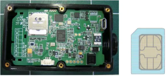
Installation
Insert SIM card
Backup battery
– The backup battery should be used when main power is cut off
Install
– The Device is fixed to the vehicle.
Assemble as below

Event Cable Color pin Description
Red: VCC (12V)
Black: Ground
Trouble Shooting (LED Indicator)
Blue LED: Indicates LTE-M1 status.
| LTE-M1 | Blink Count | Remarks |
| Normal | 1 | |
| Server Com. Error | 2 | <Possible Cause>
|
| LTE-M1 Com. Error | 3 | <Possible Cause>
|
| No Network | 4 | <Possible Cause>
|
| SIM PIN Locked | 5 | <Possible Cause>
|
| Cannot Attach NW | 6 | <Possible Cause>
|
| No SIM | 7 | <Possible Cause>
|
RED LED: Indicates GPS status.
| GPS | Blink Count | Remarks |
| Normal | 1 | |
| No Fix | 2 | <Possible Cause>
|
| GPS Chipset Error GPS Antenna Error | 4 | <Possible Cause>
|
Safety information
*. Caution.1 :
- High or low extreme temperature that a battery can be subjected to during use, storage or transportation
- Low air pressure at high altitude
- Disposal of a battery into fire or a hot oven, or mechanically crushing or cutting of a battery, that can result in an explosion.
- Leaving a battery in an extremely high temperature surrounding environment that can result in an explosion or the leakage of flammable liquid or gas.
- A battery subjected to extremely low air pressure that may result in an explosion or the leakage of flammable liquid or gas.
*. Caution.2 : Don’t use USB Connect. USB Connect is only use for production.
FCC Part 15.19
This device complies with part 15 of the FCC Rules. Operation is subject to the following two conditions:
(1) This device may not cause harmful interference, and (2) this device must accept any interference received, including interference that may cause undesired operation.
FCC Part 15.21
Any changes or modifications (including the antennas) to this device that are not expressly approved by the manufacturer may void the user’s authority to operate the equipment.
FCC Part 15.105 Note :
This equipment has been tested and found to comply with the limits for a Class B digital device, pursuant to part 15 of the FCC Rules. These limits are designed to provide reasonable protection against harmful interference in a residential installation This equipment generates, uses and can radiate radio frequency energy and, if not installed and used in accordance with the instructions, may cause harmful interference to radio communications, However, there is no guarantee that interference will not occur in a particular installation. If this equipment does cause harmful interference to radio or television reception, which can be determined by turning the equipment off and on, the user is encouraged to try to correct the interference by one or more of the following measures:
- Reorient or relocate the receiving antenna.
- Increase the separation between the equipment and receiver.
- Connect the equipment into an outlet on a circuit different from that to which the receiver is connected.
- Consult the dealer or an experienced radio/TV technician for help.
Modifications not expressly approved by the manufacturer could void your authority to operate the equipment under FCC rules.
Suntech International Ltd.


