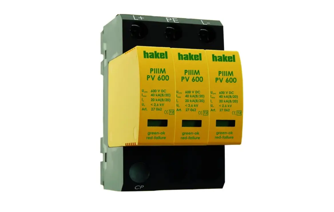
hakel PIIIM PV 200-2 V Series Surge Arrester for Photovoltaics Instruction Manual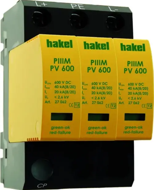
Instruction
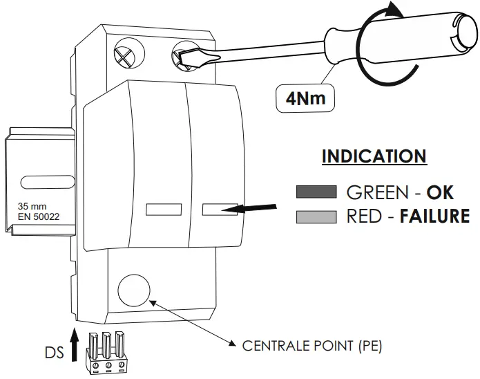
CENTRAL POINT: FOR MEASURING
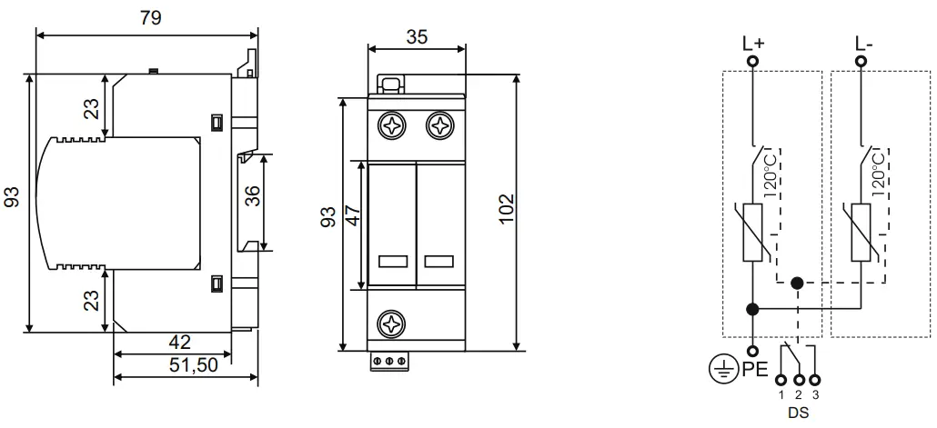
TECHNICAL DATA
| Type PIIIM PV 200/2 PIIIM PV 200 DS/2 Vseries | ||
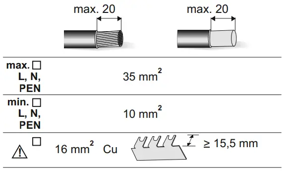
| Max. continuous operating voltage (L+,L-)Max. continuous operating voltage (L,PE) | UCPV | 200 V DC100 V DC |
| Open circuit voltage of PV generator (L+,L-) | UOCSTC | UOCSTC < UCPV/1,2 = 167 V |
| Short circuit withstand | ISCWPV | 25 A |
| Max. discharge current (8/20) | Imax | 40 kA |
| Nominal discharge current (8/20)Application | In | 15 kAL+/L-, L+/PE, L-/PE |
| Voltage protection level at In (L+/L-)Voltage protection level at In (L+/PE) | UP | < 800 V< 400 V |
| Response time | tA | < 25 ns |
| Weight | m | 180 g |
| Lifetime | min.100 000 h | |
| Article number | ||
| PIIIM PV 200/2PIIIM PV 200 DS/2 | 27 063 | |
| 27 064 | ||
TEST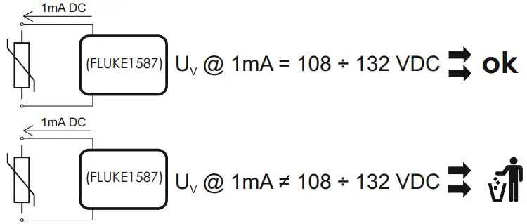
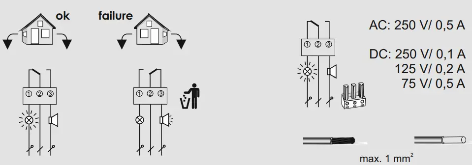
REMOTE MONITORING
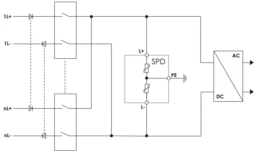
RECOMMENDED CONNECTION
NOTE: For the PV inverters, acceptable overvoltage is linked to maximum open circuit voltage and to technological choice of the manufacturer. If no other information is given, the overvoltage withstanding can be estimated to 5x U . 0CSTC
Safety Instruction
The device may only be connected and installed by an electrically skilled staff. National standards and safety regulations must be abided The device must be checked for external damage prior to installation. If any damage or other defects are found, the device must not be installed. Its use is only permitted within the limits stated in these installation instructions. If the device is overloaded above the given values, it can be destroyed a n d a l s o o t h e r e q u i p m e n t connected to the device can be damaged. Opening or otherwise tampering with the device invalidates the warranty.