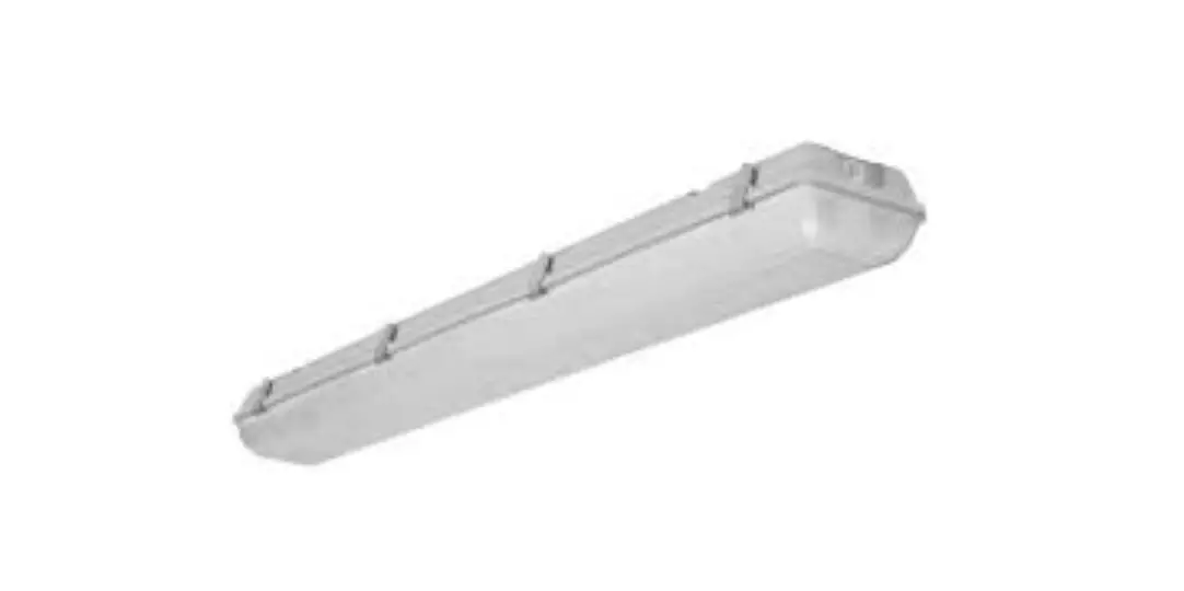
NaturaLED 9281 LED Vapor Tight Installation Guide
![]() WARNING
WARNING
To reduce the risk of electrical shock, fire, or injury to persons; read and follow all warnings and installation instructions before installing. All installation should be performed by a qualified electrician.
Risk of Electric Shock
Ensure power is off before installation or inspection. All wirings are performed in accordance with Electrical Code and local electrical code.
Risk of Fire
Fixtures are rated for use in 120-277V or 120-347V,50-60Hz protected circuit and 90 C rated supply wire.
FOR YOUR SAFETY
While performing installations described, gloves, safety glasses or goggles should be worn.
Install this kit only in the luminaire that have the construction features and dimensions shown in the photographs and/or drawings. Do not make or alter any open holes in an enclosure of wiring or electrical components during kit installation.
To prevent wiring damage or abrasion, do not expose wiring to edges of sheet metal or other sharp objects. Do not alter, relocate, or remove wiring, lamp holders, power supply, or any other electrical component.
SUITABLE FOR WET LOCATIONS.
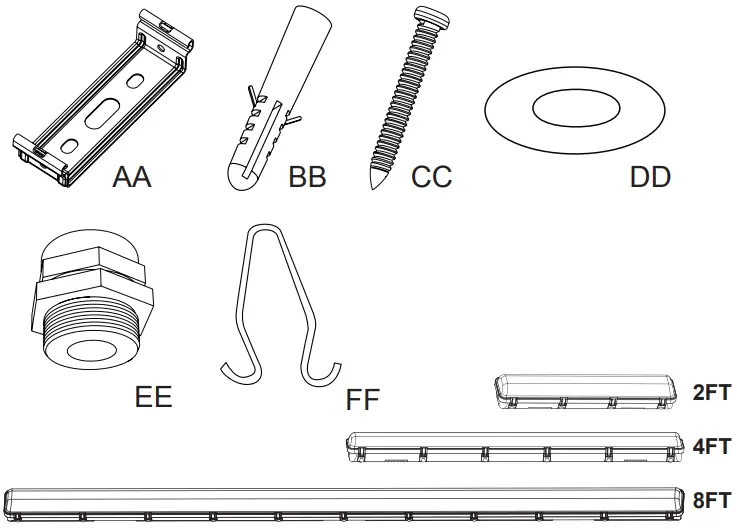
INSIDE THE BOX
| PART | DESCRIPTION | 2FT QTY | 4FT QTY | 8FT QTY |
| AA | BRACKET | 2 | 2 | 3 |
| BB | ANCHOR | 4 | 4 | 6 |
| CC | M4*40 SCREW | 4 | 4 | 6 |
| DD | WASHER | 4 | 4 | 6 |
| EE | WATERPROOF JOINT | 1 | 1 | 1 |
| FF | TRIANGLE SHAPE HOOK | 2 | 2 | 3 |
Plustrie USA
2000 S. Grove Ave, Blodg B
Ontario CA 91761
www.baturalED.com
T: 909-930-6868
T: 888-758-7443
F: 909-930-9988
Made In China
INSTALLATION INSTRUCTION
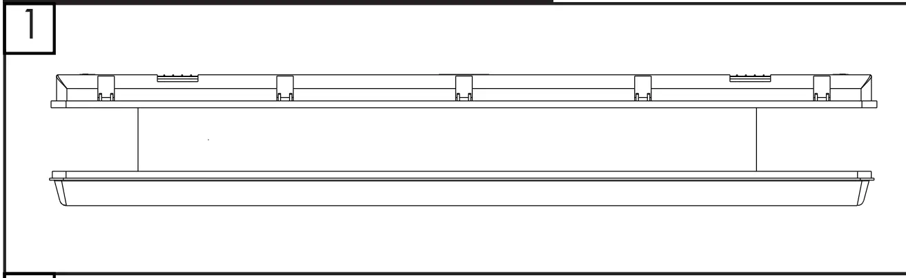
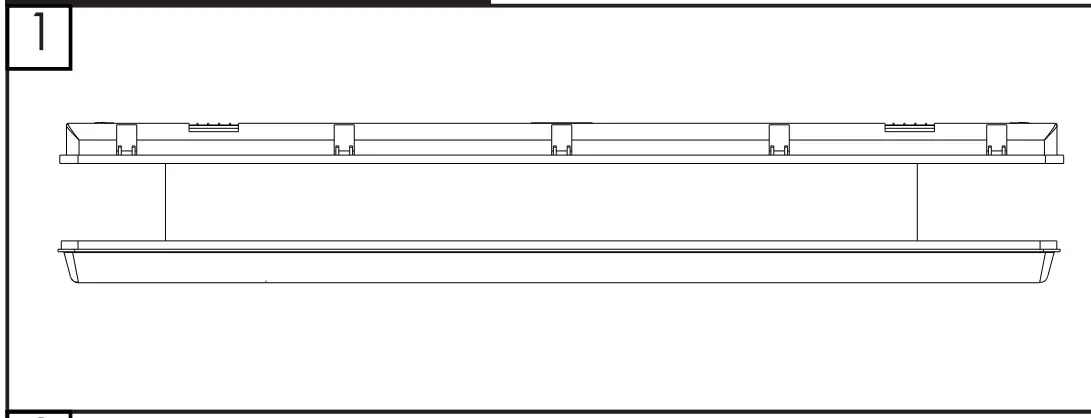
Disconnect the power before installation. Exploded view of completed assembly with component call out. 1,2,3, etc.
Celling / Wall Installation
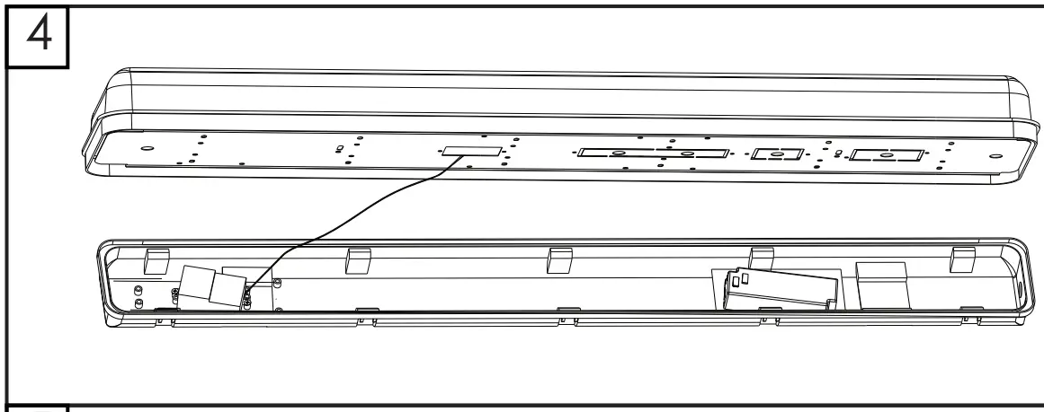
- Turn off the power, open the housing.

- Open the fixture and loosen the end waterproof joint nut.

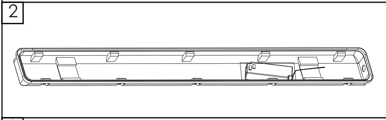
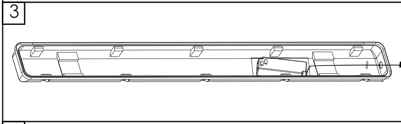
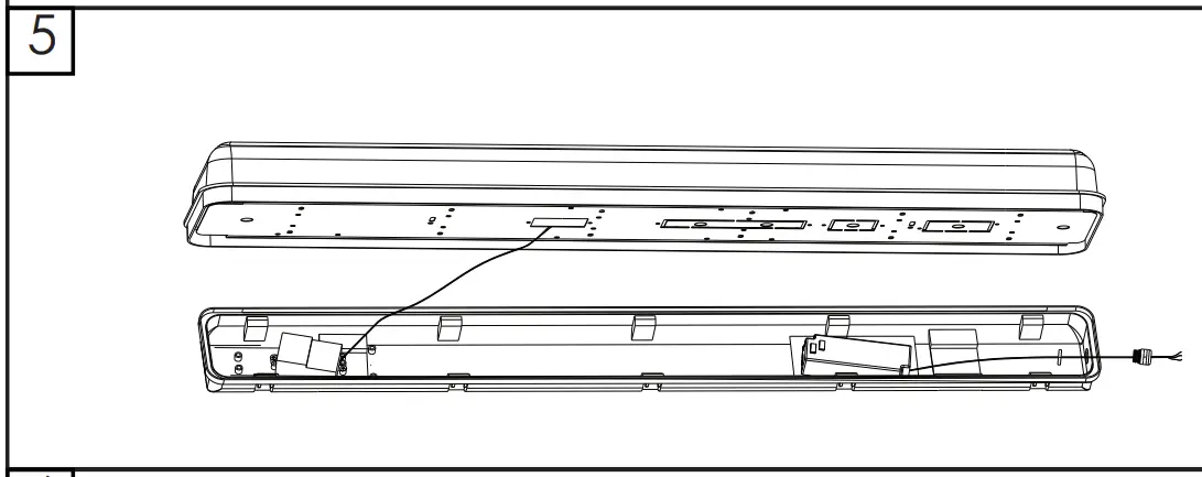
- Pass the cable wire through the waterproof joint hole and tighten the nut.
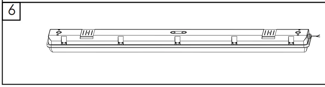
- Close the fixture
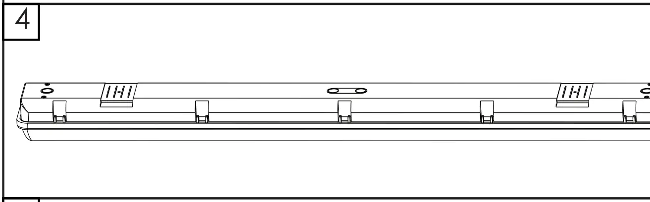
- Locate 4 drill holes for mounting brackets, see left drawing for measurements.

Use hardware found in hardware kit. - Attach brackets to the ceiling with M4*40 screws.

- Attach housing to the brackets.
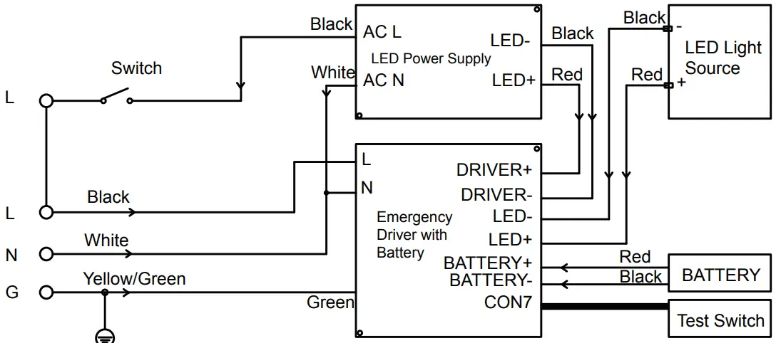
- Connect power to driver. Follow below wiring diagram and make sure the power supply is disconnected before connecting.

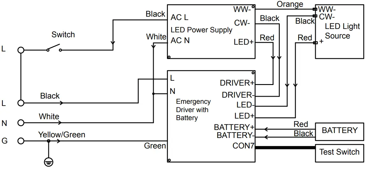
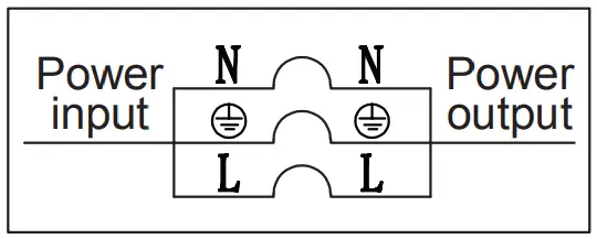
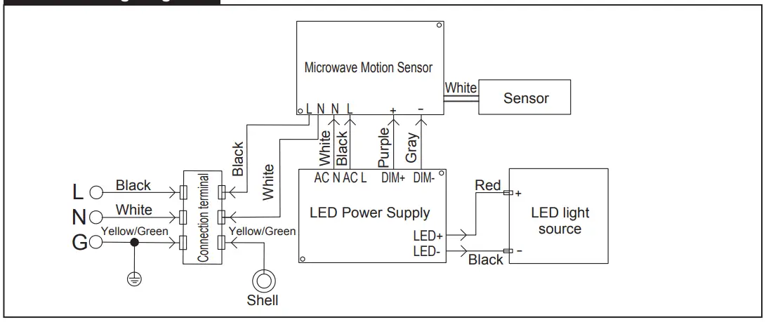
Wiring Diagram
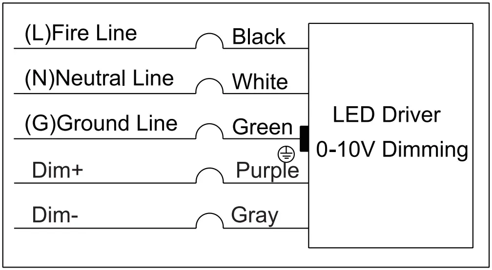
- Connect the lamp sheath wire with the external power supply wire, and connect it according to the diagram.

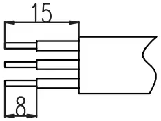
- The length of the sheath stripping is suggested as shown on the upper right.

Warning:
Note that L is a brown conductor, N is a blue conductor, and the ground is a yellow conductor. Power supply should not be connected first during operation.
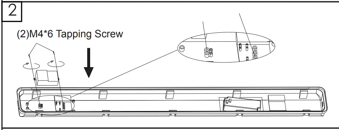
Sensor Installation
- Turn off the power, open the housing.

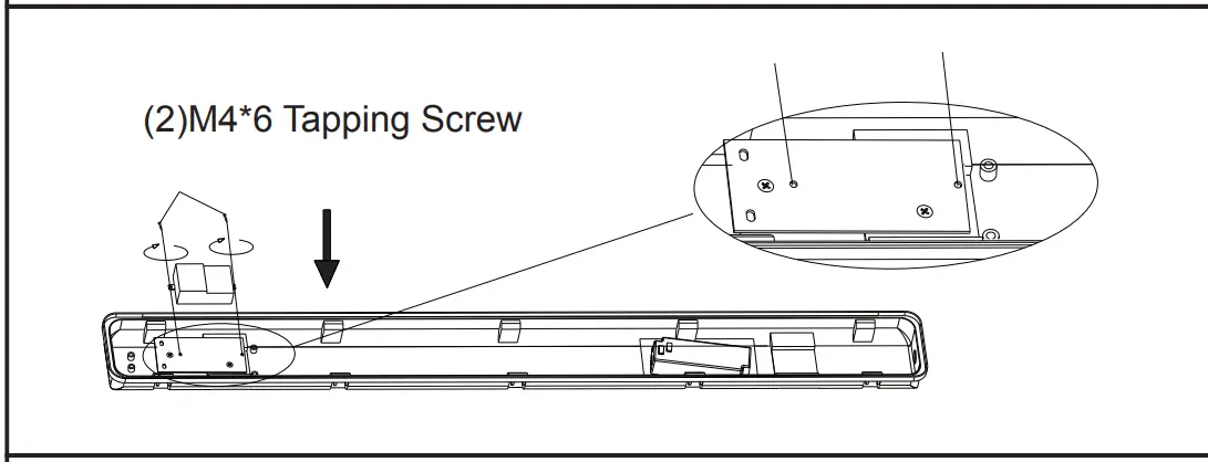
- Lock sensor with M4*6 tapping screw.
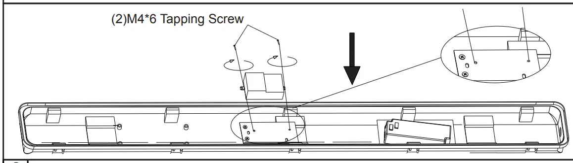
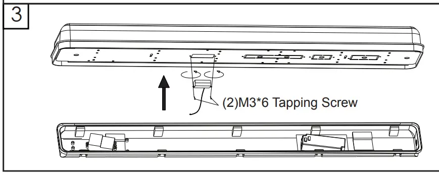
Put the sensor fixed plate on the housing with M4*6 tapping screw and lock sensor with M3*6 screw.
Same operation as 2FT
- Fix the sensor probe on the reflector plate.

- Connect Inductor wire.

- Pass the cable through the waterproof joint hole and tighten the nut.

- Close the fixture.

Sensor Wiring Diagram
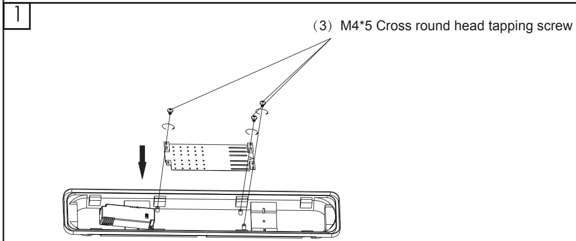
EM Driver Installation
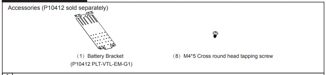
- Install the battery bracket in the bottom shell with (3) M4*5 screws.
Please put the “A” side up. (You can find the letter “A” on bracket)
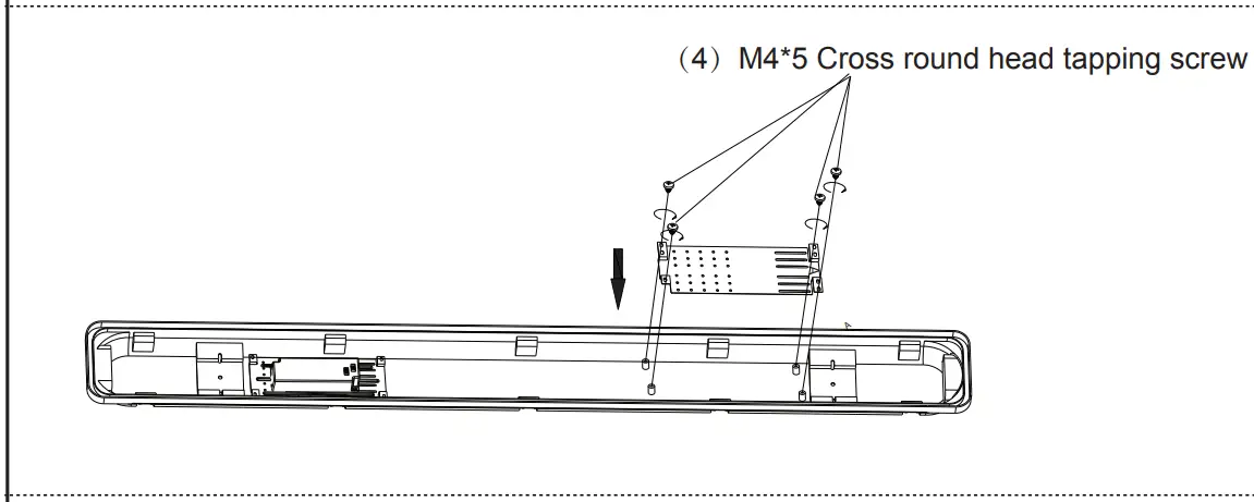
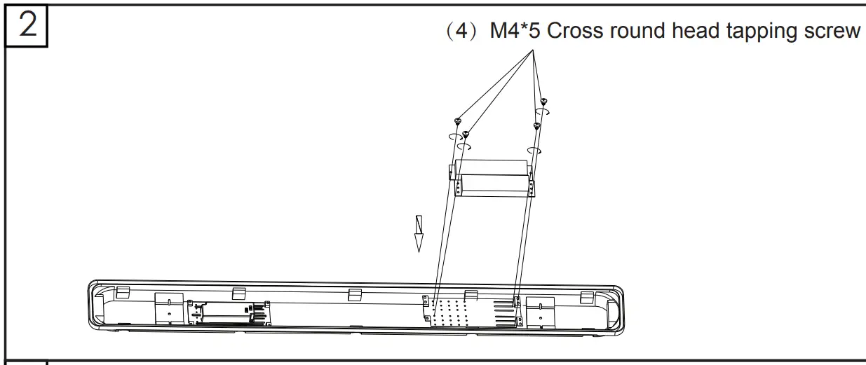
Install the battery bracket in the bottom shell with (4) M4*5 screws.
Please put the “A” side up. (You can find the letter “A” on bracket).
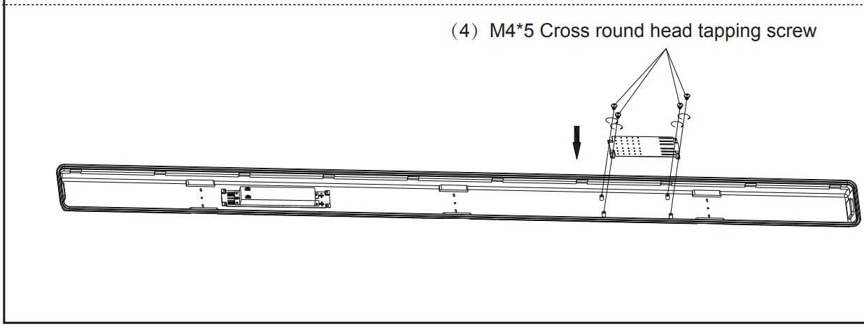
Install the battery bracket in the bottom shell with (4) M4*5 screws
- Fix the EM driver on the battery bracket with (4) M4*5 screws.


Wire Diagram for single CCT
Wire Diagram for 3CCT