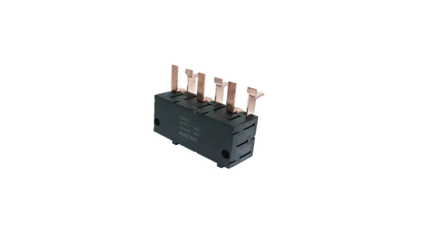
GOLDEN ZС90С Big High Power Latching Relay

Product Information
- Product Name: Z90
- Product Type: Big high-power latching relay
- Characteristics:
- Double-layer structure
- Stronger resistance to strong magnetism
- Complies with UC3 terms of IEC 62055-31
- Electrical life: 10000 times
- Outline dimensions: 98mm*40mm*38mm
- Contact Parameter:
- Contact Form: 3A, 3B
- Contact Resistance: Initial value
- Contact Material: AgSnO2
- Rated Loading: 120A
- Maximum Switching Voltage: Initial value
- Maximum Switching Current: Initial value
- Rated Switching Power: Initial value
- Mechanical Life: Initial value
- Coil Parameter:
- Rated Coil Power:
- Single Coil: about 5W
- Double Coil: about 10W
- Coil Specification Sheet:
- Single Coil:
- Rated Voltage: Initial value
- Operate and Release Pulse Width: Initial value
- Coil Resistance: Initial value
- Double Coil:
- Rated Voltage: 115, 460
- Operate and Release Pulse Width: Initial value
- Coil Resistance: 2.5+2.5, 3.6+3.6, 8.1+8.1, 14.4+14.4, 57.5+57.5, 230+230
- Single Coil:
- Rated Coil Power:
- Performance Parameter:
- Insulation Resistance: Initial value
- Voltage Between Coil and Contact Withstand: Initial value
- Voltage Between Open Contacts: Initial value
- Creepage Distance: Initial value
- Operating Time: Initial value
- Recovering Time: Initial value
- Impingement Stability Intensity: Initial value
- Vibration Double Amplitude: Initial value
- Humidity: Initial value
- Ambient Temperature: Initial value
- Coil Connection: PCB Fast Connection
- Terminal Pin Form Load Connection: PCB Fast Connection
- Weight: About
- Sealing Type: Dust-proof Type
- Certified Enterprises: 1/3
- Order Mark: ZC90C-3B-12-Q-V
Product Usage Instructions
- Before using the Z90 latching relay, read the user manual/instructions carefully.
- Ensure that the product is installed and used correctly to avoid any damage or accidents.
- Choose the appropriate coil type based on your requirements (single coil or double coil) and ensure that the rated voltage, operate and release pulse width, and coil resistance are set according to the initial values provided in the user manual.
- Connect the coil using the PCB fast connection and ensure that the terminal pin form load connection is also connected using the PCB fast connection.
- Ensure that the contact parameter is set correctly based on your requirements. The contact form can be set to either 3A or 3B, and the rated loading should not exceed 120A.
- Ensure that the performance parameters are set correctly based on your requirements. The insulation resistance, the voltage between coil and contact withstand, the voltage between open contacts, creepage distance, operating time, recovering time, impingement stability intensity, vibration double amplitude, humidity, and ambient temperature should be set according to the initial values provided in the user manual.
- The Z90 latching relay has a dust-proof sealing type to protect it from external factors. Ensure that it is installed in a suitable location to avoid any damage.
- If you require any external parts or customization, refer to the typical case diagram in the user manual and contact the manufacturer for further assistance.
Characteristic
- 120A Three-phase latching relay
- Double-layer structure, stronger resistance to strong magnetism
- Comply with UC3 terms of IEC 62055-31
- Electrical life 10000 times
- Outline dimensions: 98mm*40mm*38mm
Specification & Parameter
Contact parameter
| Contact form | 3A,3B |
| Contact resistance |
|
| Contact material | |
| Rated loading | 120A |
| Maximum switching voltage | |
| Maximum switching current | 120A |
| Rated switching power | 30000VA |
| Mechanical life | TIMES |
Note: these are initial values
Performance parameter
| Insulation Resistance | ||||||
| Voltage withstand | Between coil and contact |
| ||||
| Between open contacts |
| |||||
| Creepage distance | > | |||||
| Operating time | ||||||
| Recovering time | ||||||
| Impingement | Stability | |||||
| Intensity | ||||||
| Vibration | Double amplitude | |||||
| Humidity | ||||||
| Ambient temperature |
| |||||
| Terminal pin form | Coil connection | PCB Fast connection | ||||
| Load connection | PCB Fast connection | |||||
| Weight | about | |||||
| Sealing type | Dust-proof type | |||||
Note: these are initial values
Coil parameter
- Rated coil power Single coil: about: 5W; double coil: about:10W
Coil specification sheet: 23c
Single coil
| Rated voltage VDC
| Operate and release VDC (1) | Pulse width ms | Coil resistance x (1±10%) |
| 5 | <3.5 | 50-100 | 5 |
| 6 | <4.2 | 50-100 | 7.2 |
| 9 | <6.3 | 50-100 | 16.2 |
| 12 | <8.4 | 50-100 | 28.8 |
| 24 | <16.8 | 50-100 | 115 |
| 48 | <33.6 | 50-100 | 460 |
Double coil
| Rated voltage VDC
| Operate and release VDC (1) | Pulse width ms | Сoil resistance x (1±10%) |
| 5 | <3.5 | 50-100 | 2.5+2.5 |
| 6 | <4.2 | 50-100 | 3.6+3.6 |
| 9 | <6.3 | 50-100 | 8.1+8.1 |
| 12 | <8.4 | 50-100 | 14.4+14.4 |
| 24 | <16.8 | 50-100 | 57.5+57.5 |
| 48 | <33.6 | 50-100 | 230+230 |
NOTE: The above are the initial values, the recommended driving voltage is 1.5 times of rated voltage
Electric Life
| Level | Uc | lc | Power fact | on/off 10:20 | Electric life | |
| Non | 250VAC | 120A | COS=1 | 5000 | 10000 | |
| C0S=0.5 | 5000 | |||||
Note:
The electrical life meets the IEC62055 -31 test requirements, resistance load, and then an inductive load.
Order Mark
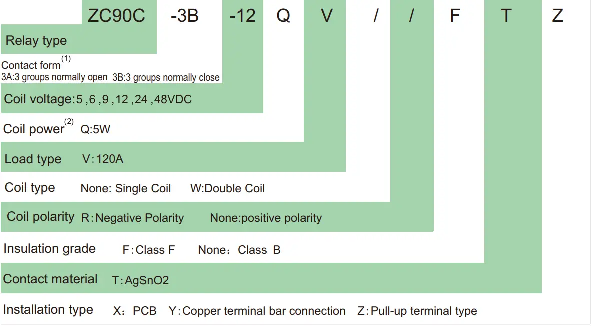
Note:
- A indicates that the contact is open when the relay leaves the factory, and B indicates that the contact is closed when the relay leaves the factory
- The single coil is 5W and the double coil is 10W
- We can make all kinds of external parts according to the customer’s requirements, see the typical example diagram for details
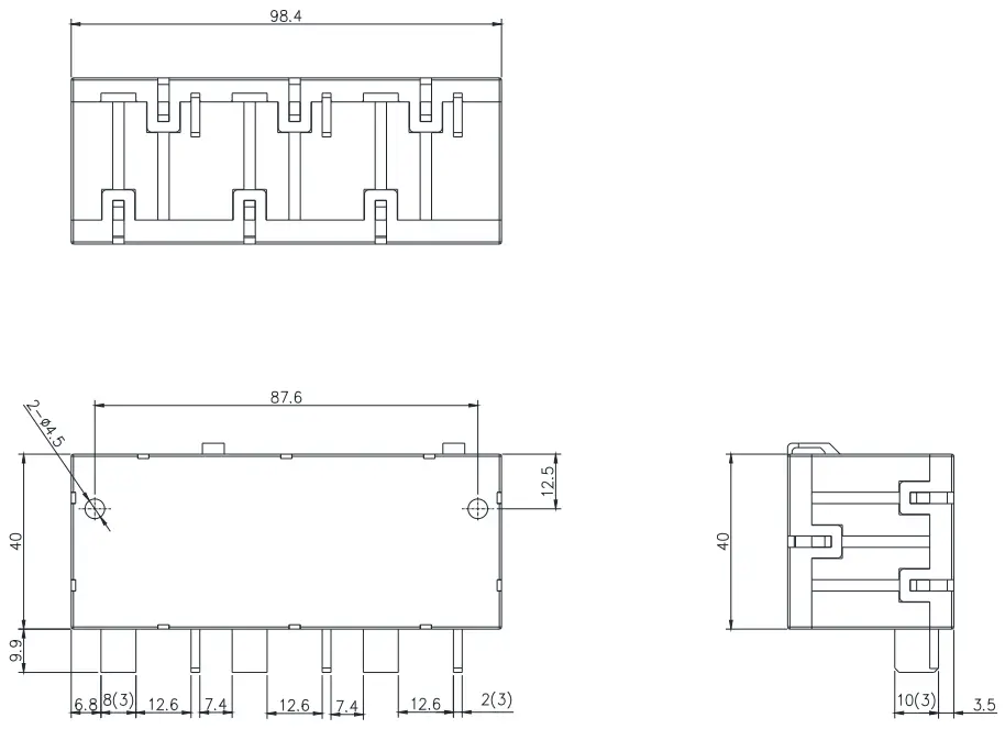
Outline size drawing, wiring diagram
Outline size drawing
Typical Case
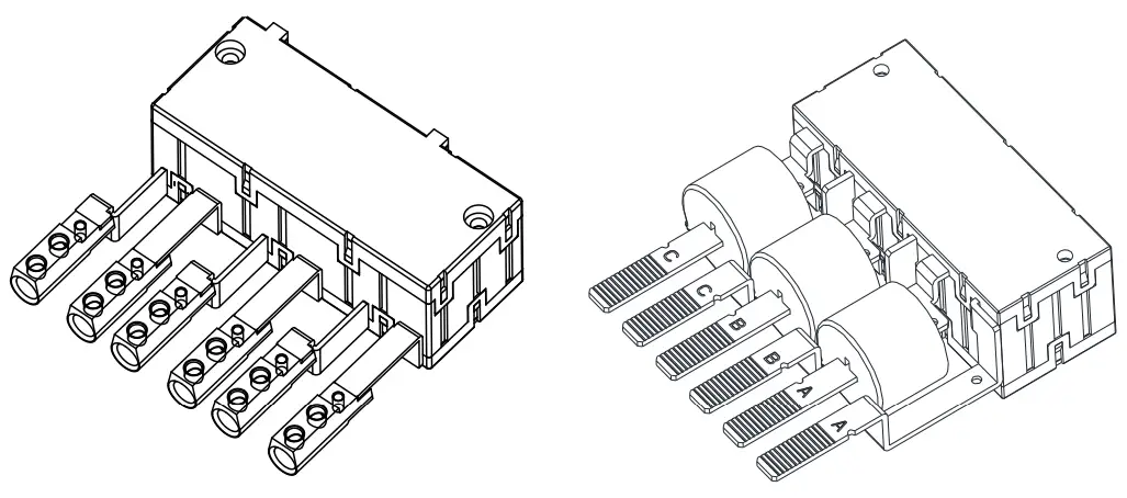
The above is a typical example of peripheral installation. Our company can accept different forms of peripheral structure customization
Note:
- The initial state of the contact may change due to transportation turbulence or other external forces, so it is recommended to use rated voltage return the contact to the desired state;
- The coil should not be applied voltage for a long time, please refer to the pulse time specified in this specification;
- The soldering temperature of the load leading end of PCB installation shall not exceed 300℃, and soldering time shall not exceed 3 seconds;
- This product is a dust-proof structure, and the storage time is recommended not to exceed 6 months.
It is recommended that contacts leave the factory in a closed state.


 User Manual")


