BETSTCO FH-LXG90R 35 Inch Tilling Width Vertical Tiller Power Harrow User Manual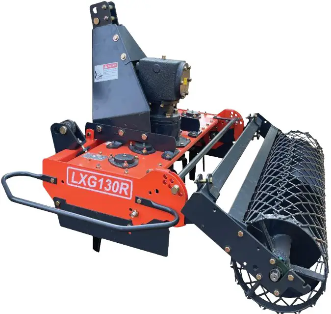
Preface
Dear Customer:
With its five tine units, the rotary power plow type power harrow is an ideal implement for tilling the soil and preparing seed-beds on farms and in vineyards or orchards, as well as for row crops and specialty crops.
Please read these operating instructions through carefully before using the rotary power harrow and strictly follow all the instructions so that the rotary harrow can be used safely and correctly, for its intended purpose.
The power harrow may only be used by persons who have the required professional know-how and who have also read and understood these operating instructions.
Please ensure that you know how to handle and operate the power harrow before using it!
General information:
- The rotary power harrow may only be used for the specified purpose: mechanical soil Village and seed-bed preparation.
- The power harrow may only be started and stopped from the tractor driver’s seat.
- No one may remain within a distance of less than 10 meters around the rotary harrow during its operation.
- The power harrow may only be operated in full daylight.
- The power harrow may only be operated when all guards and safety mechanisms are installed and fully functional.
- Malfunctions impairing safety must immediately be remedied by specialist personnel.
- The accident prevention regulations issued by the employers’ liability insurance association must be observed.
- The trañc regulations must be observed when driving on public roads.
- The PTO shaft must be disengaged from the tractor during all maintenance and repair work on the power harrow in order to prevent inadvertent start-up.
- Repairs should only be undertaken by specialist repair shops or the customer service center. The rotary power harrow should never be modified without authorization.
- The power harrow may only be operated with a PTO shaft with friction clutch.
Description of the machine
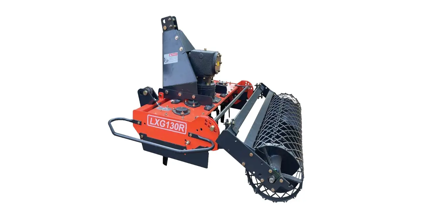
The rotary power harrow may be used for mechanical soil tillage and seed-bed preparation on farms and in vineyards and orchards, as well as for row crops and specialty crops.
Moisture remains in the soil and the water balance of the soil is maintained since the soil is not turned up as it is tilled. The vertically rotating cutters also prevent compaction of the soil, thus resulting in optimum preparation of the seed-beds.
The power harrow is mounted on the tractor by means of a three-point suspension. It has five tine units; the tine pick-up is rigidly mounted. The gear mechanism is driven via a PTO shaft and drives the cutters in the housing via gear wheels.
The working depth is set by means of a hand spindle in combination with the support roller. The friction clutch mounted on the PTO shaft protects both the harrow and the tractor from damage if overloaded. An additional machine, such as a seeder, can be connected to the rotary harrow via a further three-point suspension on the basic unit and a PTO shaft on the main gear unit. In this way, the seed-bed can be prepared and the seed sown in a single pass.
The working depth should be adjusted in line with the prevailing ground conditions in order to obtain the best possible results. Large objects should be removed from the ground beforehand so that the soil can be tilled correctly and to prevent premature wear on the tines.
The housing accommodates the various components making up the rotary power harrow. The support roller, three-point frame, angular gear and tine units are bolted onto the housing.
The three-point frame is made of robust sheet metal and bolted onto the housing. The bolts of the lower links support can be undone and the three-point frame displaced sideways on the rectangular profile of the housing for off-center operation.
The angular gear which is mounted on the housing diverts the tractor’s rotary motion through 90° and drives the tine units via gear wheels.
Each tine unit comprises a tine flange, guard plate, two tines, bearing housing, bearing and connecting elements. The tines are mounted underneath the guard plate and serve to loosen the soil. They are secured by means of special bushings, washers, bolts and lock nuts.
Start-up and operation of the machine
Before using the machine for the first time
- Read through the operating instructions for the rotary power harrow and additional attachments and ensure that you are fully familiar with the mode of operation of all units.
- Check that the length of the PTO shaft fits your tractor. The PTO shaft should include an appropriate protective mechanism!
Attachment to the tractor
- Examine tools (tines) and tine carriers for signs of wear and ensure they are secured correctly.
- Check that the support roller and three-point frame are correctly secured to the housing.
- Now connect the power harrow to the tractor by means of the three-point suspension. Secure the bolts of the upper and lower links with spring pins. Park the tractor on level ground and adjust the upper link so that the rotary power harrow is horizontal.
- Now adjust the length of the PTO shaft to match your tractor.
For this purpose, hold the two halves of the PTO shaft side-by-side in the shortest lift out position and mark it accordingly.
Shorten the inner and outer protective tube by equal amounts. Then shorten the inner and outer sliding profile by the same amount as thprotective tube. Finally round off the outer edges and carefully remove all chips. Grease the sliding profiles.
Before engaging the PTO shaft, carefully clean and grease the PTO shaft of the tractor and power harrow. Then slide the PTO shaft over the PTO shaft until the locking pin engages completely.
The friction clutch of the PTO shaft must be mounted at the machine end.
The working depth is now adjusted with the aid of the hand spindle in accordance with ground condition on a firm and level substrate or by lifting the unit completely. The power harrow with fitted tools and attachments is now ready for use.
Working with the power harrow
- The tractor PTO shaft must not be switched on until it is certain that the shaft will rotate at not more than 540 rpm at maximum engine speed.
- The PTO drive must not be engaged when the tractor drives running at full load.
- The power harrow may only be started and stopped from the tractor driver’s seat.
- The power harrow may only be switched on when there is no-one within its range of operation and hazard area (radius of 10 m from the rotary harrow) due to the risk of objects, such as stones, being hurled away from the machine. The duly prepared machine must be lowered to the working position before it is switched on. The rotary power harrow can then be switched on.
- The machine must be lowered slowly in order to avoid damage to the tools and attachments.
- During the work, the machine must be lowered to the working depth and left with the set control hydraulics. The horizontal position of the rotary power harrow can be corrected by means of the upper link.
- The areas to be tilled should be inspected for visible large obstacles before staring so that they can be removed from the harrow’s range and thus prevent damage to the tines and drive elements.
- If a reversing maneuver is required at the end of the row being tilled, the tractor PTO must be switched off and the rotary harrow allowed to come to a complete standstill before it is lifted out of the ground for the maneuver (risk of clods of earth being hurled off by the tines).
- If the frame has been fully fitted with tools, its stability will be assured even without support wheels.
- Dust clouds may form when operating the power harrow at higher speeds on dry ground. Light respiratory protection should therefore be worn when using a tractor without closed driver’s cab.
Maintenance, Care & Transport
The PTO shaft must always be disengaged and the ignition key removed before starting any maintenance and repair work on the power harrow!
Maintenance or repair work must never be performed underneath the rotary power harrow without appropriate supports. Precautions must always be taken to prevent the machine from dropping inadvertently, for instance by using hoisting gear. The rotary power harrow should always be placed on firm, level ground.
The power harrow type LXG is designed and built to require as little maintenance and care as possible.
However, the following points should be observed nevertheless:
- All nuts, bolts and screws must be examined after the first five hours of operation and then always before using the machine in order to ensure that they are secure. They must be re tightened if necessary.
- The PTO shaft must be lubricated with suficient sulphur-free grease every eight hours of operation so that it can always be extended and retracted without difficulty.
- The bearing points on the cutter unit, the spindle for setting the working depth and the roller mount must be lubricated every 30 hours of operation via the corresponding grease nipples.
- The oil must be checked every 20 hours of operation.
- Gear oil must be changed after approx. 200 hours of operation. A container must be placed under the machine to collect the escaping oil and prevent contamination of the ground. Waste oil must be disposed of in accordance with the regulations.
- The rotary power harrow should be stored in a dry place, on firm, level ground. It should be secured with chocks or similar objects to prevent inadvertent tilting.
- The machine must be thoroughly cleaned before prolonged storage. Those parts which are in contact with the ground during operation should be sprayed with corrosion inhibitor.
- Particular attention must be paid to the condition of the tines in order to ensure
maximum occupational safety and high-quality results. Before starting work, the tine must therefore be examined to ensure they are correctly secured and wear down evenly. Bent tines must be replaced immediately. - Vibrations in the rotary power harrow are usually due to imbalances in the tine unit and may damage the machine. Switch off the rotary power harrow and the tractor if the vibrations increase significantly during operation or if the machine’s running noise changes suddenly. The cause must be located and remedied before resuming work.
- When cleaning the machine with a high-pressure cleaner, care must be taken not to direct the high-pressurejet against bearings and seals, as this can result in malfunctions and premature failure of the machine.
- The screw connections between tines and tine flange / guard plate must be checked regularly. Always fit new lock nuts and new washers whenever the screw connections have been removed. The condition and degree of wear on the tines and tine pick up must be checked regularly.
- When transporting the machine, care must be taken to ensure that there is no one and nothing in the immediate vicinity when slung outwards with the tractor.
- The power harrow should only be repaired by a specialist repair shop or a authorized customer service center.
Changing and regrinding tines:
Tines should only be reground and changed by your dealer, since considerable hazards can arise if they are fitted incorrectly.
Removal of the tines:
- First switch off the tractor and remove the ignition key.
- Disengage the PTO shaft and then the rotary power harrow from the tractor.
- Remember to support it so that it cannot tip over inadvertentlv
- Turn the power harrow over with the aid of hoisting gear so that the tines can be reached without difficulty.
- Remove the fastening bolt and nut with a suitable wrench.
- Important: For safety reasons, new self-locking nuts and new washers must always be used whenever the tints are changed.
Ensure that the tines are fitted correctly in the direction of rotation.
Installation of the tines:
- Fit the tines in the correct order.
- Fit the fastening bolt, washers and nut.
- Tighten the self-locking nut twice.
Regrinding the tines:
If the tines have to be reground, care must be taken to ensure that each pair of tines in the tine unit is reground. This prevents the tine unit concerned becoming imbalanced.
Use the transport aids or three-point hitch provided on the housing to transport and handle the power harrow.
Safety Instructions
- The Implements may only be used when all safety mechanisms are in place and fully functional.
- All faults capable of impairing safety must immediately be remedied by specialist personnel.
- The operating instructions of any additional attachments installed must be read through carefully and observed.
- Never climb onto the tractor or leave it unattended when the PTO shaft is running.
- Never allow anyone who is not familiar with the safety and operating instructions to use the machine.
- Remove all visible large objects which may be picked up and hurled aside by the rotary power harrow. Particular attention must be paid to loose wires on the ground. Adjust your driving speed in line with the ground conditions and prevailing circumstances.
- No one may remain within 10 meters of the power harrow during operation of the machine. High risk of injury due tomoving machine parts and objects being hurled away from the machine, such as stones, etc.
- Never climb or reach in between the power harrow and the tractor with your arms or legs during operation of the machine — high risk of injury! (This is only permitted when the machine has been lowered to the ground and the tractor switched off.)
- The machine should only be operated in full daylight . Traffic regulations must be observed when driving on public roads. Adequate illumination must be ensured when driving in twilight or darkness (A detachable set of lights is recommended.)
- Never climb or reach in between the support roller and cutter unit with your arms or legs — high risk of injury.
- Always wear tightly fitting clothes so that these cannot be caught between rotating parts of the machine.
- Safety stickers must be kept clean and observed!
- Never open or remove the guard elements during operation. Worn or defective parts must immediately be replaced by new parts.
- The cutter unit must never be operated when the power harrow is lifted off the ground.
- Driving a tractor on steep slopes can be dangerous. If work on steep slopes is unavoidable, great care should be exercised. Do not take bends too tightly.
- No one may ever ride on the machine either during operations or while it is being transported, not even over short distances.
- Always examine the rotary power harrow for signs of damage following a collision with any objects. Such damage must always be repaired before resuming work.
- Maintenance and repair work may only be carried out when the PTO shaft and machine have been disengaged form the tractor.
- Never crawl under a rotary power harrow which is still connected to the tractor, as the machine may be lowered at any time — high risk of injury.
- The accident prevention regulations of the employers’ liability insurance association must be observed when using the machine.
- When traveling round bends, take account of the larger width / length (turning circle) and considerable weight of the rotary power harrow.
- Ensure that the PTO shaft halves and protective tubes overlap as prescribed, both in the transport position and in the working position. Read the operating instructions for the PTO shaft in this context.
- The PTO shaft should only be engaged and disengaged when the tractor engine is switched off and the ignition key has been removed.
Technical Data
| MODEL | LXG-130 (1801.3) | LXG-170 (11301.7) | LXG-200 (1802.0) | ||||||
| SPECIFICATION | Inch | Metric | Inch | Metric | Inch | Metric | |||
| Structure Weight | 617.31b | 280kg | 727 51b | 330kg | 837 7Ib | ||||
| Gear Box HP | 50hp | 50hp | 50hp | ||||||
| No of Blade | 12 | 16 | 18 | ||||||
| Tilling Width | 51 2″ | 1300mm | 66.9″ | 1700mm | 78 7″ | 2000mm | |||
| Tilling Depth | 7 9″ | 200mm | 7 9″ | 200mm | 7 9″ | 200mm | |||
| PTO Turning Speed | 540rmin | 540rimin | 540r/min | ||||||
| Tractor HP | 25-35hp | 40-70hp | 55-80hp | ||||||
Safety Decals


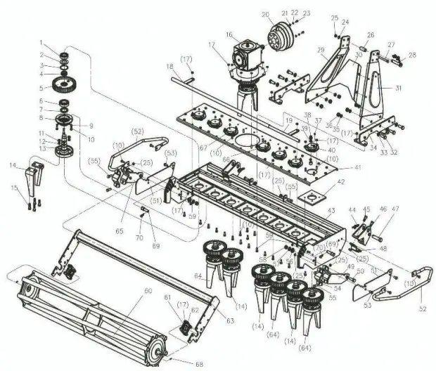
Parts Manual
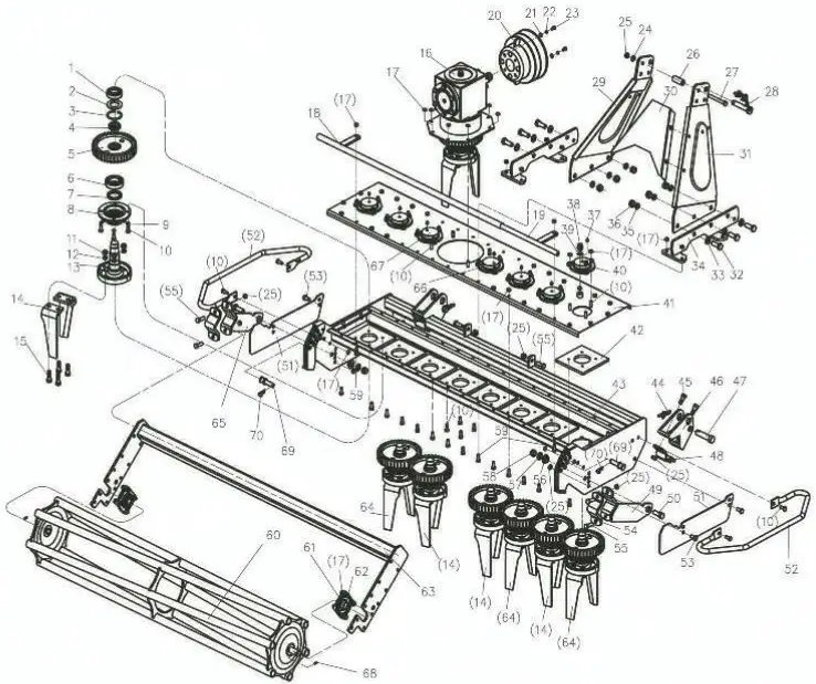
| R0. | PvtMO. | Ssme &Specif ications | Quantity | Remark |
| 1 | UB 278-89 | Beariaz 600a | 7 | |
| 2 | LXtil 70. 115 | Big washer | 7 | |
| 3 | GB 891.1 198fi | 3eo wr ra g T2 | 7 | |
| 4 | 166170.116 | Selflocking nul 1139×1.5 | 7 | |
| 5 | 1.16110.118 | Export gear (two) | 7 | |
| 6 | GlIT 276 94 | Bearing 6209 | 7 | |
| 7 | GB 131371 — 1992 | Oi I seal F8 SO x 68 x 8 | 7 | |
| 8 | 1X6170.112 | Rotor support down papel (twn ) | 7 | |
| 9 | GB 93-67 | ?usher 10 | 32 | |
| f0 | GB 5783-86 | Bolt 1110 x 35 | 32 | |
| GB 6170-86 | ||||
| 12 | GB 9 R7 | Masher 14 | 32 | |
| 13 | 1.4(6170. II | It sing sent | 7 | |
| 14 | I.XG170. 109 | Co her ofie ) | 8 | |
| 15 | GB 6782-86 | Bolt R14x60 | 32 | |
| 16 | 1XG1/0. 011 | (Year case ossesbly | 1 | |
| IT | GB6184-86 | S1x coma lockout R10 | 7T | |
| LS | 1XG170.0:9 | Staff gauge joint ing (one) | 1 | |
| 19 | 1.X6170.020 | Staff gunge joint i rat (Lno) | 1 | |
| 20 | A1120. 00. 401 | Cover | 1 | |
| 21 | GB97. 1-8S | Washer 8 | 2 | |
| 22 | GB93— B7 | Vasher 8 | 2 | |
| 23 | 685183-86 | Solt R8x16 | 2 | |
| 2f | GB 97.1-8o | 3asher 12 | 2 | |
| 25 | 066t64•86 | O. x Corner lockout M12 | 2 | |
| 26 | M TOS.ItIO | Bushing | 2 | |
| 27 | 0135782-86 | Bolt dl 2×100 | 2 | |
| 28 | EFLOO. 00. Ot9 | Above awes pin | 1 | |
| 29 | LX0110. 029 | Sx 3rd Out | 1 | |
| 30 | LXGt70. 101 | Reinforcement | 1 | |
| 31 | 12(6170. 028 | Dx 3rd point | I | |
| 32 | GB ST82-86 | Bolt B16x4S | 6 | |
| 33 | ?8 9Y. 1-6S | tiasher 16 | 6 | |
| 34 | 1X6170.012 | lelpendend connect f i xi n g joi ii | 2 | |
| 35 | G1R 93-6Y | Vasher 16 | 6 |
| 36 | Go 6170-8o | \ut 1116 | 6 | |
| 37 | GB11S2-S9 | frank press oiling cup M1081 | 8 | |
| 38 | CBS’ | .derate bolt di screteness | 2 | |
| 39 | 03541-8-1 | Washer 16 | 2 | |
| 40 | LXG170. 102 | Rotor su 01 I above el (one | 6 | |
| 41 | LXG1?0. 015 | Above cover boort jointing | 1 | |
| 42 | LXG170. 132 | Mat | 8 | |
| 43 | LX0170, OU | Engine rack bourn i ng | 1 | |
| 14 200. 56. 011 | Snap pin chain | 2 | ||
| 45 | GB 67b3—.86 | Bolt 1112s40 | 4 | |
| 46 | LXG170. 130 | St irrup(two) | 2 | |
| 47 | LXG170. 106 | Pin (one) | 2 | |
| 48 | LXG1?0. Ul | Sun one) | 2 | |
| ’19 | LXG170. OU | mil i I rack right connect joi | 1 | |
| 50 | GB 4788 BU | Bolt M16z45 | 2 | |
| 31 | LX(il 70. 122 | Sh of it | 2 | |
| 02 | LXG1?0, 1111 | Shield rack | 2 | |
| .53 | SB 5783-811 | B.olt M12x30 | 4 | |
| 54 | RT150. 101 | U bolt | 2 | |
| 3S | GB 5183-86 | Six corner Plcl t | IR | |
| 56 | LXGI TO IN.S | Push | 2 | |
| 57 | GB 9/,1-85 | Washer 16 | 2 | |
| 38 | 013 0184 B6 | Slx corner 1 ocknu t MU | 2 | |
| 59 | CA 58386 | En t 1110×30 | 10 | |
| 60 | WG7. 024 | unInt t intblenent joint lag | 1 | |
| 61 | GB/T 7810-1 995 | Sprareness beorin g f 1CFU205 | 2 | |
| 62 | GB 6?83-88 | Bolt lifPx40 | 8 | |
| 63 | UGC70. 025 | Un I n i 1 impJeoent connect rack | 1 | |
| 01 | LX?170. 109 | t ultul (tau) | 8 | |
| 65 | UG VTO. 017 | Urchnit rack left connect join | 1 | |
| 66 | iscei TO. 10Z | Motor support above panel (twc | I | |
| 67 | 1.SG0 70. 105 | Rotor supiprr above 0 nel (thl | 1 | |
| 66 | iiii 679—do | pin 8×36 | 2 | |
| 69 | LXG170. 250 | pin | 2 | |
| 70 | a 2′. 106 | pin | 2 | |
| NO. | Port N0. | Nwe àSgecJ fi cat ions | 9uanti tx | Remark |
| 0B57BS —R6 | Bolt H10x25 | 10 | ||
| 2 | 0B93—67 | washer 10 | 1? | |
| 3 | 1G—150. 0l. II6 | Front. cover | 1 | |
| 4 | 1C—150. 01. llfi | Front rasket | 1 | |
| 5 | IIfi4 8S2 67 | 0i 1 seal PDS8x5.F | 1 | |
| üB2H7 h4 | Bearing 7208E | 1 | ||
| 1G—150. 0l. 117 | ‘frwsmission shaft | 1 | ||
| làs 150. 0l. lls | Gearbox | 1 | ||
| 9 | CP8-OO. Ol1 | Breather plug | 1 | |
| 10 | CBP 00. 104 | Washer | 2 | |
| 1G1S0. 02—04 | Smallcone—shaped gear | 1 | ||
| 12 | GB29I—84 | Bearing ?310E | 1 | |
| lfi 150. 01. lll | Bark end rasket | 1 | ||
| U | 1G-150.01.110 | Back end cover | 1 | |
| 15 | 1G—150. 01. 131 | Nut h30xl. S | 1 | |
| 16 | U—150. 01. 132 | Lnck en her | 2 | |
| 1G 150. 04 08 | Big cone ahaped gear | 1 | ||
| 18 | 6B/T 276-91 | Bearing 6311 | 1 | |
| U | üB 138M – 1M2 | 0i I sent 50x68x8 | 10 | |
| 20 | WG170. 138 | Sushingftvo) | l | |
| 31 | TWt50. 0L ï14 | Cnsket | I | |
| 22 | LXC Ï T0. 026 | |||
| LB 70-ü5 | ||||
| 2é | mü1?0. 136 | 0ut.put a:les | 1 | |
| LII 170. 13.5 | Pushing | l | ||
| 2fi | £XCTO.133 | Output gear (nnel | 1 | |
| 27 | üB/T 2Tò—94 | Bearing ti2ll | 1 | |
| 28 | LlG170.128 | Gasket. | 8 | |
| 29 | % 13871 — 1992 | Oil seal PB—60x80x8 | 1 | |
| 30 | lXG170.147 | Bearing seat (one) | 1 | |
| 31 | GB 6170—B6 | Nut HU | 34 | |
| 32 | 0ü 93—87 | Washer 14 | 52 | |
| 93 | LX01T0. t26 | Cnlter sett ing seat | 1 | |
| ?4 | WC 170. t21 | Coltf:r Otto) | P | |
| 35 | UB 5Tü2—fï6 | Bolt lI14x40 | :12 | |
| 3ó | LkC170. US | \ïasher 30 | 1 | |
| 37 | 1ti—150. 01. 131 à | Nu t fl30x 1. 5x 14 | 1 |
Parts Request Form
Phone 541-895-3083 or E-mail
[email protected]
Name:——————-
Address:———————-
City State Zip:—————–
Phone:——————-
E-mail:—————-
Model Number:—————–
Serial Number:————-
Purchased From:——————
Purchase Date:————–
| Item•No. | Description | QtY | Price | Amount |
FARMER-HELPER Limited Warranty
Unless otherwise stated on purchase invoice, Betstco warrants to original Purchaser that Farmer-Helper products are free from major deffects in material under normal use and service for a period of 90 Days from the date the product is purchased or shipped, whichever is later. Commercial use 90 days. Use at address that is not yours, is considered commercial use. Consumable, Expendalble, Wear Items (Rubber plastic parts, hydraulic hoses, belts, tires, cables, blades, tines, wedges, teeth, tiups, chains, pins, brushes, filters, etc) and cracked hydraulic pumps, bent or broken cylinder rods are not covered under this warranty. Warranty does not cover items that have been modified, damaged by abuse or usage not in accordance with design or maintenance.
Betstco obligation under this warranty is to repair or replace defective upon approval by; Betstco, 83371 Melton Rd. N, Creswell OR 97426 that Warranty Claim is valid. Product shall be returned upon request of Betstco. Transportation charges to be prepaid by user. Gasoline or diesel engines used to powered Farmer-Helper products are covered by the warranty of the appropriate engine manufacturean Purchaser must look to the engine manufacture for all issues relating to engine operation.
Betstco assumes no responsibility for outside labor
PERMISSABLE BY APPLICABLE LAW, BETSTCO HEREBY DISCLAIMS ALL WARRANTIES OF ANY KIND, EITHER EXPRESS OR IMPLIED, INCLUDING, ANY IMPLIED WARRANTIES WITH RESPECT TO THE PRODUCT PURCHASED, WITHOUT LIMITING THE GENERALITY OF THE FOREGOING, BETSTCO HEREBY EXPRESSLY DISCLAIMS ALL LIABILITY FOR PRODUCT DEFECT OR FAILURE, CLAIMS THAT ARE DUE TO NORMAL WEAR, PRODUCT MISUSE, ABUSE, PRODUCT MODIFICATION, IMPROPER PRODUCT SELECTION, NON-COMPLIANCE WITH ANY CODES, OR MISAPPROPRIATION. BETSTCO MAKES NO WARRANTIES TO THOSE DEFINED AS “CONSUMERS” IN THE MAGNUSON-MOSS WARRANTY FEDERAL TRADE COMMISION IMPROVEMENTS ACT. THE FOREGOING EXCLUSION OF IMPLIED WARRANTIES DO NOT APPLY TO THE EXTENT PROHIBITED BY LAW. PLEASE REFER TO YOUR LOCAL LAWS FOR ANY SUCH PROHIBITIONS.
THERE SHALL BE NO LIABILITY FOR PRODUCT LIABILITY OR LIABILITY ON THE PART OF BETSTCO FOR ANY GENERAL SPECIAL OR CONSEQUENTIAL DAMAGES ARISING OUT OF THE SALE OR USE OF ANY PRODUCTS SOLD BY BETSTCO OR AN AGENT THEREOF, BETSTCO MAKES NO WARRANTIES, EXPRESS OR IMPLIED, (INCLUDING, BUT NOT LIMITED TO, ANY WARRANTY OF MERCHANTABILITY OR FITNESS OF THE PRODUCTS FOR ANY PURPOSE) WITH RESPECT TO THE PRODUCTS COVERED BY THIS AGREEMENT EXCEPT AS IN THIS PARAGRAPH OTHERWISE EXPRESSLY PROVIDED.
THIS IS THE SOLE AND ONLY WARRANTY OF VALUE-LEADER PRODUCTS, NO OTHER WARRANTY IS APPLICABLE, EITHE EXPRESSED OR IMPLIED, IN FACT BY LAW.
This warranty shall not be interpreted to render Betstco, or any authorized agent liable for injury or damages of any kind or nature, direct, consequential, or contingent, to a person or property.
The sole and only remedy in regard to any defective product shall be the repair or replacement thereof as herein provided, Betstco, agent(s) of Betstco shall not be liable for any consequential, special, incidental or punitive damagesresulting from or caused by any such defects
Betstco reserves the rights to make improvements in design or changes in specifacations at any time, without incurring any obligations to owners of the units previously sold.
WARRANTY VOID IF REGISTRATION IS NOT RECEIVED OR RECORDED ONLINE WITHIN 30 DAYS OF PURCHASE DATE OR SHIP DATE, WHICHEVER IS LATER
ITEM:—————– MODEL# PURCHASE DATE:—————-
PURCHASED FROM:—————— GIFT INV# ORDER#—————
OWNER NAME:——————–SERIAL #————-
OWNER ADDRESS:—————————
CITY:———————–
PHONE:————————-
COUNTY: —————ST:——————-
EMAIL:—————-
ACCEPTANCE OF RESPONSIBILITY:
I (PURCHASER) HAVE READ OPERATORS MANUAL AND LIMITED WARRANTY OR SOMEONE HAS READ/AND EXPLAINED ALL INSTRUCTIONS TO ME. I UNDERSTAND THIS WARRANTY DOES NOT COVER ANY LABOR AND THAT ALL DISPUTES WILL BE SETTLED BY BINDING ARBITRATION. BINDING ARBITRATION IS CONDUCTED BY THE BETTER BUSINESS BUREAU (BBB) LOCATED AT 4004 SW KRUSE WAY PLACE ST 375 LAKE OSWEGO OR 97035 OR THE CURRENT BBB LOCATION CLOSEST TO BETSTCO. I ACKNOWLEDGE MY LIMITED WARRANTY IS VOID IF ANY ATTEMPT TO REPAIR OR REPLACE DEFECTIVE PARTS HAS BEEN MADE BY UNAUTHORIZED PERSONNEL.I ACKNOWLEDGE RECEIPT OF MY OPERATORS MANUAL AND HAVE READ THE SAFE OPERATION SECTION. I ACKNOWLEDGE UNDERSTANDING MAINTENANCE AND SAFE OPERATION REQUIREMENTS, ITEM SPECIFACATIONS, OPERATION, CONTROLS AND STORAGE REQUIRMENTS. I UNDERSTAND THAT IS ALONE AM RESPONSIBLE FOR PROPER MAINTENANCE, CARE AND SAFE OPERATIONOF THIS
FARMER-HELPER ITEM
I (PURCHASER) AGREE THAT PERSONS NOT FAMILIAR WITH THE OPERATION OF THIS ITEM SHOULD NOT BE ALLOWED TO USE IT. CHILDREN ESPECIALLY SHOULD NOT OPERATE OR BE NEAR POWER PRODUCTS WHEN IN USE. ANYONE OPERATING VALUE-LEADER PRODUCTS SHOULD HAVE READ OPERATIONS MANUALS AND SAFTEY MANUALS
OWNERS SIGNATURE:—————- x DATE:—————
YOU MUST SIGN THIS WARRANTY AND MAIL OR FAX A COPY TO BETSTCO, 83371 MELTON RD, CRESWELL OR, 97426. IF YOU PREFER YOU MAY COMPLETE YOUR REGISTRATION ONLINE AT WWW.VALUE-LEADER.COM. THIS WARRANTY IS NOT EFFECTIVE UNLESS PURCHASER COMPLETE REGISTRATION AND WARRANTY FOR WITHIN 30 DAYS OF PURCHASE OR SHIP DATE WHICHEVER IS LATER.
NOTE: WE MAY REFUSE WARRANTY OF ANY KIND UNLESS BETSTCO, RECEIVES A COMPLETED, LEGIBLE AND SIGNED WARRANTY REGISTRATION. IT IS THE RESPONSIBILITY OF THE PURCHASER TO ASSURE THAT REGISTRATION DOCUMENT IS RECIEVED BY
1 YEAR EXTENDED WARRANTY & REGISTRATION
FARMER-HELPER IMPLEMENTS
BRANDED PRODUCTS
1 YEAR EXTENDED WARRANTY
1 Year Extended Warranty amendsto original Recorded Warranty Registration the time period of described coverage. Extended Warranty does not apply to consumable and Expendable Item as described in Product Warranty Registration.
This amendment does not affect any other part of recorded Warranty Registration or policy.
No one is authorized to alter, modify, or enlarge this Amendment to original recorded Warranty Registration
EXTENDED REGISTRATION & PAYMENT MUST BE RECEIVED WITHIN 30 DAYS OF PURCHASE DATE
EXTENDED WARRANTY REGISTRATION
PRODUCT & MODEL #—————————
SERIAL #—————————–
OWNER NAME :———————————-
BETSTCO INVOICE #————————–
ACCEPTANCE OF RESPONSIBILITY:
I (PURCHASER) HAVE READ AND UNDERSTAND THE EXTENDED WARRANTY OR SOMEONE HAS READ AND EXPLAINED ALL THE ABOVE TO ME. I UNDERSTAND THIS EXTENDED WARRANTY DOES NOT COVER ANY LABOR. I HAVE FILED MY ORIGINAL WARRANTY REGISTRATION AND FULLY UNDERSTAND MY REQUIREMENTS. I UNDERSTAND THAT I ALONE AM RESPONSIBLE FOR PROPER MAINTENANCE, CARE AND SAFE OPERATION OF THIS TRACTOR IMPLEMENT.
OWNERS SIGNATURE:—————- x DATE:————-
FAX TO 1-541-895-2756
YOU MUST SIGN THIS WARRANTY AND MAIL OR FAX A COPY TO BETSTCO, 83371 MELTON RD, CRESWELL OR. IF YOU PREFER YOU MAY COMPLETE YOUR REGISTRATION ONLINE AT WWW.VALUE LEADER.COM. THIS WARRANTY IS NOT EFFECTIVE UNLESS PURCHASER COMPLETE REGISTRATION AND WARRANTY FOR WITHIN 30 DAYS OF PURCHASE OR SHIP DATE WHICHEVER IS LATER.
NOTE: WE MAY REFUSE WARRANTY OF ANY KIND UNLESS BETSTCO, RECEIVES A COMPLETED, LEGIBLE AND SIGNED WARRANTY REGISTRATION. IT IS THE RESPONSIBILITY OF THE PURCHASER TO ASSURE THAT REGISTRATION DOCUMENT IS RECIEVED BY BETSTC


