Braber Equipment BE-TL85 TL Rotary Tillers User Manual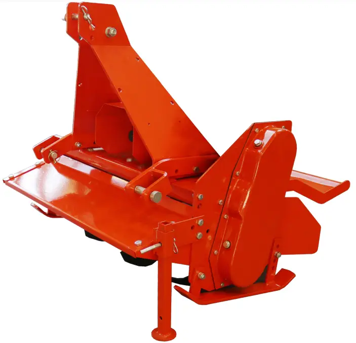
INTRODUCTION
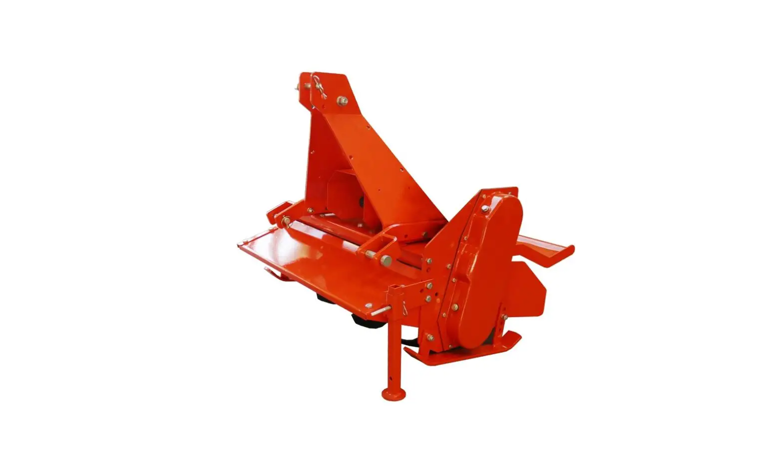
Thank you for purchasing your Tiller. Your rotary tiller is design to be used on 540 rpm tractors. It is important to properly maintain and keep in place all safety guards and shields that came with your tiller. SAFETY
Read and understand this manual and all safety signs before operating and maintaining. Review the safety instructions and precautions annually.
TAKE NOTE! THIS SAFETY ALERT SYMBOL FOUND THROUGHOUT THIS MANUAL IS USED TO CALL YOUR ATTENTION TO INSTRUCTIONS INVOLVING YOUR PERSONAL SAFETY AND THE SAFETY OF OTHERS. FAILURE TO FOLLOW THESE INSTRUCTIONS CAN RESULT IN INJURY OR DEATH.
![]() THIS SYMBOL MEANS ATTENTION! BECOME ALERT! YOUR SAFETY IS INVOLVED!
THIS SYMBOL MEANS ATTENTION! BECOME ALERT! YOUR SAFETY IS INVOLVED!
SAFETY SIGNAL WORDS
Note the use of the signal words DANGER, WARNING and CAUTION with the safety messages. The appropriate signal word for each has been selected using the following guidelines:
![]() DANGER:
DANGER:
Indicates an imminently hazardous situation that, if not avoided, will result in death or serious injury. This signal word is to be limited to the most extreme situations typically for machine components which, for functional purposes, cannot be guarded.
![]() WARNING:
WARNING:
Indicates a potentially hazardous situation that, if not avoided, could result in death or serious injury, and includes hazards that are exposed when guards are removed. It may also be used to alert against unsafe practices.
![]() CAUTION:
CAUTION:
Indicates a potentially hazardous situation that, if not avoided, may result in minor or moderate injury. It may also be used to alert against unsafe practices.
GENERAL SAFETY GUIDELINES
Safety of the operator is one of the main concerns in designing and developing a new piece of equipment. Designers and manufacturers build in as many safety features as possible. However, every year many accidents occur which could have been avoided by a few seconds of thought and a more careful approach to handling equipment. You, the operator, can avoid many accidents by observing the following precautions in this section. To avoid personal injury, study the following precautions and insist those working with you, or for you, follow them.
Replace any CAUTION, WARNING, DANGER or instruction safety decal that is not readable or is missing. Location of such decals is indicated in this booklet.
Do not attempt to operate this equipment under the influence of drugs or alcohol. Review the safety instructions with all users annually.
This equipment is dangerous to children and persons unfamiliar with its operation. The operator should be a responsible adult familiar with farm machinery and trained in this equipment’s operations. Do not allow persons to operate or assemble this unit until they have read this manual and have developed a thorough understanding of the safety precautions and of how it works.
To prevent injury or death, use a tractor equipped with a Roll Over Protective System (ROPS). Do not paint over, remove or deface any safety signs or warning decals on your equipment. Observe all safety signs and practice the instructions on them.
Never exceed the limits of a piece of machinery. If its ability to do a job, or to do so safely, is in question – DON’T TRY IT.
SAFETY DECAL CARE
- Keep safety signs clean and legible at all times.
- Replace safety signs that are missing or have become illegible.
- Replaced parts that displayed a safety sign should also display the current sign.
- Safety signs are available from your Distributor or Dealer Parts Department or the factory.
How to Install Safety Signs:
- Be sure that the installation area is clean and dry.
- Decide on the exact position before you remove the backing paper.
- Remove the smallest portion of the split backing paper.
- Align the decal over the specified area and carefully press the small portion with the exposed sticky backing in place.
- Slowly peel back the remaining paper and carefully smooth the remaining portion of the decal in place.
- Small air pockets can be pierced with a pin and smoothed out using the piece of decal backing paper.
BEFORE OPERATION
- Carefully study and understand this manual.
- Do not wear loose-fitting clothing, which may catch in moving parts.
- Always wear protective clothing and substantial shoes.
- Assure that all tires are inflated evenly.
- Give the unit a visual inspection for any loose bolts, worn parts or cracked welds, and make necessary repairs.
- Follow the maintenance safety instructions included in this manual.
- Be sure that there are no tools lying on or in the equipment.
- Do not use the unit until you are sure that the area is clear, especially children and animals.
- Don’t hurry the learning process or take the unit for granted. Ease into it and become familiar with your new equipment.
- Practice operation of your equipment and its attachments. Completely familiarize yourself and other operators with its operation before using.
- Use a tractor equipped with a Roll Over Protective System (ROPS) and fasten your seat belt prior to starting the engine.
- The manufacturer does not recommend usage of tractor with ROPS removed.
- Move tractor wheels to the widest recommended settings to increase stability.
- Securely attach to towing unit. Use a high strength, appropriately sized hitch pin with a mechanical retainer and attach safety chain.
- Do not allow anyone to stand between the tongue or hitch and the towing vehicle when backing up to the equipment.
DURING OPERATION
- Children should not be allowed on the product.
- Clear the area of small children and bystanders before moving the feeder.
- If using a towing unit, securely attach feeder by using a hardened 3/4” pin, a metal retainer, and safety chains if required. Shift towing unit to a lower gear before going down steep downgrades, thus using the engine as a retarding force. Keep towing vehicle in gear at all times. Slow down for corners and rough terrain.
- Make sure you are in compliance with all local and state regulations regarding transporting equipment on public roads and highways. Lights and slow-moving signs must be clean and visible by overtaking or oncoming traffic when feeder is transported.
- Beware of bystanders, particularly children! Always look around to make sure that it is safe to start the engine of the towing vehicle or move the unit. This is particularly important with higher noise levels and quiet cabs, as you may not hear people shouting.
- NO PASSENGERS ALLOWED – Do not carry passengers anywhere on, or in, the tractor or equipment, except as required for operation.
- Keep hands and clothing clear of moving parts.
- Do not clean, lubricate or adjust your equipment while it is moving.
- When halting operation, even periodically, set the tractor or towing vehicle brakes, disengage the PTO, shut off the engine and remove the ignition key.
- Be especially observant of the operating area and terrain – watch for holes, rocks or other hidden hazards.
- Always inspect the area prior to operation.
- DO NOT operate near the edge of drop-offs or banks.
- DO NOT operate on steep slopes as overturn may result.
- Operate up and down (not across) intermediate slopes. Avoid sudden starts and stops.
HIGHWAY AND TRANSPORT OPERATIONS
- Adopt safe driving practices:
- Keep the brake pedals latched together at all times. NEVER USE INDEPENDENT BRAKING WITH MACHINE IN TOW AS LOSS OF CONTROL AND/OR UPSET OF UNIT CAN RESULT.
- Always drive at a safe speed relative to local conditions and ensure that your speed is low enough for an emergency stop to be safe and secure. Keep speed to a minimum.
- Reduce speed prior to turns to avoid the risk of overturning.
- Avoid sudden uphill turns on steep slopes.
- Always keep the tractor or towing vehicle in gear to provide engine braking when going downhill. Do not coast.
- Do not drink and drive!
- Comply with state and local laws governing highway safety and movement of farm machinery on public roads.
- Use approved accessory lighting flags and necessary warning devices to protect operators of other vehicles on the highway during daylight and nighttime transport. Various safety lights and devices are available from your dealer.
- The use of flashing amber lights is acceptable in most localities. However, some localities prohibit their use. Local laws should be checked for all highway lighting and marking requirements.
- When driving the tractor and equipment on the road or highway under 40 kph (20 mph) at night or during the day, use flashing amber warning lights and a slow moving vehicle (SMV) identification emblem.
- Plan your route to avoid heavy traffic.
- Be a safe and courteous driver. Always yield to oncoming traffic in all situations, including narrow bridges, intersections, etc.
- Be observant of bridge loading ratings. Do not cross bridges rated lower than the gross weight as which you are operating.
- Watch for obstructions overhead and to the side while transporting.
- Always operate equipment in a position to provide maximum visibility at all times. Make allowances for increased length and weight of the equipment when making turns, stopping the unit, etc.
- Pick the levelest possible route when transporting across fields. Avoid the edges of ditches or gullies and steep hillsides.
- Be extra careful when working on inclines.
- Maneuver the tractor or towing vehicle at safe speeds.
- Avoid overhead wires or other obstacles. Contact with overhead lines could cause serious injury or death.
- Avoid loose fill, rocks and holes; they can be dangerous for equipment operation or movement.
- Allow for unit length when making turns.
- Operate the towing vehicle from the operator’s seat only
- Never stand alongside of unit with engine running or attempt to start engine and/or operate machine while standing alongside of unit.
- Never leave running equipment attachments unattended.
- As a precaution, always recheck the hardware on equipment following every 100 hours of operation. Correct all problems. Follow the maintenance safety procedures.
OPERATION
Before attaching the rotary tiller to the tractor, check the unit to ensure there is oil in the top and side gearbox. See Maintenance section for lubricant specifications.
![]() BEFORE BEGINNING OPERATION, CHECK OIL AND GREASE POINTS.
BEFORE BEGINNING OPERATION, CHECK OIL AND GREASE POINTS.
Oil level: Top gearbox 1 1/2” from the end of the dip stick. When sitting slightly tilted forward, oil should at the bottom of the drain plug on the side gearbox cover.
Grease: Right Rotor bearing, PTO shaft Cross & Bearings
Attaching to the tractor
- With the Rotary Tiller on a level surface, back the Cat. 1 tractor so the tractor lift arms are even with the unit’s lower hitch pins. Lower or raise the tractor hitch arms until the 7/8” bushing in the arm is inside the clevis of lower hitch points. Be sure nothing is between the tractor and the tiller before backing up.
- Insert the lower hitch pin through the lower hitch blocks and the tractor arm. The YCT series tillers have adjustable lower hitch blocks that can be slide to facilitate usage on larger tractors.
- Secure the lift arm in place by using a 7/16” lynch pin or other fastener.
- Repeat with the other arm.
- Connect the drive line to the tractor’s PTO output shaft. Secure it in place.
- Connect the tractor top link to the upper hitch point of the rotary tiller.
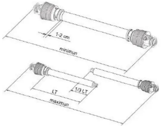
- Start the tractor and slowly raise the tiller. Check for drawbar interference. Be sure that the PTO driveline does not bottom out when lifting the machine to its maximum height. If it does appear that it could bottom out, it is necessary to shorten the PTO driveline. (See Shortening a PTO Driveline section). Ensure that in the working position there is an overlap of a minimum of 1/3 the length of each profile.
Shortening a PTO Driveline
- With the implement attached to the tractor’s three-point hitch, and the PTO driveline not installed, separate the PTO driveline. Attach the implement end to the implement and the other end to the tractor PTO input shaft.
- Raise the implement by using the tractor’s hydraulic 3-point hitch to its maximum lift height.
- Hold the half shafts next to each other and mark them so each end is approximately ½” from hitting the end of the telescopic profiles.
- Shorten the inner and out guard tubes equally.
- Shorten the inner and outer profiles by the same length as the guard tubes. Using a rattail file, round off all sharp edges and burrs. Grease the telescopic profile generously before reassembling.

![]() CAUTION:
CAUTION:
Do not shorten too much, the proper overlap is a minimum of 1/3 the length of each profile.
Caution: Slip Clutches may become hot. Do Not Touch. Keep the slip clutch area clear of a material that may catch fire.
Slip clutches have adjustable torque settings. The torque setting varies with the different compression of each spring. All the springs should have an equal amount of compression.
IMPORTANT: Do not over-tighten the compression nuts as this may impair performance or cause premature wearing of the slip clutch.
Slip Clutch adjustments
Slip Clutch must be adjusted before first use or after a storage period.
- Using a marker, scribe a line across the exposed edges of the clutch plate and friction discs.
- Back off compression nuts to free friction discs by turning each nut exactly 2 revolutions.
- Start the tractor and run the driveline at a low idle to slip the friction discs. This will remove the dirt, corrosion and surface floss from the clutch plate faces.
- Disengage PTO, shut down tractor and wait for all components to come to a complete stop.
- Inspect the clutch and ensure that the scribed markings on the disc and plates have changed position. If any two marks are still aligned, this is an indication that these discs have not slipped. It may be necessary to completely disassemble the clutch to free them up.
- After ensuring all discs are free, tighten the compression nuts, uniformly, exactly 2 revolutions to resent the clutch original pressure.
Working Depth Adjustment
The working depth is controlled by raising or lowering the side skids. If the skids are raised, the working depth increases. By lowering the skids, the tilling depth with decrease.
Tailgate adjustment
The tailgate can be adjusted to help smooth and compact the tilled ground. Release the chain and secure to the desired height.
Start up
After making the necessary adjustments, lower the rotary tiller until the blades are a couple of inches from the ground. Engage the PTO and slowly lower the tiller to begin working.
Removal and Storage
After finishing, remove the rotary tiller from the tractor.
- Put the PTO driveline in a safe location so it will not become damaged.
- Clean and dry the equipment.
- Replace any damaged or worn parts.
- Check all bolts and nuts for tightness.
- Lubricate and protect the machine from the elements.
FOLLOWING OPERATION
Following operation, or when unhitching, stop the tractor or towing vehicle, set the brakes, disengage the PTO and all power drives, shut off the engine and remove the ignition keys.
Store the unit in an area away from human activity.
Do not park equipment where it will be exposed to livestock for long periods of time. Damage and livestock injury could result.
Do not permit children to play on or around the stored unit.
Make sure all parked machines are on a hard, level surface and engage all safety devices.
Wheel chocks may be needed to prevent unit from rolling.
PERFORMING MAINTENANCE
- Good maintenance is your responsibility. Poor maintenance is an invitation to trouble.
- Make sure there is plenty of ventilation. Never operate the engine of the towing vehicle in a closed building.
- The exhaust fumes may cause asphyxiation.
- Be certain all moving parts on attachments have come to a complete stop before attempting to perform maintenance.
- Always use the proper tools or equipment for the job at hand.
- Use extreme caution when making adjustments.
- Never replace hex bolts with less than grade five bolts unless otherwise specified.
- After servicing, be sure all tools, parts and service equipment are removed.
- Where replacement parts are necessary for periodic maintenance and servicing, genuine factory replacement parts must be used to restore your equipment to original specifications. The manufacturer will not claim responsibility for use of unapproved parts and/or accessories and other damages as a result of their use.
- If equipment has been altered in any way from original design, the manufacturer does not accept any liability for injury or warranty.
8 HOURS | 16 HOURS | 200 HOURS |
| Grease the Rotor support (GP grease TXG and YCT only) | Check oil level in center gearbox (90wt) | Replace oil in center gearbox (90wt) |
| Grease PTO shaft cross & bearings (GP grease) | Check oil level in side gearbox (140wt) | Replace oil in side gearbox (140wt) |
| Check Hardware for tightness | Check Hardware for tightness | Change chain tensioner spring (DLT model only) |
| Check Hardware for tightness |
Replacing Blades
In order for the tiller to perform optimally, make sure the tiller blades are in good working condition and their bolts and nuts tight. Always replace the blades with the bolt head against the blade and the washer and nut on the flange side to help prevent the blades from loosening.
When several blades are to be replaced, replace them one blade at a time in order maintain the scroll pattern on the rotor.
Note: To determine Left or Right Blades, hold the blade by the bolt hole end and the cutting edge facing downward.
If the blade curves to the left it is a left-hand blade, curving to the right indicates a right hand blade.
EXPLODED VIEW & PARTS LIST
TL85 – TL105 – TL115 – TL125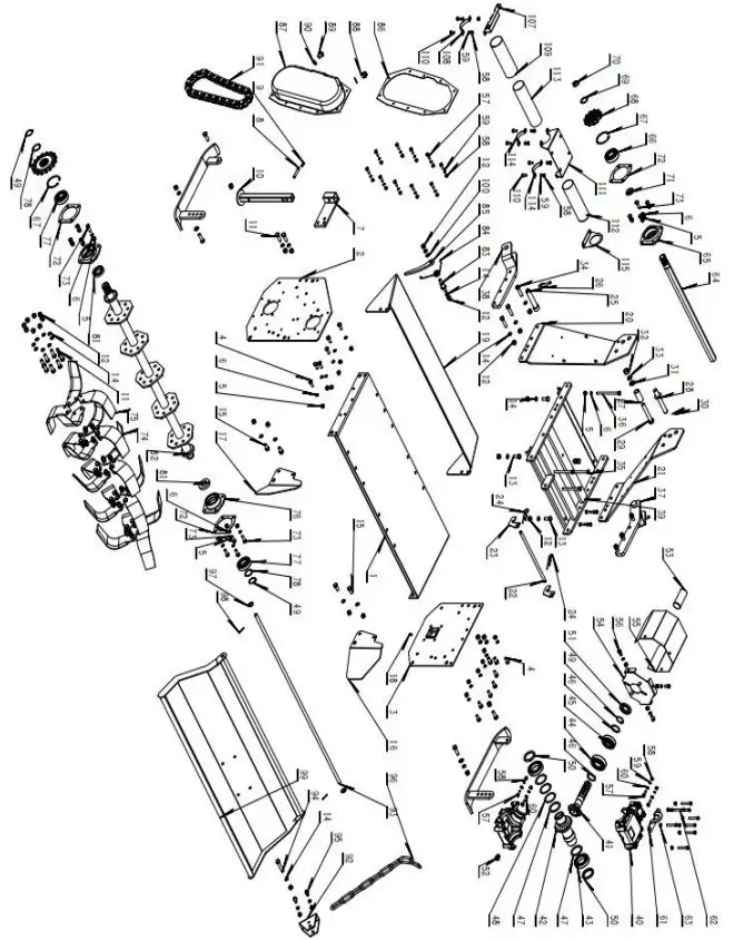
| REF | PART NO | DESCRIPTION | QTY |
|
1 | TL85.01.05 | Tiller Body TL85 | 1 |
| TL105.01.05 | Tiller Body TL105 | 1 | |
| TL115.01.05 | Tiller Body TL115 | 1 | |
| TL125.01.05 | Tiller Body TL125 | 1 | |
| 2 | TL105.01-03 | Side Panel – Left | 1 |
| 3 | TL105.01-06 | Side Panel – Right | 1 |
| 4 | GB/T 5785-2000 | Bolt kit, Bolt M10x1.25, | 12 |
| 5 | GB/T 6171-2000 | Locking Nut M10 | 33 |
| 6 | GB/T 93-1987 | 33 | |
| 7 | TL105.01.01.02 | TLWelding of Stand Leg | 1 |
| 8 | GB 882-88 | Pin Ø10 55 | 1 |
| 9 | B- Ø3 | “R” Clip 3mm | 1 |
| 10 | TL105.01.01.01 | TL Welding of Support Rod | 1 |
| 11 | GB/T 5785-2000 | Bolt kit, Bolt M12x1.25, 35 | 44 |
| 12 | GB/T 6171-2000 | Locking Nut M12x1.25 | 63 |
| 13 | GB/T 5785-2000 | Bolt kit, Bolt M12x1.25, | 4 |
| 14 | GB/T 93-1987 | Cushion 12 x 3.1 | 63 |
| 15 | GB/T 5785-2000 | Bolt kit, Bolt M12x1.25, 25 | 6 |
| 16 | TL105.01-04 | Fender – Left | 2 |
| 18 | JB / T 7940 1-1995 | Refueling Port M6 | 1 |
| 19 | TL85.01-02 | Front Frame Protective Plate-TL85 | 1 |
| TL105.01-02 | Front Frame Protective Plate- TL105 | 1 | |
| TL115.01-02 | Front Frame Protective Plate-TL115 | 1 | |
| TL125.01-02 | Front Frame Protective Plate-TL125 | 1 | |
| 20 | TL105.02-02 | Top Hitch Panel – Left | 2 |
| 22 | TL105.02-05 | Trailer Chain Shaft | 1 |
| 23 | TL105.02-06 | Fixed Block | 2 |
| 24 | “R” Clip 4mm | 2 | |
| 25 | TL105.02-07 | Hitch Pin (Lower Hitch Block) | 2 |
| 26 | Pin | 2 | |
| 27 | TW145.05-08 | Upper Suspension Sleeve | 1 |
| 28 | 03.31.007 | Ø19 Pin | 1 |
| 29 | GB/T 5785-2000 | Bolt M16*105 | 1 |
| 30 | R” Clip 3mm | 1 | |
| 31 | GB/T 97.2-1985 | Flat Cushion 16*3 | 1 |
| 32 | GB/T 6171-2000 | Nut M16*1.5 | 1 |
| 33 | GB/T 93-1987 | Bullet Cushion 16 x 4.1 | 1 |
| 34 | GB/T 5785-2000 | Bolt M12 x 1.25-50 | 6 |
| 35 | GB/T 5785-2000 | Bolt M10 x 1.25-135 | 2 |
| 36 | GB/T 5785-2000 | Bolt M10 x 1.25-140 | 2 |
| 38 | TL105.02.03 | Lower Hitch Bracket | 2 |
| 39 | TL105.02.01 | Gear Box Base Welding | 1 |
| 40 | TL105.03-01 | Gear Box | 2 |
| 41 | TL105.03-02 | Pinion Gear | 1 |
| 42 | TL105.03-03 | Large Bevel Gear | 1 |
| 43 | GB/T 276-94 | Bearing 6010 | 2 |
| 44 | GB/T 276-94 | Bearing 6307 | 1 |
| 45 | GB/T 276-94 | Bearing 6207 | 1 |
| 46 | TL105.03-05 | Bevel Gear Gasket | 2 |
| 47 | TL105.03-06 | Big Bevel Gear Gasket 1 | 2 |
| 48 | TL105.03-07 | Big Bevel Gear Gasket 2 | 3 |
| 49 | GB 894.2-86 | Elastic Baffle Type B for Shaft | 3 |
| 50 | HG4-692 | Oil Seal 50×62-7 | 2 |
| 51 | HG4-692 | Oil Seal 35×62-8 | 1 |
| 52 | G3/8A X 12 | External Hexagonal Plug with Pipe Thread | 1 |
| 53 | T10 | Axle Sleeve 34.84 | 1 |
| 54 | TL105.03.09-1 | TL Axis Protection Cover | 1 |
| 55 | TW145.17-2 | TW Axis Plate | 1 |
| 56 | GB/T 5785-2000 | Bolt M10 x 1.25-20 | 3 |
| 57 | GB/T 5785-2000 | Bolt M8*1-25 | 14 |
| 58 | GB/T 6171-2000 | Nut M8 * 1 | 22 |
| 59 | GB/T 93-1987 | Pad 8 x 2.1 | 22 |
| 60 | GB/T 97.2-1985 | Flat Mat 8 * 1.6 | 4 |
| 61 | TL105.03-08 | Lifting Lug | 1 |
| 62 | GB/T 70.1-2000 | Inside Hexagonal Cylindrical Head Screw | 8 |
| 63 | GB/T 6170-2000 | Nut M8 | 8 |
| 64 | TL85.04-01 | Second Axis-85 | 1 |
| TL105.04-01 | Second Axis-105 | 1 | |
| TL115.04-01 | Second Axis-115 | 1 | |
| TL125.04-01 | Second Axis-125 | 1 | |
| 65 | TL105.04-02 | TL Two-Axle Bearing Seat | 1 |
| 66 | GB/T 276-94 | Bearing 6306-RZ | 1 |
| 67 | GB 893.1-86 | Hole Retaining Ring 72 | 2 |
| 68 | TL105.04-03 | Driving Sprocket | 1 |
| 69 | TW145.01-04 | Second Axis Washer | 1 |
| 70 | GB/T894.1-1986 | Axis Retaining Ring 30 | 1 |
| 71 | TL105.04-05 | TL Active Sprocket Washer | 1 |
| 72 | TW145-16 | TW Two-Axis Bearing Seat Paper Cushion | 3 |
| 73 | GB/T 5785-2000 | Bolt M10 x 1.25-30 | 12 |
| 74 | TL105.06-04 | Blade | 10 |
| 76 | TL105.06-02 | TL Right Bearing Seat | 1 |
| 77 | GB/T 276-94 | Deep Groove Ball Bearing | 2 |
| 78 | TW145.14-2 | TW Tool Shaft Washer 1 | 2 |
| 79 | TL105.06-05 | Left Bearing Block | 1 |
| 80 | TL105.06-03 | Driven Sprocket | 1 |
| 81 | HG4-692 | Oil Seal | 2 |
| 82 | TL85.06.01 | Tool Shaft Welding-85 | 1 |
| TL105.06.01 | Tool Shaft Welding-105 | 1 | |
| TL115.06.01 | Tool Shaft Welding-115 | 1 | |
| TL125.06.01 | Tool Shaft Welding-125 | 1 | |
| 83 | TL105.07-1 | TL Transmission Chain Tension Shaft | 1 |
| 84 | TL105.07-2 | TL Transmission Chain Tension Spring | 1 |
| 85 | TL105.07-3 | TL Trans. Chain Tensioning Rocker Arm | 1 |
| 86 | TW145-02 | TW Side Box Cover Gasket | 1 |
| 87 | TW145.13.01 | Welding of TW Side Box Shell | 1 |
| 88 | Fuel bolt | 1 | |
| 89 | Filling and Discharging Bolts | 1 | |
| 90 | Composite Gasket 16 | 2 | |
| 91 | TL105.08-1 | Drive Chain | 1 |
| 92 | TL105.09-02 | Trailer Chain Fixed Block | 1 |
| 93 | TL85.09-03 | Drag Pin | 1 |
| TL105.09-03 | 1 | ||
| TL115.09-03 | 1 | ||
| TL125.09-03 | 1 | ||
| 94 | GB/T 5785-2000 | Bolt M12 x 1.25-60 | 1 |
| 95 | GB/T 5785-2000 | Bolt M10 x 1.25-25 | 2 |
| 96 | TW145.10-2 | Trailer Chain 8 | 1 |
| 97 | GB/T 97.2-1985 | Flat Pad 14 | 2 |
| 98 | GB/T 91-2000 | Cotter Pin | 2 |
| 99 | TL85.09.01 | Trailing Weld-85 | 1 |
| TL105.09.01 | Trailing Weld-105 | 1 | |
| TL115.09.01 | Trailing Weld-115 | 1 | |
| TL125.09.01 | Trailing Weld-125 | 1 | |
| 100 | TL105.01.07 | Welding of TL Left Anti-Wear Plate | 1 |
| 101 | TL105.01.07+ | Welding of TL Right Anti-Abrasion Plate | 1 |
| 102 | GB/T 889.2-2000 | Nylon Self-locking Nut | 2 |
| 103 | GB/T 5785-2000 | Bolt M12 x 1.25-40 | 2 |
| 104 | GB/T 97.2-1985 | Flat Cushion 12 x 2.5 | 3 |
| 105 | GB/T 5785-2000 | Bolt M8*1-30 | 2 |
| 106 | TL105.05.01-1 | TL Second-Axis Protective Cover Fixer | 1 |
| 107 | TL105.05.01-2 | TL Second-Axis Protective Cover Pipe Card | 1 |
| 108 | TL85.05.01-3 | External Diameter 68-85 | 1 |
| TL105.05.01-3 | External Diameter 68-105 | 1 | |
| TL115.05.01-3 | External Diameter 68-115 | 1 | |
| TL125.05.01-3 | External Diameter 68-125 | 1 | |
| 109 | GB/T 5785-2000 | Bolt M8*1-20 | 6 |
| 110 | TL105.05.02-1 | TL Two-Axis Shield Holder 2 | 1 |
| 111 | TL85.05.02-2 | 62 Right Inner Tube-85 | 1 |
| TL105.05.02-2 | 62 Right Inner Tube-105 | 1 | |
| TL115.05.02-2 | 62 Right Inner Tube-115 | 1 | |
| TL125.05.02-2 | 62 Right Inner Tube-125 | 1 | |
| 112 | TL85.05.02-3 | 62 Inner Tube-85 | 1 |
| TL105.05.02-3 | 62 Inner Tube-105 | 1 | |
| TL115.05.02-3 | 62 Inner Tube-115 | 1 | |
| TL125.05.02-3 | 62 Inner Tube-125 | 1 | |
| 113 | TL105.05.02-5 | TL Second-Axis Protective Cover Tubular Card | 2 |
| 114 | TL105.05.02-4 | TL Second-Axis Shield Right Tube Bracket | 1 |
PTO Shaft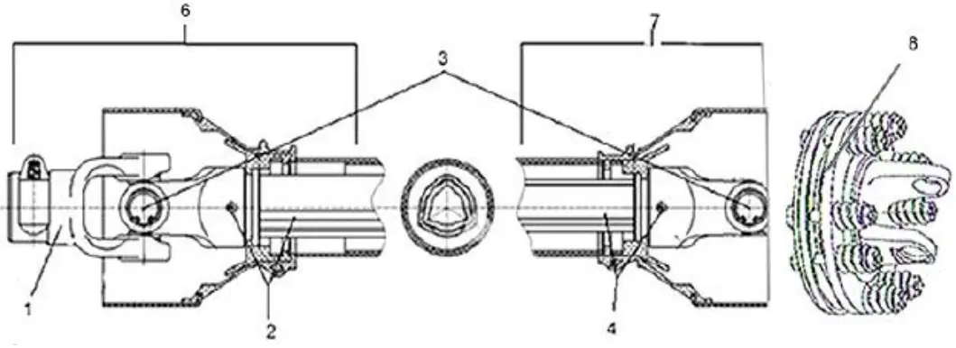
| REF | PART NO | DESCRIPTION | QTY |
| 1 | DP1075-40 | PTO Yoke – Series 40 | 1 |
| DP1075-60 | PTO Yoke – Series 60 | ||
| 2 | DP1079-40 | Female Yoke and Tube (Tractor End) – Series 40 | 1 |
| DP1079-60 | Female Yoke and Tube (Tractor End) – Series 60 | ||
| 3 | DP1076-40 | Cross and Bearings – Series 40 | 2 |
| DP1076-60 | Cross and Bearings – Series 60 | ||
| 4 | DP1078-40 | Male Yoke and Tube (Implement End) – Series 40 | 1 |
| DP1078-60 | Male Yoke and Tube (Implement End) – Series 60 | ||
| 5 | 180-510-30 | Friction Disc – 4 3/4” OD | 2-4 |
| 180-510-40 | Friction Disc – 5 1/2” OD | ||
| 6 | DP1074F-40 | Complete Female End PTO Shielding (Tractor End) – Series 20-40 | 1 |
| DP1074F-60 | Complete Female End PTO Shielding (Tractor End) – Series 60 | ||
| 7 | DP1074M-40 | Complete Male End PTO Shielding (Implement End) – Series 20-40 | 1 |
| DP1074M-60 | Complete Male End PTO Shielding (Implement End) – Series 60 | ||
| 8 | DP1098-30 | Slip Clutch Complete – 150mm Clutch (2 disc) | 1 |
| DP1098-40 | Slip Clutch Complete – 180 mm Clutch (2 disc) | ||
| DP1098-60 | Slip Clutch Complete – 180 mm Clutch (4 disc) | ||
| 9 | 147120 | Complete PTO – Series 40 – 150mm Slip Clutch | 1 |
| 147122 | Complete PTO – Series 40 – 180mm Slip Clutch | ||
| 147125 | Complete PTO – Series 60 – 200mm Slip Clutch |
Support
PHONE: 604-850-7770
FAX: 604-850-7774
TOLL FREE PHONE: 1-877-588-3311
TOLL FREE FAX: 1-800-665-7334