Braber Equipment BE-MTR2 Mini Tiller Cultivator

INTRODUCTION
IMPORTANT
This is a motorized rotary cultivator that works the soil by means of rotating tines. It is pedestrian-controlled, but not self-propelled, with a gasoline-fueled internal combustion engine to power the tines. It shall not be used for any other purpose.
For your own safety, always follow these basic precautions when using this appliance.
- Read the user Manual carefully for operating instructions. Read all instructions in this manual before use.
- DO NOT use this product for anything other than its intended purpose.
- DO NOT use attachments other than those available from the manufacturer.
- DO NOT alter this product in any manner; doing so is dangerous and will void all warranties.
- DO NOT allow children or adults weighing under 100 lbs. to operate this unit.
- DO NOT allow your body, loose clothing, drawstrings, scarves, hats or other materials to touch the power head, or tines at any time.
- DO NOT operate under the influence of drugs or alcohol.
- DO NOT continue to use this product in the event of mechanical or electrical failure.
- The tines are very sharp. Use extreme caution when cultivation or replacing the tines.
- This product produces considerable cutting force that is felt by the operator. Make sure your feet are firmly planted and the handles are firmly held while operating this product.
- During operation, the tines unit could possibly stop. Be prepared at any time to release the buttons.
- Check tines shaft screws before and after each use to make sure they are tight.
- Disconnect and insulate spark plug wire before maintenance and/or changing blades
- Do not put hands or feet near or under rotating parts
- Never operate machine in wet grass. Always be sure of your footing; keep a firm hold on the handle and walk; never run.
- Never pick up or carry the machine while the engine is running
- Keep all screws, nuts and bolts tight
| TECHNICAL DETAILS | |
| Engine type | 2-stroke |
| Engine Displacement | 51.7cc |
| Engine power | 1.3kw/7000rpm |
| Fuel tank capacity | 36 ounces |
| Mixing ratio gasoline: 0il | 30:1 |
| Tilling Width | 10″ maximum |
| Tilling depth | 10″ maximum |
| Tine speed | 256rpm |
| Weight | 14 kg |
PREFACE
The mini rotating plough machine has character of reasonable constructions, beautiful outlook, etc. For better convenient operation, please strictly complying the following items:
- Before operating the machine, please read the manual carefully, keeping the manual for reading at any moment.
- The machine was designed for garden, Not using in other.
- When machine is operation, prohibit touching the gear wheel.
In order to improve the quality, the changes of some parts which are changed according to the market will not be informed separately. Please give enough understanding.
SAFETY
Special safety precautions must be observed when working with the machine.
- Demand for protective clothing
- Clothing must be sturdy and snug-fitting;
- Wear flanged cap, wear dirt/fog-proof glasses;
- Wear Long boots or no-slippery shoes, prohibited wear slip-on shoes to operate.
- Do not operate the machine in no accordance with these
- Person without knowledge of the machine;
- Over-tired or patients;
- Drunk;
- Children.
- Avert fire
- Stop the machine when fill the fuel, prohibited fire and smoke;
- Keep away fuel from the fire.
- Preparation before operating
- Check whether the screws and nuts are loose: check whether the passage is good.
- Inspected all control rod and safe devices whether they are assembled right.
- Prohibited using the machines which have fault.
- Start-up
- Make sure there is no others in the work area;
- When the machines recoiled start, you must keep away from tines and close upon it, prevent it from moving, and make sure it is safe.
- Safe operation
- When use the machine, please keep right posture, close upon the handle;
- When operating, forbid anybody enter the work area;
- While the weather raining, please take care of the slippery ground;
- When the tines is locked, please power off the machine, start again after clean it off;
- When scarifying, please move ahead and counter-march is prohibited;
- When change the work area, stop the machine, then check whether the screws and nuts are loose.
- Examine and Repair
- Make sure the professional person maintains the machine;
- Should inspect the machine termly, if appear abnormity when operating, must stop the machine for repairing at once;
- Need for repairing or service, please contact our Super Handy customer service center by 1-866-493-0524 for assistance.
STRUCTURE
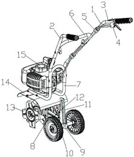
| REF | DESCRIPTION |
| 1 | Right handle |
| 2 | Left handle |
| 3 | Stop switch |
| 4 | Throttle lever assembly |
| 5 | Fasten buckle |
| 6 | Middle handle |
| 7 | Down handle |
| 8 | Back bracket |
| 9 | Wheel adjuster base |
| 10 | Wheel |
| 11 | Wheel adjuster plate |
| 12 | Depth skid |
| 13 | Blade |
| 14 | Mud guard |
| 15 | Engine |
WARNING
- DO NOT STORE ENGINE INDOORS WITH FUEL IN THE TANK. FUEL AND FUEL VAPORS ARE HIGHLY FLAMMABLE.
- NEVER MIX FUEL AND OIL DIRECTLY IN ENGINE FUEL TANK. USE ONLY NONMETAL, PORTABLE FUEL CONTAINERS APPROVED BY THE UNDERWRITER’S LABORATORY (U.L.) OR THE AMERICAN SOCIETY FOR TESTING & MATERIALS (ASTM).
- AN ADULT MUST ALWAYS HANDLE AND FILL THE ENGINE WITH FUEL.
- ALWAYS HANDLE GAS IN A WELL VENTILATED AREA, OUTDOORS, AWAY FROM FLAMES OR SPARKS.
- DO NOT START ENGINE IF FUEL IS SPILLED. WIPE OFF EXCESS FUEL AND ALLOW TO DRY. REMOVE ENGINE FROM AREA TO AVOID SPARKS.
- EVER RUN ENGINE INDOORS. EXHAUST FUMES ARE DEADLY.
- FAILURE TO FOLLOW THESE WARNINGS CAN CAUSE DAMAGE TO EQUIPMENT AND INJURY TO PERSONNEL
ASSEMBLING AND ADJUSTMENT
Figure 1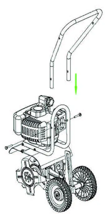
Figure 2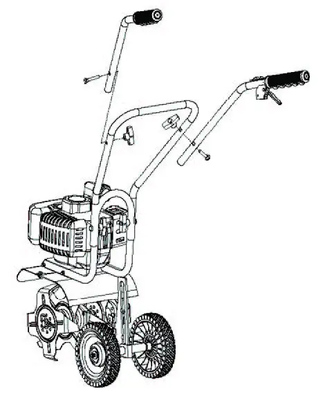
Assembly of middle and down handles. (Fig.1)
As fig 1 shows, insert the middle handle to down handle until the holes match, and then fasten the two handles by the bolts and nuts.
Assembly of left / right handle.
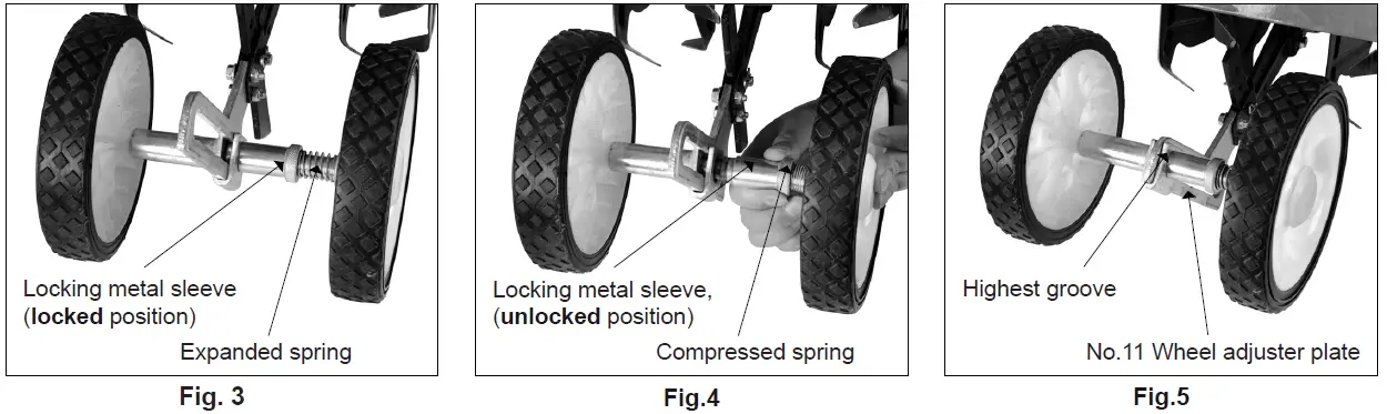
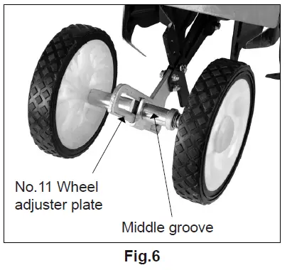
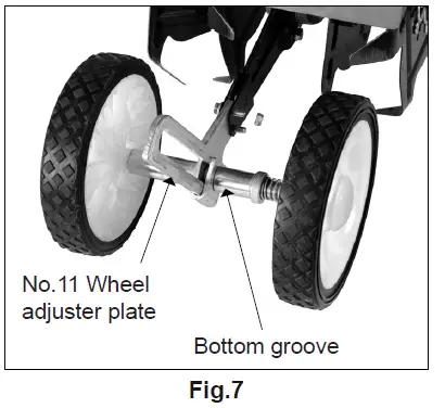
As above Fig 2. first, match the left/right handle holes to the middle handle holes, fasten the bolts and nuts. Adjusting Wheels and depth skid. There are three grooves in the wheel adjuster plate (No.11), the wheels on the cultivator can be adjusted to one of three positions. Adjust Wheels Up Or Down do as follows:
- Pull the locking metal sleeve against the spring, away from the wheel adjuster plate (No.11) until it releases from one of the three grooves in the wheel adjuster plate (No.11). Fig 3

- Slide the wheel set up or down to the desired position, and release the locking metal sleeve until it locks into desired groove in the wheel adjuster plate (No.11). wheel adjuster plate (No.11). Fig 4
- When working should put the wheels in the highest groove. Fig 5
- When not working, the wheels need putting in the middle or the bottom groove (depend on operators height). Fig 6 & Fig 7


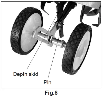
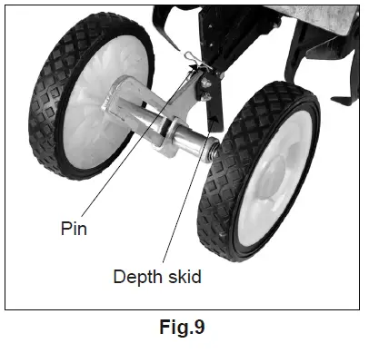
Adjust depth skid (No12), there are several holes in the depth skid, you can adjust it according to self-request. Fig 8 & Fig 9
OPERATION
WARNING
Thoroughly inspect the area where the machine is to be used and remove all foreign objects.
Your equipment can propel small objects at high-speed causing personal injury or property damage. Stay away from breakable objects, such as house windows, automobile, greenhouses, etc. Always wear safety goggles or safety glasses with side shields when operating the machine to protect your eyes from foreign objects which can be thrown from the unit. Always wear a protective hearing device. It is advisable to wear protective headgear to prevent the possibility of being struck by small flying particles, or being struck by low hanging branches, twigs, or other objects which may be unnoticed by the operator. If the equipment should start to vibrate abnormally, stop the engine, disconnect the spark plug wire and prevent it from touching the spark plug. Check immediately for cause. Vibration is generally a warning of trouble. If the noise or vibrations of the machine increase, stop immediately and perform an inspection.
Adding oil
Mixing rate between 93 # gasoline and two-stroke oil is 30:1 Attention:
- Forbid to use pure gasoline or the mixture oil rate above 30:1
- Adding fuel must be done under the instruction of the fireproofing
Start up
- Press the button of carburetor 5-6 times, until some fuel in the tube, then close the broker;
Note: If engine is in high temperature , you should put the choker on the original position. - Open the accelerograph 1/3-1/2;
- Pull the starter smoothly, after starting the engine, open choker fully.
Note:- Make sure there is nothing lock the gear wheels before starting
- When the gear blade is running, make sure the gear blade do not come up against anything or anybody.
Assignment
Strictly control the rotating speed, the free-load forward speed should be at 0.5m / sec when the rotate speed arrive at 8000-9000/min. To be ensure the quality of rotating blade, don’t touch it to other objects, such as stone.
Stopping
- Put the throttle lever at the idle speed, make the engine run 2-3 minutes;
- Turn off the stop switch.
Note: In urgent case, turn off the throttle switch, and turn off the stop switch. Keep your hands far away from rotating blade, the gear is still turning after stopping the machine.
MAINTENANCE Maintenance body
- After the machine works for one or two hours or when stopping to add oil: you must check each screw and nut on the machine to make sure they are not loosen
- Add the lube in the gear box when the machine works around 20 hours
- When the blade or gear damaged, please repair or replace at once.
Maintenance engine
- Maintenance spark plug
Keep the spark plug cleaning, the electrode gap should be moderate suitable to ensure the engine working well. The correct gap should be around 0.028in, check frequently and adjust it when the gap is too long or too short. - Maintenance the air filter
Air filter surface should be cleaned often, if the cleaner element were jammed, clean the element. Clean the filter body by gas. Drop a lie motor oil on the cleaner element, not attach it back to the inside cover until the oil dry. If the sponge is too dirty, please change a new one.
TROUBLESHOOTING
| PROBLEM | POSSIBLE CAUSES | POSSIBLE SOLUTION |
| Engine will not start | Power switch off | Flip switch to ON position |
| Spark plug wire disconnected | Connect spark plug wire to spark plug | |
| Out of fuel | Refuel | |
| Spark plug wet, faulty or improperly gapped | Clean, replace or gap spark plug | |
| Fuel line hose not positioned in bottom of gas tank | Push fuel line down into fuel in gas tank | |
| Engine runs rough, floods during operation | Dirty air filter | Clean or replace air filter |
| Choke partially engaged | Turn off choke | |
| Carburetor out of adjustment | Call customer service | |
| Engine is hard to start | Stale fuel | Drain old fuel and replace with fresh. Use gas stabilizer at end of season |
| Spark plug wire loose | Make sure spark wire is securely attached to spark plug | |
| Dirty carburetor | Clean carburetor, use gas stabilizer, new gas can | |
| Engine misses or lacks power | Clogged gas tank | Remove and clean gas tank |
| Clogged air filter | Clean or replace air filter | |
| Carburetor out of adjustment or bad | Call customer service | |
| Spark plug wet, faulty or improperly gapped | Clean, replace or gap spark plug | |
| Engine runs, then quits | Gas cap not venting | Clean or replace gas cap, check vent |
| Plugged fuel filter | Clean or replace fuel filter | |
| Carburetor out of adjustment or bad | Call customer service | |
| Engine revs too high | Carburetor out of adjustment | Call customer service |
| Tines turn at idle | Idle speed too high | Adjust idle speed lower |
| Broken clutch spring | Replace spring |
TILLER EXPLODED VIEW AND PARTS LIST
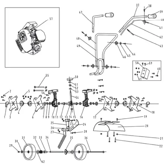
| REF | PART NO | DESCRIPTION | QTY |
| 1 | 102.107B.001 | Tear pin | 2 |
| 2 | 102.107B.002 | Bolt M6x20 | 14 |
| 3 | 102.107B.003 | 4 sided tiller blade | 1 |
| 4 | 102.107B.004 | Setting | 4 |
| 5 | 102.107B.005 | Screw M6 | 16 |
| 6 | 102.107B.003 | 4 sided tiller blade | 1 |
| 7 | 102.107B.007 | Oil seal shell | 2 |
| 8 | 102.107B.008 | Felt washer | 2 |
| 9 | 102.107B.009 | Oil seal | 2 |
| 10 | 102.107B.010 | Left crankcase | 1 |
| 11 | 102.107B.011 | Big copper cap | 2 |
| 12 | 102.107B.012 | Washer | 2 |
| 13 | 102.107B.013 | Turbo | 1 |
| 14 | 102.107B.014 | Small copper cap | 1 |
| 15 | 102.107B.015 | Tube cope | 1 |
| 16 | 102.107B.016 | Right crankcase | 1 |
| 17 | 102.107B.003 | 4 sided tiller blade | 1 |
| 18 | 102.107B.003 | 4 sided tiller blade | 1 |
| 19 | 102.107B.019 | Bolt M5x12 | 2 |
| 20 | 102.107B.020 | Protected cover | 2 |
| 21 | 102.107B.021 | Screw M5 | 5 |
| 22 | 102.107B.022 | Bolt M6x40 | 4 |
| 23 | 102.107B.023 | Bolt M6x20 | 6 |
| 24 | 102.107B.024 | Wheel | 1 |
| 25 | 102.107B.025 | Connect bat I | 1 |
| 26 | 102.107B.026 | Bolt assy | 1 |
| 27 | 102.107B.027 | Connect bat II | 1 |
| 28 | 102.107B.028 | Bolt M6x20 | 2 |
| 29 | 102.107B.029 | Screw M8 | 3 |
| 30 | 102.107B.030 | Washer 8 | 2 |
| 31 | 102.107B.031 | Wheel | 2 |
| REF | PART NO | DESCRIPTION | QTY |
| 32 | 102.107B.032 | Spring | 1 |
| 33 | 102.107B.033 | Bushing I | 1 |
| 34 | 102.107B.034 | Wheel Axle | 1 |
| 35 | 102.107B.035 | Bushing II | 1 |
| 36 | 102.107B.036 | Wheel bolt | 1 |
| 37 | 102.107B.037 | Right handle | 1 |
| 38 | 102.107B.038 | Bolt M5x30 | 3 |
| 39 | 102.107B.039 | Rubber handle Sheath | 2 |
| 40 | 102.107B.040 | Rubber gasket | 1 |
| 41 | 102.107B.041 | Throttle hand ASSY | 1 |
| 42 | 102.107B.042 | Throttle line ASSY | 1 |
| 43 | 102.107B.043 | Tube | 4 |
| 44 | 102.107B.044 | Profiled bolt | 4 |
| 45 | 102.107B.045 | Washer 8 | 8 |
| 46 | 102.107B.046 | Knob comp | 4 |
| 47 | 102.107B.047 | Left handle | 1 |
| 48 | 102.107B.048 | Machine farm I | 1 |
| 49 | 102.107B.049 | Machine farm II | 1 |
| 50 | 102.107B.050 | Knob comp | 1 |
| 51 | 102.107B.051 | Bearing | 1 |
| 52 | 102.107B.052 | Wheel bolt | 2 |
| 53 | 102.107B.053 | Paine bearing | 1 |
| 54 | 102.107B.054 | Washer | 1 |
| 55 | 102.107B.055 | Bolt M8x135 | 2 |
| 56 | 102.107B.056 | Bolt M6x8 | 2 |
| 57 | 102.107B.057 | Engine | 1 |
| 58 | 102.107B.058 | Electrical assign | 1 |
| 59 | 102.107B.059 | Bolt M6x12 | 2 |
| 60 | 102.107B.060 | Bolt M5x12 | 1 |
| 61 | 102.107B.061 | Washer 5 | 3 |
| 62 | 102.107B.062 | Washer 12 | 2 |
TILLER EXPLODED VIEW AND PARTS LIST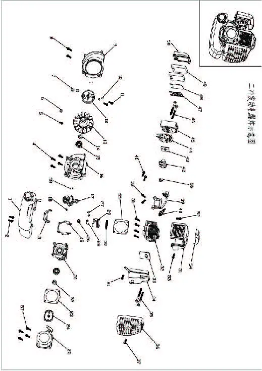
| REF | PART NUM. | DESCRIPTION | QTY |
| 1 | 102.107B.001 | Oil tank | 1 |
| 2 | 102.107B.002 | Allen screw M5*20 | 2 |
| 3 | 102.107B.003 | Oil tank bracket | 1 |
| 4 | 102.107B.004 | Allen screw M5*35 | 4 |
| 5 | 102.107B.005 | M8 nut | 1 |
| 6 | 102.107B.006 | Washer | 1 |
| 7 | 102.107B.007 | Washer | 2 |
| 8 | 102.107B.008 | Allen screw M5*20 | 2 |
| 9 | 102.107B.009 | Left cover | 1 |
| 10 | 102.107B.010 | Spring washer | 2 |
| 11 | 102.107B.011 | Step screw M8*24 | 1 |
| 12 | 102.107B.012 | Clutch | 1 |
| 13 | 102.107B.013 | Fly wheel | 1 |
| 14 | 102.107B.014 | 15*30*7 oil seal | 1 |
| 15 | 102.107B.015 | 6202 bearing | 2 |
| 16 | 102.107B.016 | Left case | 1 |
| 17 | 102.107B.017 | Crankshaft | 1 |
| 18 | 102.107B.018 | Woodruffkey | 1 |
| 19 | 102.107B.019 | Case washer | 1 |
| 20 | 102.107B.020 | Right case | 1 |
| 21 | 102.107B.021 | Allen screw M5*12 | 1 |
| 22 | 102.107B.022 | 12*22*7 oil seal | 1 |
| 23 | 102.107B.023 | Recoil starter aluminum gasket | 1 |
| 24 | 102.107B.024 | Start dial | 1 |
| 25 | 102.107B.025 | Recoil start | 1 |
| 26 | 102.107B.026 | Needle bearing | 1 |
| 27 | 102.107B.027 | Piston pin clip | 1 |
| 28 | 102.107B.028 | Piston pin | 1 |
| 29 | 102.107B.029 | Piston | 1 |
| REF | PART NUM. | DESCRIPTION | QTY |
| 30 | 102.107B.030 | Piston ring | 1 |
| 31 | 102.107B.031 | Allen screw M5*20 | 4 |
| 32 | 102.107B.032 | Cylinder | 1 |
| 33 | 102.107B.033 | Muffler gasket | 1 |
| 34 | 102.107B.034 | Muffler | 1 |
| 35 | 102.107B.035 | Allen screw M6*60 | 2 |
| 36 | 102.107B.036 | Muffler cover | 1 |
| 37 | 102.107B.037 | Allen screw M5*12 | 1 |
| 38 | 102.107B.038 | Allen screw M5*25 | 2 |
| 39 | 102.107B.039 | Ignition coil | 1 |
| 40 | 102.107B.040 | Spark plug | 1 |
| 41 | 102.107B.041 | Allen screw M5*30 | 2 |
| 42 | 102.107B.042 | Intake manifold | 1 |
| 43 | 102.107B.043 | Carburetor paper gasket | 1 |
| 44 | 102.107B.044 | Carburetor | 1 |
| 45 | 102.107B.045 | Air filter | 1 |
| 46 | 102.107B.046 | Allen screw M5*55 | 2 |
| 47 | 102.107B.047 | Air filter gasket | 1 |
| 48 | 102.107B.048 | Air filter net | 2 |
| 49 | 102.107B.049 | Air filter sponge | 1 |
| 50 | 102.107B.050 | Air filter cover | 1 |
| 51 | 102.107B.051 | Cylinder cover | 1 |
| 52 | 102.107B.052 | Allen screw M5*12 | 1 |
| 53 | 102.107B.053 | Allen screw M5*20 | 1 |
| 54 | 102.107B.054 | Cylinder cover cap | 1 |
| 55 | 102.107B.055 | Cylinder paper gasket | 1 |
| 56 | 102.107B.056 | Intake manifold paper gasket | 1 |
| 57 | 102.107B.057 | Allen screw M5*20 | 4 |
| 58 | 102.107B.058 | Locating pin | 4 |
BRABEREQ.COM
PHONE: 604-850-7770
FAX: 604-850-7774
TOLL FREE PHONE: 1-877-588-3311
TOLL FREE FAX: 1-800-665-7334


