![]()
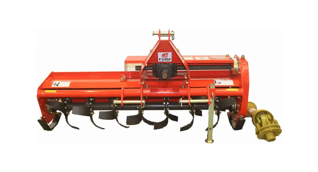
![]() FH-TL135 Rotary Garden Tiller
FH-TL135 Rotary Garden Tiller
Instruction Manual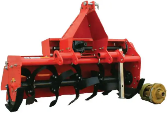
FH-TL135 Rotary Garden Tiller
Please read these instructions before using. Always grease all fittings and be sure to always check and fill with oil before operating! Retain this manual for future use.
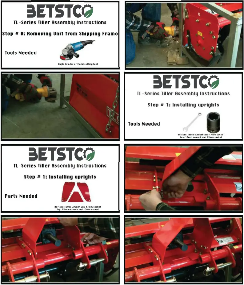
ASSEMBLY INSTRUCATION
 For any questions or concerns please contact our support department At (541)895-3083
Adjusting PTO Driveline Slip Clutch
SLIP CLUTCH IS NOT FACTORY SET
FAILURE TO ADJUST MAY RESULT IN DAMAGE TO TINES, TILLER, TRACTOR, DRIVELINE OR CLUTCH.
There are many aspects which control the needed spring tension for the slip clutch to work properly. The steps below will describe the basic adjustments of the slip clutch. This is a trial and error setup process. You may find that the tension adjustment may need to be changed each time you use your tiller based on the changing soil conditions, tractor being used, ambient temperature, and existing wear of the clutch parts or tiller tines.
WITH TRACTOR OFF AND THE KEY IN YOUR POCKET:
- Loosen all 8 bolts & nuts on the clutch until the springs are free.
- Make sure the clutch slips.
- Tighten all 8 nuts untill the nut begins to push the springs up against the flange, try first by hand, if a tool is required, do it slowly so you can observe when the springs push against the flange.
OVERTIGHTENING MAY CAUSE DAMAGE TO TINES, TILLER, TRACTOR, DRIVELINE OR CLUTCH.
- Now go test your tiller, at normal operating RPM, for no more then 6′ of trav-eled distance with the tines in the ground tilling. If you see smoke coming from the clutch or hear a loud noise from the clutch before you finish traveling 6, STOP, the clutch is slipping.
- If it doesn’t slip in the ground and you are tilling, then you are done. To be sure, check the slip clutch houseing temperature. If it is hot then the clutch is slipping. Be sure to observe the clutch as often for smoke, noise and temperature.
- If it was slipping, allow it to COOL before adjusting and attempting to till again. If you adjust before allowing it to cool, you could terminally damage any of the moving parts of the clutch, tiller or tractor, as this may cause it to be overtight-ened.
- After it has cooled, tighten the nuts 1/4 turn. Then test tiller again as noted above.
OVERTIGHTENING MAY CAUSE DAMAGE TO TINES, TILLER, TRAC-TOR, DRIVELINE OR CLUTCH. - Repeat these steps until you are comfortable that the slip clutch is not slipping under the normal operation of your tractor and the conditions in which you will be tilling.
There are many factors that may cause a need for you to adjust the clutch during operations in any given day, including soil conditions and ambient air tempera-ture. You should check the slip clutch on a regular basis for smoke, noise and build up of heat. Failure to do this may result in terminal failure of the clutch, tiller, or tractor.
OVERTIGHTENING MAY CAUSE DAMAGE TO TINES, TILLER, TRAC-TOR, DRIVELINE OR CLUTCH.
Always check the slip clutch adjustment before tilling on a different day, in different soil, with a different tractor, or a change in tem-perature.
WARNINGS
All implements with moving parts are potentially hazardous. There is no substitute Dr a cautious, safe-minded operator who recognizes the potential hazards and DIlows reasonable safety practices. The manufacturer has designed this nplement to be used with all its safety equipment properly attached to minimize he chance of accidents.
BEFORE YOU START!!
Read the safety messages on the implement and shown in your manual. Observe he rules of safety and common sense!
A SAFETY ALERT SYMBOL IDENTIFIES IMPORTANT SAFETY WARNING ESSAGES. CAREFULLY READ EACH WARNING MESSAGE THAT OLLOWS. FAILURE TO UNDERSTAND AND OBEY A SAFETY WARNING, OR RECOGNIZE A SAFETY HAZARD, COULD RESULT IN AN INJURY OR EA11-1 TO YOU OR OTHERS AROUND YOU. THE OPERATOR IS ILTIMATELY RESPONSIBLE FOR THE SAFETY OF HIMSELF, AS WELL AS 11-IERS, IN THE OPERATING AREA OF THE ROTARY TILLER INDERSTAND SIGNAL WORDS DANGER and WARNING safety signs are located near the specific hazard.
CAUTION safety signs list general precautions.
The safety-alert symbol is also ised in this manual to call attention to safety messages.
Important Safety Information!
Vorking with unfamiliar equipment can lead to careless injuries. Read this nanual, and the manual for your tractor, before assembly or operating, to icquaint yourself with the machines. It is the implement owner’s responsibility, if his machine is used by any person other than yourself, is loaned or rented, to nake certain that the operator, prior to operating:
- Reads and understands the operator’s manuals.
- Is instructed in safe and proper use.
- The use of this equipment is subject to certain hazards which cannot be protected against by mechanical means or product design.
- All operators of this equipment must read and understand this entire manual, paying particular attention to safety and operating instructions, prior to using. If there is something in this manual you do not understand, ask your supervisor, or your dealer, to explain it to you.
Most accidents occur because of neglect or carelessness. Keep all helpers and iystanders twenty-five feet (25′) from an operating rotary tiller. Only properly rained people should operate this machine. It is recommended the tractor be quipped with a Rollover Protection System (ROPS) and a seat belt that is used. Always stop the tractor, set brake, shut off the tractor engine and remove the ractor key, and lower implement to the ground before dismounting tractor. Never save equipment unattended with the tractor running. Please remember it is important that you read and heed the safety signs on the otary tiller, and the safety rules set forth. Clean or replace all safety signs if they cannot be clearly read and understood. They are there for your safety as well as he safety of others. The safe use of this machine is strictly up to you, the operator.
SAFETY PRECAUTIONS
MOST ACCIDENTS OCCUR BECAUSE OF NEGLECT OR CARELESS NESS.
AVOID NEEDLESS ACCIDENTS BY FOLLOWING ALL OF THE SAFETY PRECAUTIONS LISTED BELOW.
- Machinery should be operated only by those who are responsible and are authorized to do so. Stop the engine, lower all equipment, lock the brakes, and remove the ignition key before dismounting from the tractor.
- Never stand between tractor and implement while tractor is being backed to hitch. Loose fitting clothing should not be worn, to avoid catching on various parts.
- Detach implement in area where children normally do not play.
- When performing adjustments or maintenance on an implement, first lower it to the ground or block it securely at a workable height. Only a qualified operator should be permitted on tractor when in operation; no riders allowed. Make certain everyone is in the clear before starting tractor or raising or lowering equipment. Operate the tractor and implement only while seated in the driver’s seat. Reduce speed when transporting mounted implements to avoid bouncing and momentary loss of steering control.
- A heavy load can cause instability of the tractor.
- Use extreme care during road travel. Slow down on turns and watch out for bumps. Tractor may need front counter weights to counter balance the weight of the implement.
- Reduce speed on hillsides or curves so there is no danger of tipping.
- Avoid driving too close to the edge of ditches or creeks.
- Do not transport implement on public roads without reflectors and slow moving vehicle emblem in daylight and with approved warning lights at night and other periods of poor visibility.
- Due to the width of some implements, use extra caution on highways, farm roads, and when approaching gates.
- Always be sure the implement is in the proper position for transport.
- Keep alert and watch the front as well as the rear when working with the implement.
WHEN ORDERING REPAIR PARTS, ALWAYS GIVE THE FOLLOWING INFORMATION:
- PART NUMBER
- PART DESCRIPTION
- MODEL NUMBER
- NAME OF ITEM
Safety Information
- All equipment is potentially hazardous. There is no substitute for a cautious, safe-minded operator who recognizes potential hazards and follows reasonable safety practices.
- When the use of hand tools is required to perform any part of assembly, installation, adjustment, maintaining, repairing, removal, or moving the implement, be sure the tools used are designed and recommended by the tool manufacturer for that specific task.
- Personal protection equipment including safety glasses, safety shoes, and gloves are recommended during assembly, installation, operation, adjustment, maintaining, repairing, removal, or moving the rotary tiller.
- Always use two people to handle heavy, unwieldy components during assembly, installation, removal, or moving the rotary tiller.
- Never place any part of your body where it would be in danger if movement should occur during assembly, installation, operation, maintaining, repairing, removal, or moving the implement.
- Never place yourself between the tractor and implement while implement is in operation.
- Do not work under a raised implement unless it is securely blocked or held in position. Do not depend on the tractor hydraulic system to hold the implement in place.
- A heavy load can cause instability of the tractor. Use extreme care during travel. Slow down on turns and watch out for bumps. The tractor may need front counter-weights to counter-balance the weight of the implement.
- Never use alcoholic beverages or drugs which can hinder alertness or coordination while operating this equipment. Consult your doctor about operating this machine while taking prescription medications.
- Do not allow others to ride on the tractor with an operator. Riders are subject to injury such as being struck by foreign objects or being thrown off. Riders obstruct the operator’s view resulting in unsafe operation. Never allow anyone to ride on the implement!
- Before you operate the rotary tiller, check over all pins, bolts and connections to be sure all are securely in place. Replace any damaged or worn parts immediately.
- Do not allow anyone who is not familiar with the safety rules and operation instructions to use this rotary tiller. Never allow children to operate or be around equipment.
- Use stabilizer bars, adjustable sway chains, or sway blocks on your tractor lift arms to keep the rotary tiller from swinging side to side. Adjust as tightly as practical for best performance.
- Keep alert and watch the front as well as the rear when working with the implement.
- When maneuvering close to buildings or passing through narrow areas, be sure to allow sufficient clearance for the implement.
- Do not operate close to ditches or creeks. Slow down when operating over rough ground.
- Always be sure the implement is in the fully raised position when in transport.
- When adjusting the assembly, be sure that your feet are never under the rotary tiller.
- Be careful to avoid catching the rotary tiller on stumps or other immovable objects.
- Use care when working on slopes.
- Avoid excessive speed during operation.
- Make adjustments only when the implement is attached to the tractor.
- Do not use the rotary tiller in a reverse position, use extra care. Do not ram rotary tiller into piles of dirt. Tractor lift arms and the rotary tiller are not built to take high impact loads in this position. Ramming backwards can also dislodge operator from seat and/or tractor controls, resulting in possible serious injury or death.
- Always ease the tractor into the load. It may be necessary to reposition and take less “bite” on the material to move it safely.
- Watch for and avoid hidden obstructions, i.e., buried pipes, rocks, concrete piers, uneven concrete slabs, stumps, etc., when operating.
Farmer – Helper Series Chain Driven Rotary Tillers
| SPEC | FH-TL085 | FH-TL095 | FH-TL105 | FH-TL125 | FH-TL135 |
| Standard Tine Rotation | Yes | Yes | Yes | Yes | Yes |
| Working Width | 33″ | 37″ | 41″ | 48″ | 53″ |
| Overall Width | 39″ | 43″ | 47″ | 54″ | 60″ |
| Min.- Max. HP | 12 HP – 40 HP | 14 HP – 40 HP | 16 HP – 40 HP | 18 HP-40 HP | 20 HP – 40 HP |
| 3 Point Hitch | Cat I | Cat I | Cat I | Cat I | Cat I |
| Offsetable Distance from Center | 11″ | 12″ | 14″ | 16″ | 18″ |
| Gear Box Maximum PTO HP | 35 HP | 35 HP | 35 HP | 35 HP | 35 HP |
| Number of Flanges | 4 | 4 | 5 | 7 | 7 |
| Number of L shaped Tines | 16 | 16 | 20 | 28 | 28 |
| Maintenance Free Oil Bath Transmission | Auto Adjusting #60 Chain Drive | Auto Adjusting #60 Chain Drive | Auto Adjusting Twin #60 Chain Drive | Auto Adjusting Twin #60 Chain Drive | Auto Adjusting Twin #60 Chain Drive |
| Double Walled Housing | 114″ | 114″ | 114″ | 1/4″ | 114″ |
| Rotor Swing Dia, | 14″ | 14″ | 14″ | 14″ | 14″ |
| Adjustable Tilling Depth | 2″-6″ | 2n- 6″ | 2″- 6″ | 2″- 6″ | 2″- 6″ |
| PTO Slip Clutch | Yes | Yes | Yes | Yes | Yes |
| 540 rpm PTO Drive Line | Series 41-318″ 6 Spline Quick Connect Slip Clutch | Series 4 1-3/8°6 Spline Quick Connect Slip Clutch | Series 41-318″ 6 Spline Quick Connect Slip Clutch | Series 41-318″ 6 Spline Quick Connect Slip Clutch | Series 41-318″ 6 Spline Quick Connect Slip Clutch |
| Warranty | 2 Year | 2 Year | 2 Year | 2 Year | 2 Year |
| Weight | 310 lbs | 330 lbs | 350 lbs | 400 lbs | 430 lbs |
| Crated Weight | 325 lbs | 350 lbs | 375 lbs | 4251bs | 460 lbs |
INSTRUCTIONS
TRACTOR REQUIREMENTS AND PREPARATION
The rotary tiller will fit most Category 1 tractors equipped with a standard 3-point hitch. The pins need to be installed to the inside of the 3-point frame for use with Category 1 tractors. The rotary tiller is for use on Category 1 tractors up to 45 horsepower in size.
- Check the tractor’s 3-point hydraulic lift system.
- It should operate up and down smoothly and hold its position when set.
- Refer to your tractor owner’s manual or dealer for any adjustments necessary to put the 3-point hydraulic lift system in good working order.
- Tractor should be equipped with stabilizer bars, adjustable sway chains, or sway blocks to keep the implement from swinging side to side.
- Smaller size tractors may need front counter weights to counter-balance the weight of the implement.
- It is recommended that the tractor be equipped with a Rollover Protection System (ROPS) and a seat belt that is used.
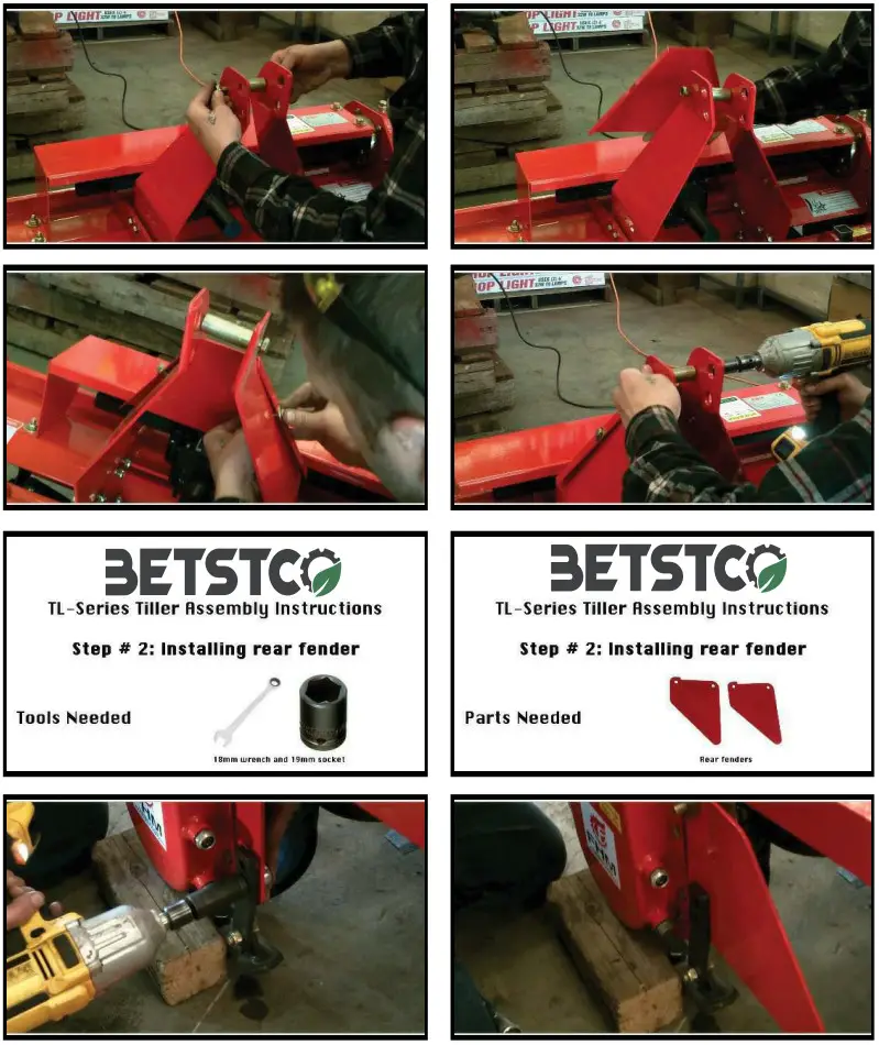
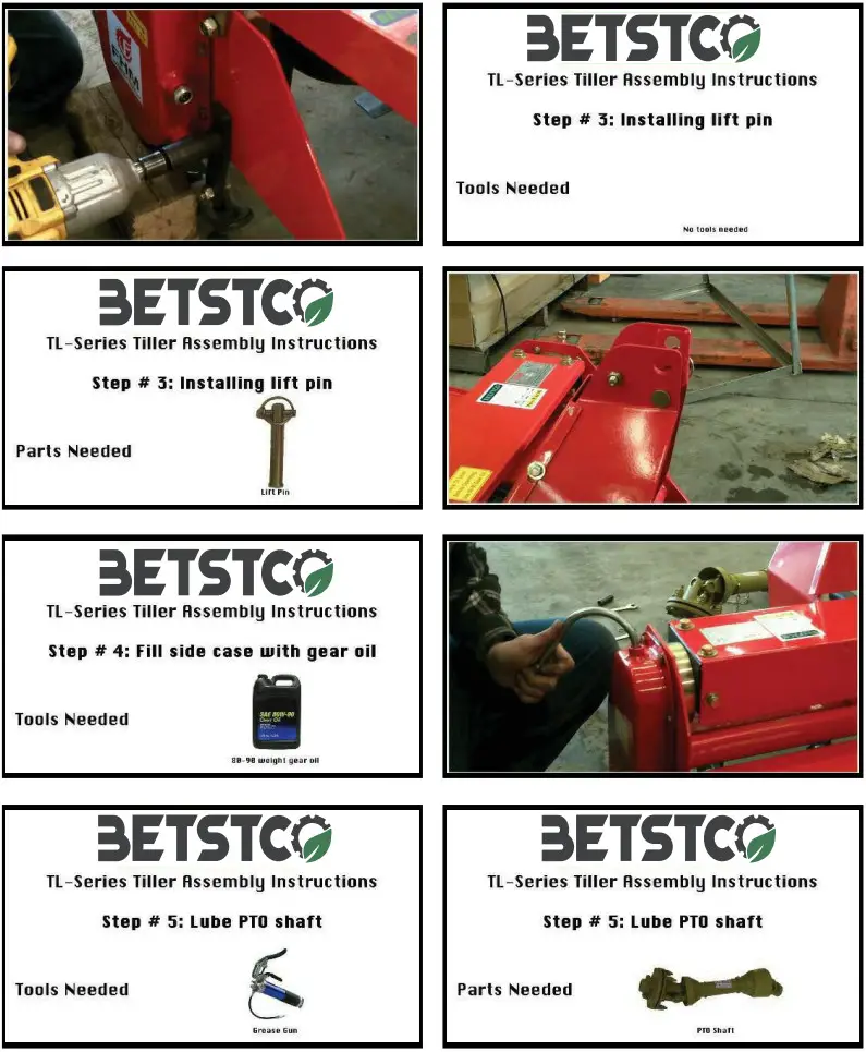
ASSEMBLY AND MOUNTING (See Pictures Below)
- Attach the 3Pt frame plate, to the supporting plate.
- DO NOT tighten hardware.
- Attach the rear 3Pt frame plate.
- A-frame should be positioned to the frame now tighten the hardware.
- Fill gear box and side chain case with 80-90 gear oil. To oil fill point.
- Grease end shaft of tiller and PTO U-Joints will lithium based grease.
- Attach rear float chain.
- Attach rotary tiller hitch frame to tractor 3-point hitch using a 3A lynch (Cat 1) top link pin and lynch pins.
- Attach PTO Driveline.
- Adjust offset to desired position, do this while tiller is lifted slightly off ground.
- Your rear mounted tiller is now assembled and mounted on your tractor. It is ready to go to work for you.
- Do not attach storage stand until you have completed your work and ready to store the tiller.
NOTE: Always use the tractor anti-sway bars, blocks, or chains to prevent tiller side-sway.
CAUTION!
Be sure your tractor is in good condition. Read all the safety precautions and make sure all tractor operators are familiar with the safety rules of operation. Please work, drive, play, and live each day with care and concern for your safety and that of your family and fellow citizens. 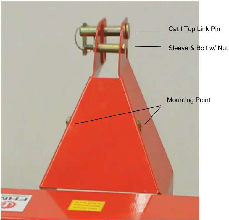 Mounting Plates, Top Link Pin, Sleeve & Bolt
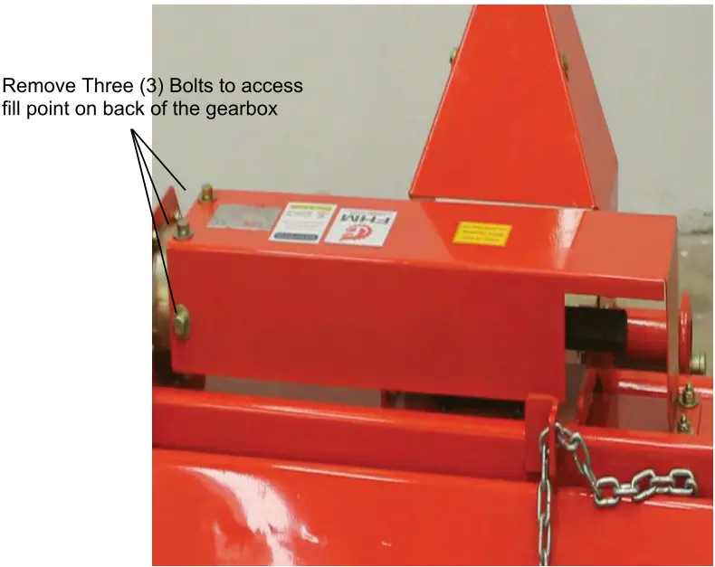 Gear Box Oil Ports & Rear Float Chain
 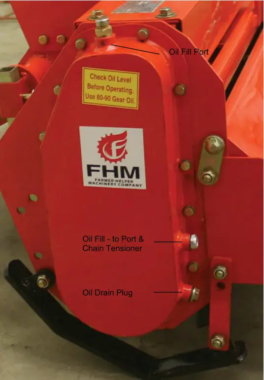 Chain Case Oil Ports
 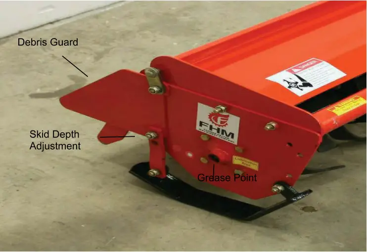 Side Grease Point and Skid Depth Adjustment
Debris Guard is no Longer available for this product 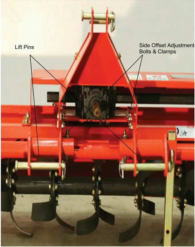 Offset Adjustment Bolts & Clamps, Lift Pins, and Removable Storage
Stand
| Torque Values Chart | ||||||||||||||
| Bolt Head Identification | Bolt Head Identification | |||||||||||||
| in-tni¹ | N • m | ft-Ih³ | N • m | ft.lh | N • m | ft-lh | mm × nitch | N • m | ft-lh | N • m | ft-Ib | N • m | ft-lb | |
| 1/4″- 20 | T4 | 6. | 11 | 8 | 16 | 12 | M 5 × 0.8 | 4 | 3 | 6 | 5 | 9 | 7 | |
| 1/4″- 28 | 9. | 6 | 13 | 10 | 18 | 14 | M 6 × 1 | 7 | 5 | 11 | 8 | 15 | 11 | |
| 5/16″ – 18 | 15 | 11 | 24 | 17 | 33 | 25 | M 8 × 1.25 | 17 | 12 | 26 | 19 | 36 | 27 | |
| 5/16″ – 24 | 17 | 13 | 26 | 19 | 37 | 27 | M 8 × 1 | 18 | 13 | 28 | 21 | 39 | 29 | |
| 3/8″ – 16 | 27 | 20 | 42 | 31 | 59 | 44 | M10 × 1.5 | 33 | 24 | 52 | 39 | 72 | 53 | |
| 3/8″ -24 | 31 | 22 | 47 | 35 | 67 | 49 | M10 × 0.75 | 39 | 29 | 61 | 45 | 85 | 62 | |
| 7/16″ – 14 | 43 | 32 | 67 | 49 | 95 | 70 | M12 × 1.75 | 58 | 42 | 91 | 67 | 125 | 93 | |
| 7/16″ – 20 | 49 | 36 | 75 | 55 | 105 | 78 | M12 × 1.5 | 60 | 44 | 95 | 70 | 130 | 97 | |
| 1/2″ – 13 | 66 | 49 | 105 | 76 | 145 | 105 | M12 × 1 | 90 | 66 | 105 | 77 | 145 | 105 | |
| 1/2″ -20 | 75 | 55 | 115 | 85 | 165 | 120 | M14 × 2 | 92 | 68 | 145 | 105 | 200 | 150 | |
| 9/16″ – 12 | 95 | 70 | 150 | 110 | 210 | 155 | M14 × 1.5 | 99 | 73 | 155 | 115 | 215 | 160 | |
| 9/16″ – 18 | 105 | 79 | 165 | 120 | 235 | 170 | M16 × 2 | 145 | 105 | 225 | 165 | 315 | 230 | |
| 5/8″ – 11 | 130 | 97 | 205 | 150 | 285 | 210 | M16 × 1.5 | 155 | 115 | 240 | 180 | 335 | 245 | |
| 5/8″ -18 | 150 | 110 | 230 | 170 | 325 | 240 | M18 × 2.5 | 195 | 145 | 310 | 230 | 405 | 300 | |
| 3/4″ – 10 | 235 | 170 | 360 | 265 | 510 | 375 | M18 × 1.5 | 220 | 165 | 350 | 260 | 485 | 355 | |
| 3/4″- 16 | 260 | 190 | 405 | 295 | 570 | 420 | M20 × 2.5 | 280 | 205 | 440 | 325 | 310 | 450 | |
| 7/8″ – 9 | 225 | 165 | 585 | 430 | 820 | 605 | M20 × 1.5 | 310 | 230 | 650 | 480 | 900 | 665 | |
| 7/8″ -14 | 250 | 185 | 640 | 475 | 905 | 670 | M24 × 3 | 480 | 355 | 760 | 560 | 1050 | 780 | |
| 1″ – 8 | 340 | 250 | 875 | 645 | 1230 | 910 | M24 × 2 | 525 | 390 | 830 | 610 | 1150 | 845 | |
| 1″ – 12 | 370 | 275 | 955 | 705 | 1350 | 995 | M30 × 3.5 | 960 | 705 | 1510 | 1120 | 2100 | 1550 | |
| 1-1/8″ – 7 | 480 | 355 | 1080 | 795 | 1750 | 1290 | M30 × 2 | 1060 | 785 | 1680 | 1240 | 2320 | 1710 | |
| 1 1/8″ – 12 | 540 | 395 | 1210 | 890 | 1960 | 1440 | M36 × 3.5 | 1730 | 1270 | 2650 | 1950 | 3660 | 2700 | |
| 1 1/4″ – 7 | 680 | 500 | 1520 | 1120 | .2460 | 1820 | M36 × 2 | 1880 | 1380 | ‘960 2190 | 41003220 | |||
| 1 1/4″ – 12 | 750 | 555 | 1680 | 1240 | 2730 | 2010 | ¹in-tpi = nominal thread diameter in inches-threads per in. ²NV m = newton-meters ³ft-lb= foot pounds ⁴MM x pith= nominal thread diameter in millimeters x thread pith | |||||||
| 1 3/8 – 6 | 890 | 655 | 1990 | 1470 | 3230 | 2380 | ||||||||
| 1 3/8″ – 12 | 1010 | 745 | 2270 | 1670 | 3680 | 2710 | ||||||||
| 1 1/2″ – 6 | 1180 | 870 | 2640 | 1950 | 4290 | 3160 | ||||||||
| 1 1/2″ – 12 | 1330 | 980 | 9970 | 9190 | 4870 | 3560 | ||||||||
| Torque tolerance + 0% – 15% of torquing values. Unless otherwise spedfied use torque values listed above. | ||||||||||||||
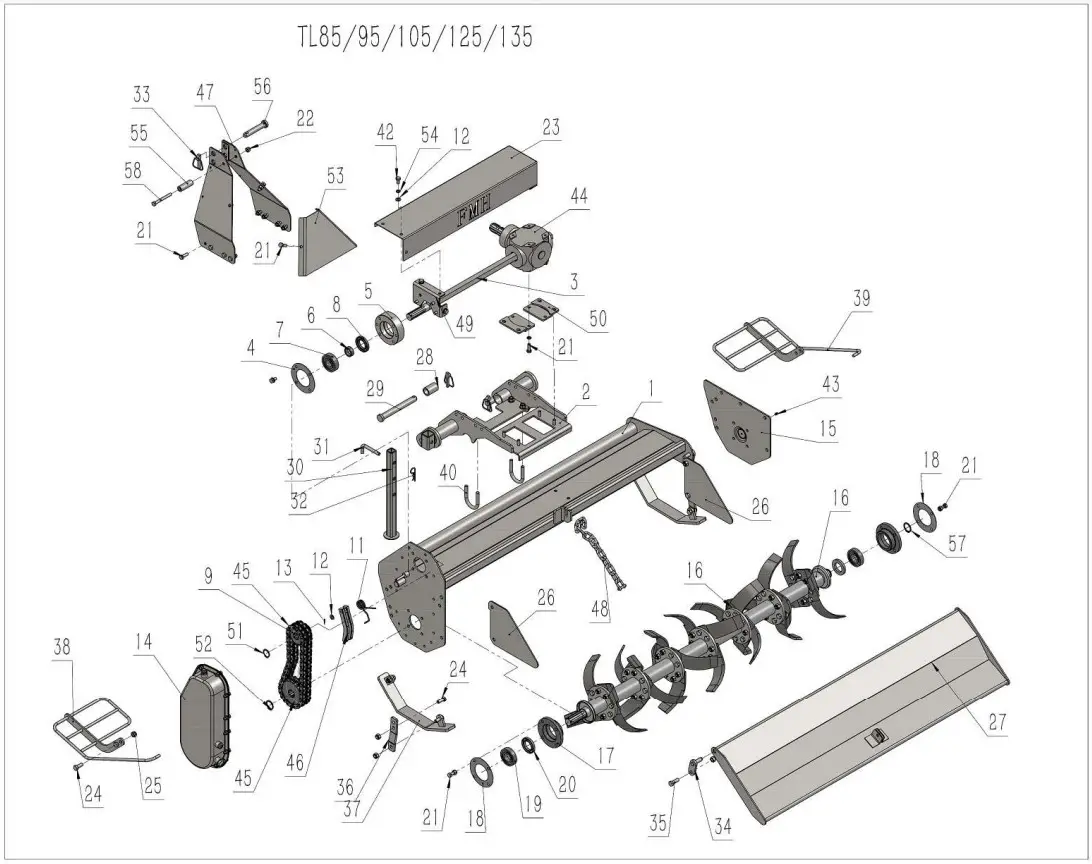 FARMER-HELPER PARTLIST TL125.001
| REF. | DWG NO. | DESCRIPTION | QTY | REMARKS |
| 1 | TL125.012 | Cover weldment | 1 | |
| 2 | TL125.013 | Side Shift Frame Weldment | 1 | |
| 3 | TL125.105 | Axle | 1 | |
| 4 | TL125.108 | Paper Wafiher for Upper Bearing Seat | 1 | |
| 5 | TL125.107 | Upper Bearing Seat | 1 | Q235-A |
| 6 | TL125.106 | Bush | 1 | 45 |
| 7 | GB276-306 | Bearing 306 | 1 | |
| 8 | GB13871-38x65x8 | Oil Seal FB38x65x8 | 1 | |
| 9 | TL125.109 | Small Sprocket Wheel | 1 | |
| 10 | TL125.110 | Big Sprocket Wheel | 1 | |
| 11 | TL125.116 | Torsional Spring | 1 | |
| 12 | GB97.1-10 | Plain Wahser 10 | 12 | |
| 13 | GB91-2×16 | Cotter Pin 2×16 | 1 | |
| 14 | TL125.003 | Chain Cover Assembly | 1 | |
| 15 | TL125.024 | Right Plate Weldment | 1 | |
| 16 | TL125.002 | Blade Axle | 1 | |
| 17 | TL125.111 | Lower Bearing Seat | 2 | HT250 |
| 18 | TL125.112 | Paper Washer for Lower Bearing Seat | 2 | |
| 19 | GB276-207 | Bearing 207 | 2 | |
| 20 | GB13871-40x65x8 | Oil Seal FB40x65x8 | 2 | |
| 21 | GB5783-M10x30 | Bolt M10x30 | 22 | |
| 22 | GB889.1-M10 | Lock Nut M10 | 21 | |
| 23 | TL125.104 | Protection Cover For Axle | 1 | |
| 24 | GB5783-M12x30 | Bolt M12x30 | 11 | |
| 25 | GB889.1-M12 | Lock Nut M12 | 18 | |
| 26 | TL125.103 | Side Plate | 2 | | |
| 27 | TL125.019 | Rear Plate | 1 | |
| 28 | EFGC125.108 | Bush for Hanging Pin | 2 | |
| 29 | EFGC125.109 | Lower Hanging Pin | 2 | |
| 30 | TL125.014 | Support Leg | 1 | |
| 31 | 1GN135.00.107 | Pin for Support Leg | 1 | |
| 32 | RP-3.2 | RPin3.2 | 1 | |
| 33 | LP-12 | Lock Pin 12 | 3 | |
| 34 | TL125.021 | Weldment for Rear Plate Pin | 2 | |
| 35 | GB5783-M12x35 | Bolt M12x35 | 3 | |
| 36 | TL125.102 | Connection Plate for Skid | 2 | |
| 37 | TL125.017 | Skid | 2 | |
| 38 | TL125.015 | Left Guard Bar | 1 | |
| 39 | TL125.016 | Right Gruard Bar | 1 | |
| 40 | TL125.117 | Lock Bolt | 2 | |
| 41 | GB97.1-12 | Plain Wahser 12 | 4 | |
| 42 | GB5783-M10x20 | Bolt M10x20 | 13 | |
| 43 | GB1152-M6 | Grease Nipple M6 | 1 | |
| 44 | XH23.146).12W | Gearbox Assembly | 1 | |
| 45 | GB1243.1-12A-2-284 | Chain 12A-2-284 | 1 | |
| 46 | TL125.026 | Tension Bar Weldment | 1 | |
| 47 | TL125.011 | Hanging Weldment | 1 | |
| 48 | TL125.020 | Chain | 1 | |
| 49 | TL125.022 | Connection Seat | 1 | |
| 50 | TL125.025 | Gearbox Seat | 2 | |
| 51 | GB894.1-30 | Circlip For Axle | 1 | 65Mn |
| 52 | GB894.1-34 | Circlip For Axle | 1 | 65Mn |
| 53 | TL125.119 | Plate For Hanging Weldment | 1 | |
| 54 | GB93-10 | Spring Washer 10 | 15 | |
| 55 | TL125.118 | Bush for Hanging Pin | 1 | Q235-A |
| 56 | EFGC125.123 | Upper Hanging Pin | 1 | |
| 57 | GB894.1-35 | Circlip 35 For Axle | 1 | |
| 58 | GB5782-M10x90 | Bolt M10x90 | 1 |
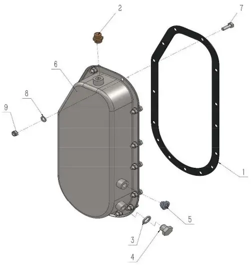
FARMER-HELPER PARTLIST TL125.003
| REF. | DWG NO. | DESCRIPTION | Qry | REMARKS |
| 1 | TL125.101 | Rubber Seal | 1 | |
| 2 | VENT G3-8 | Venting Bolt G3/8 | 1 | |
| 3 | 1BZQ4454-3-8 | Seal 3/8 | 1 | |
| 4 | 1BZQ4451-G3-8 | Plug Screw G3/8 | 1 | |
| 5 | YB-G3-8 | Oil Leveler | 1 | |
| 6 | TL125.018 | Chain Cover | 1 | |
| 7 | GB5783-M8x25 | Bolt M8x25 | 15 | |
| 8 | GB97.1-8 | Plain Washer 8 | 15 | |
| 9 | GB889.1-M8 | Lock Nut M8 | 15 |
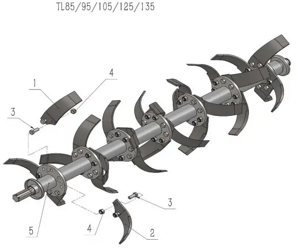
 FARMER-HELPER PARTLIST TL125.002
| REF. | DWG NO. | DESCRIPTION | QTY | REMARKS |
| 1 | TL125.114 | Right Tine | 14 | 60Si2Mn |
| 2 | TL125.113 | Left Tine | 14 | 605i2Mn |
| 3 | GB5783-M12x30 | Bolt M12x30 | 70 | |
| 4 | GB889.1-M12 | Lock Nut M12 | 70 | |
| 5 | TL125.023 | Blade Axle | 1 |
![]()
Parts Request Form
E-mail [email protected]
Name: ————-
Address: ————-
City State Zip: ————-
Phone: ————-
E-mail: ————-
Model Number: ————-
Serial Number: ————-
Purchased From: ————-
Purchase Date: ————-
| Item No. | Description | Qty | Price | Amount |
Comments:
FARMER-HELPER
Limited Warranty
Unless otherwise stated on purchase invoice, Betstco warrants to original Purchaser that Farmer-Helper products are free from major deffects in material under normal use and service for a period of 90 Days from the date the product is purchased or shipped, whichever is later. Commercial use 90 days. Use at address that is not yours, is considered commercial use. Consumable, Expendalble, Wear Items (Rubber plastic parts, hydraulic hoses, belts, tires, cables, blades, tines, wedges, teeth, tiups, chains, pins, brushes, filters, etc) and cracked hydraulic pumps, bent or broken cylinder rods are not covered under this warranty. Warranty does not cover items that have been modified, damaged by abuse or usage not in accordance with design or maintenance.
Betstco obligation under this warranty is to repair or replace defective upon approval by; Betstco, 83371 Melton Rd. N, Creswell OR 97426 that Warranty Claim is valid. Product shall be returned upon request of Betstco. Transportation charges to be prepaid by user.
Gasoline or diesel engines used to powered Farmer-Helper products are covered by the warranty of the appropriate engine manufacturean Purchaser must look to the engine manufacture for all issues relating to engine operation.
Betstco assumes no responsibility for outside labor.
PERMISSABLE BY APPLICABLE LAW, BETSTCO HEREBY DISCLAIMS ALL WARRANTIES OF ANY KIND, EITHER EXPRESS OR IMPLIED, INCLUDING, ANY IMPLIED WARRANTIES WITH RESPECT TO THE PRODUCT PURCHASED, WITHOUT LIMITING THE GENERALITY OF THE FOREGOING, BETSTCO HEREBY EXPRESSLY DISCLAIMS ALL LIABILITY FOR PRODUCT DEFECT OR FAILURE, CLAIMS THAT ARE DUE TO NORMAL WEAR, PRODUCT MISUSE, ABUSE, PRODUCT MODIFICATION, IMPROPER PRODUCT SELECTION, NON-COMPLIANCE WITH ANY CODES, OR MISAPPROPRIATION. BETSTCO MAKES NO WARRANTIES TO THOSE DEFINED AS “CONSUMERS” IN THE MAGNUSON-MOSS WARRANTY FEDERAL TRADE COMMISION IMPROVEMENTS ACT. THE FOREGOING EXCLUSION OF IMPLIED WARRANTIES DO NOT APPLY TO THE EXTENT PROHIBITED BY LAW. PLEASE REFER TO YOUR LOCAL LAWS FOR ANY SUCH PROHIBITIONS.
THERE SHALL BE NO LIABILITY FOR PRODUCT LIABILITY OR LIABILITY ON THE PART OF BETSTCO FOR ANY GENERAL SPECIAL OR CONSEQUENTIAL DAMAGES ARISING OUT OF THE SALE OR USE OF ANY PRODUCTS SOLD BY BETSTCO OR AN AGENT THEREOF, BETSTCO MAKES NO WARRANTIES, EXPRESS OR IMPLIED, (INCLUDING, BUT NOT LIMITED TO, ANY WARRANTY OF MERCHANTABILITY OR FITNESS OF THE PRODUCTS FOR ANY PURPOSE) WITH RESPECT TO THE PRODUCTS COVERED BY THIS AGREEMENT EXCEPT AS IN THIS PARAGRAPH OTHERWISE EXPRESSLY PROVIDED.
THIS IS THE SOLE AND ONLY WARRANTY OF VALUE-LEADER PRODUCTS, NO OTHER WARRANTY IS APPLICABLE, EITHE EXPRESSED OR IMPLIED, IN FACT BY LAW.
This warranty shall not be interpreted to render Betstco, or any authorized agent liable for injury or damages of any kind or nature, direct, consequential, or contingent, to a person or property.
The sole and only remedy in regard to any defective product shall be the repair or replacement thereof as herein provided, Betstco, agent(s) of Betstco shall not be liable for any consequential, special, incidental or punitive damages resulting from or caused by any such defects Betstco reserves the rights to make improvements in design or changes in specifacations at any time, without incurring any obligations to owners of the units previously sold.
WARRANTY VOID IF REGISTRATION IS NOT RECEIVED OR RECORDED ONLINE WITHIN 30 DAYS OF PURCHASE DATE OR SHIP DATE, WHICHEVER IS LATER.
ITEM: ——— MODEL# ——— PURCHASE DATE: ——-/—–/—–
PURCHASED FROM: —————- GIFT INV# ORDER# —————-
OWNER NAME: —————- SERIAL # —————-
OWNER ADDRESS: —————-
CITY: ————- COUNTY: ————- ST: ———— ZIP: ———-
PHONE: —————-
EMAIL: —————-
ACCEPTANCE OF RESPONSIBILITY:
I (PURCHASER) HAVE READ OPERATORS MANUAL AND LIMITED WARRANTY OR SOMEONE HAS READ/AND EXPLAINED ALL INSTRUCTIONS TO ME.
I UNDERSTAND THIS WARRANTY DOES NOT COVER ANY LABOR AND THAT ALL DISPUTES WILL BE SETTLED BY BINDING ARBITRATION. BINDING ARBITRATION IS CONDUCTED BY THE BETTER BUSINESS BUREAU (BBB) LOCATED AT 4004 SW KRUSE WAY PLACE ST 375 LAKE OSWEGO OR 97035 OR THE CURRENT BBB LOCATION CLOSEST TO BETSTCO.
I ACKNOWLEDGE MY LIMITED WARRANTY IS VOID IF ANY ATTEMPT TO REPAIR OR REPLACE DEFECTIVE PARTS HAS BEEN MADE BY UNAUTHORIZED PERSONNEL. I ACKNOWL-EDGE RECEIPT OF MY OPERATORS MANUAL AND HAVE READ THE SAFE OPERATION SECTION.
I ACKNOWLEDGE UNDERSTANDING MAINTENANCE AND SAFE OPERATION REQUIREMENTS, ITEM SPECIFACATIONS, OPERATION, CONTROLS AND STORAGE REQUIRMENTS.
I UNDERSTAND THAT IS ALONE AM RESPONSIBLE FOR PROPER MAINTENANCE, CARE AND SAFE OPERATIONOF THIS FARMER-HELPER ITEM
I (PURCHASER) AGREE THAT PERSONS NOT FAMILIAR WITH THE OPERATION OF THIS ITEM SHOULD NOT BE ALLOWED TO USE IT. CHILDREN ESPECIALLY SHOULD NOT OPERATE OR BE NEAR POWER PRODUCTS WHEN IN USE. ANYONE OPERATING VALUE-LEADER PRODUCTS SHOULD HAVE READ OPERATIONS MANUALS AND SAFTEY MANUALS.
OWNERS SIGNATURE: x ——— DATE: ———
YOU MUST SIGN THIS WARRANTY AND MAIL OR FAX A COPY TO BETSTCO, 83371 MELTON RD, CRESWELL OR, 97426. IF YOU PREFER YOU MAY COMPLETE YOUR REGISTRATION ONLINE AT WWW.VALUE-LEADER.COM. THIS WARRANTY IS NOT EFFECTIVE UNLESS PURCHASER COMPLETE REGISTRATION AND WARRANTY FOR WITHIN 30 DAYS OF PURCHASE OR SHIP DATE WHICHEVER IS LATER.
NOTE: WE MAY REFUSE WARRANTY OF ANY KIND UNLESS BETSTCO, RECEIVES A COMPLETED, LEGIBLE AND SIGNED WARRANTY REGISTRATION. IT IS THE RESPONSIBILITY OF THE PURCHASER TO ASSURE THAT REGISTRATION DOCUMENT IS RECIEVED BY
1 YEAR EXTENDED WARRANTY & REGISTRATION
FARMER-HELPER IMPLEMENTS
BRANDED PRODUCTS
1 YEAR EXTENDED WARRANTY
1 Year Extended Warranty amends to original Recorded Warranty Registration the time period of described coverage. Extended Warranty does not apply to consumable and Expendable Item as described in Product Warranty Registration.
This amendment does not affect any other part of recorded Warranty Registration or policy.
No one is authorized to alter, modify, or enlarge this Amendment to original recorded Warranty Registration
EXTENDED REGISTRATION & PAYMENT MUST BE RECEIVED
WITHIN 30 DAYS OF PURCHASE DATE
EXTENDED WARRANTY REGISTRATION
PRODUCT & MODEL # ———–
SERIAL # ———–
OWNER NAME: ———–
BETSTCO INVOICE # ———–
ACCEPTANCE OF RESPONSIBILITY:
I (PURCHASER) HAVE READ AND UNDERSTAND THE EXTENDED WARRANTY OR SOMEONE HAS READ AND EXPLAINED ALL THE ABOVE TO ME. UNDERSTAND THIS EXTENDED WARRANTY DOES NOT COVER ANY LABOR.
HAVE FILED MY ORIGINAL WARRANTY REGISTRATION AND FULLY UNDERSTAND MY REQUIREMENTS.
I UNDERSTAND THAT ALONE AM RESPONSIBLE FOR PROPER MAINTENANCE, CARE AND SAFE OPERATION OF THIS TRACTOR IMPLEMENT.
OWNERS SIGNATURE: x ———— DATE: ————
FAX TO 1-541-895-2756
YOU MUST SIGN THIS WARRANTY AND MAIL OR FAX A COPY TO BETSTCO, 83371 MELTON RD, CRESWELL OR. IF YOU PREFER YOU MAY COMPLETE YOUR REGISTRATION ONLINE AT WWW.VALUE-LEADER.COM. THIS WARRANTY IS NOT EFFECTIVE UNLESS PURCHASER COMPLETE REGISTRATION AND WARRANTY FOR WITHIN 30 DAYS OF PURCHASE OR SHIP DATE WHICHEVER IS LATER.
NOTE: WE MAY REFUSE WARRANTY OF ANY KIND UNLESS BETSTCO, RECEIVES A COMPLETED, LEGIBLE AND SIGNED WARRANTY REGISTRATION. IT IS THE RESPONSIBILITY OF THE PURCHASER TO ASSURE THAT REGISTRATION DOCUMENT IS RECIEVED BY BETSTCO.
![]() www.Betstco.com
www.Betstco.com
541-895-3083 M-F 7am-4pm PST
83371 Melton Rd, Creswell OR 97426