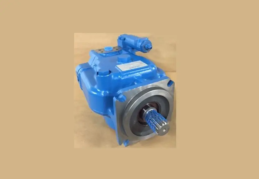
Danfoss PVH74-81 Variable Displacement Piston Pump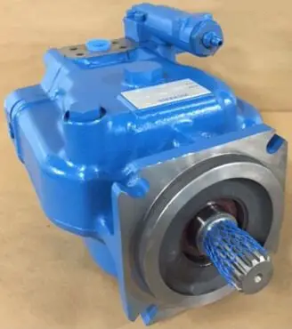
Maximum Adjustable Stop – S Option
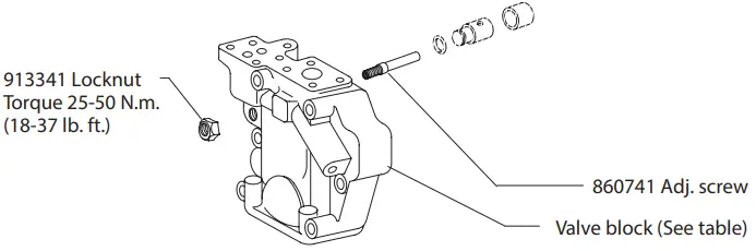
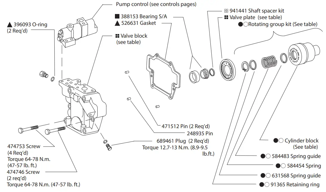
Valve Block Table
| Pump Type | RH | LH |
| F–11–C | 928633 | 928681 |
| M–11–C | 928634 | 928682 |
| SF–11–C | 928620 | 928669 |
| SM–11–C | 928621 | 928670 |
| F–11–CT | 860848 | 860857 |
| M–11–CT | 860849 | 860858 |
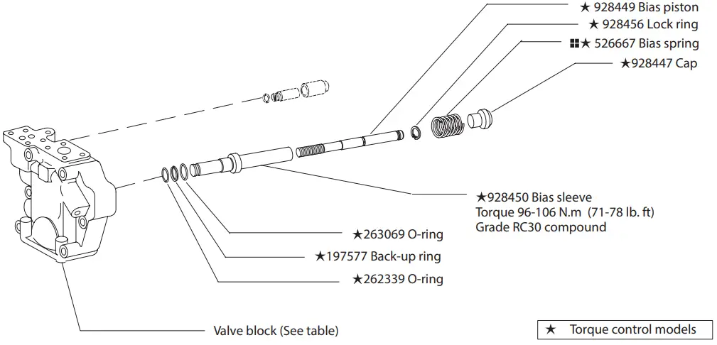
Torque Limiter – T Option
Standard – C/CM/CMV/CV/IC
| Housing | Flange/Seal |
| 526649 | -C-*S |
| 864498 | -C-*D |
| 860564 | -C2-*S |
| 860814 | -C2-*D |
| 864312 | -C3-*S |
| 883085 | -M-*S |
| Model Designation | Piston & Shoe S/A (9 req ’d) | Cylinder Block | Shoe Cage | Rotating Group Kit |
| 74 Size | 02-305857 | 937025 | 584774 | 877421 |
| 81 Size | 02-306364 | 937026 | 913956 | 02-314746 |
Valve Plate Table | ||
| Pump Type | RH | LH |
| 74 | 527438 | 627437 |
| 74Q1 | 513889 | 513890 |
| 74QP | 913741 | N/A |
| 81Q | 928405 | 928406 |
| 81QP | 928824 | N/A |
| Shaft | Type | Key |
| 692567 | 1 – Straight keyed 114 | 516 |
| 513865 | 2 – Splined | – |
| 883082 | N – Straight keyed 47 | 2287 |
| 864344 13 | – Straight keyed (thru) 14 | 0282 |
| 883229 | 2 – Splined (thru-036) | – |
| 864343 | 3 – Splined (thru) | – |
Note
Complete replacement via rotating group kits is recommended.
![]() Non-torque control models
Non-torque control models
![]() Available in double shaft seal kit 02 –102262
Available in double shaft seal kit 02 –102262![]() Available in bearing kit 877424
Available in bearing kit 877424![]() Available in bearing/yoke kit 02-334835
Available in bearing/yoke kit 02-334835![]() Available in PVH74 rotating group kit.
Available in PVH74 rotating group kit.![]() Available in PVH81 rotating group kit.
Available in PVH81 rotating group kit.
NOTE
Right hand rotation shown. View is opposite for left hand rotation.
Please refer to Overhaul Manual M-2210-S.
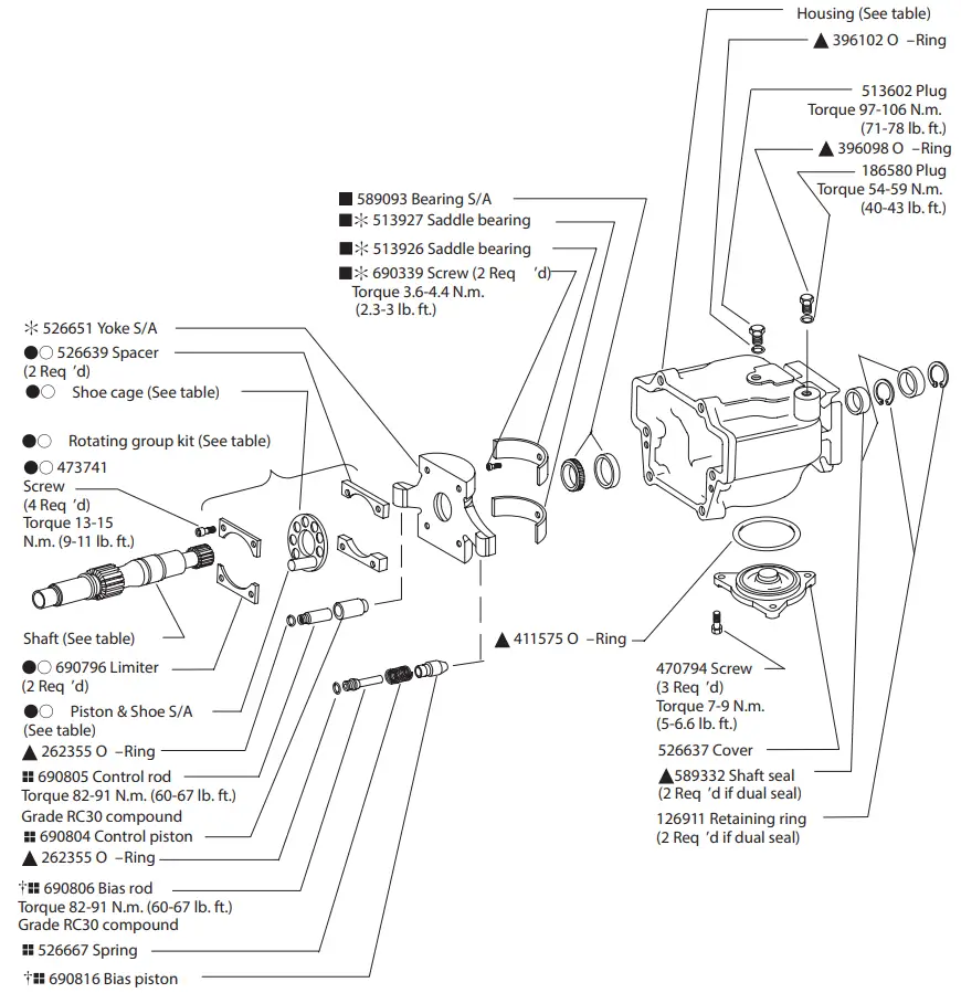
NOTE
Use shims as required to obtain 0.01 –0.10 mm (.0004 –.004 in.) axial shaft end play.
NOTE
For satisfactory service life of these components in industrial applications, use full flow filtration to provide fluid which meets cleanliness code 16/14/12 or cleaner.
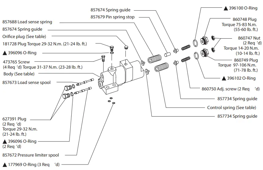
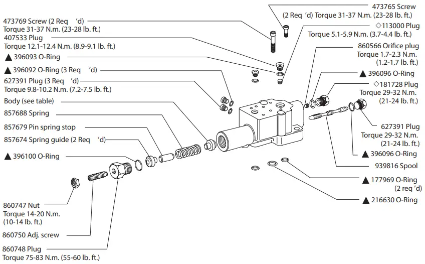
Load Sensing & Pressure Compensator Control C(M)*V
| Control Type | Control Kit | Pressure range | Spring | Body | Orifice Plug |
| CV | 02–125161 | 140 –280 Bar | 857681 | 857733 | – |
| CVB | 02–160591 | 928442 | 433543 | ||
| CMV | 02–306056 | 35–140 Bar | 857675 | 857733 | – |
All parts shown are included in control kit.
Pressures must be set by user to circuit requirements.
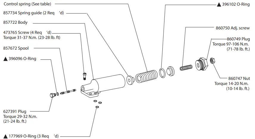
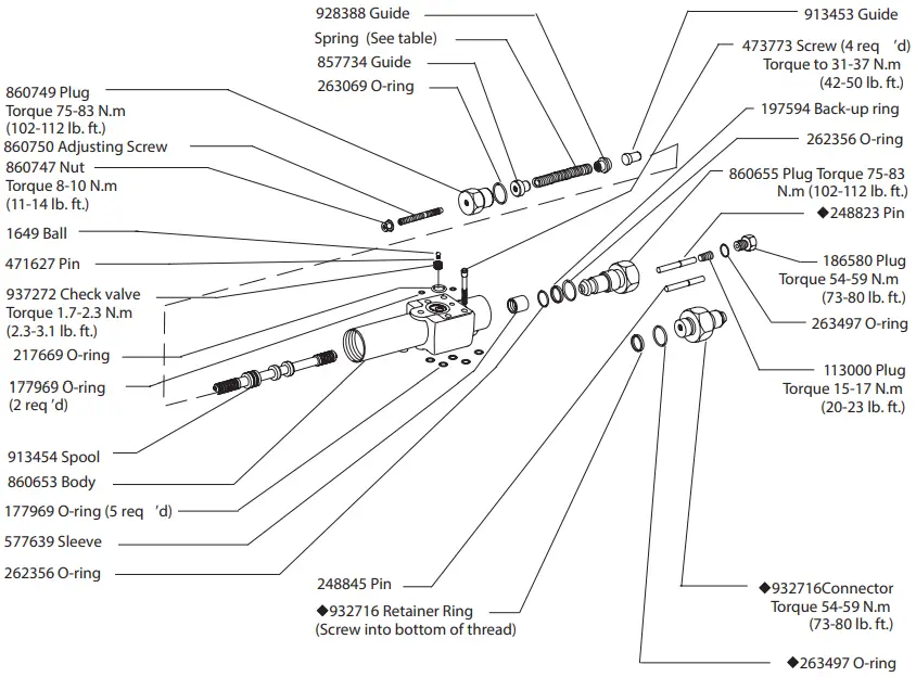
Pressure Compensator Control C & CM
| Control Type | Control Kit | Pressure range | Spring |
| C | 02–125160 | 140 –280 Bar | 857681 |
| CM | 02–125162 | 35–140 Bar | 857675 |
All parts shown are included in control kit.
Pressures must be set by user to circuit requirements.
Industrial Control (IC)
| Control Kit | Threads | Body |
| 02–151904 | inch | 883386 |
| 02–151905 | metric | 860628 |
All parts shown are included in control kit. Pressures must be set by user to circuit
requirements.
NOTE
IC kits pre-set to 20-30 bar differential pressure with all orifices/plugs in
place. Reference Vickers by Danfoss Overhaul Manual M-2210-S for proper
orifice/plug configuration in various circuits prior to control installation.
Torque Limiter – T Option
| Model designation | Control Kit | Spring |
| C**T**-31 | 02–314944 | 857675 |
| C**T**S-31 | 02–335254 | 857681 |
Torque summation parts
*A* Thru –drive
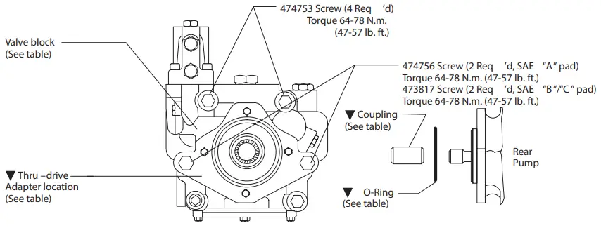
‘‘A’’ Thru –drive
| Model designation | Valve block w/ SAE ‘‘A’’ Pad | O-Ring | Coupling Type |
| LAF –11–C* | 928707 | 576601 | 864460 9 tooth SAE-A |
| LAM –11–C* | 928708 | ||
| RAF –11–C* | 928732 | ||
| RAM –11–C* | 928733 | ||
| LAF –11–CT | 860839 | ||
| LAM –11–CT | 860840 | ||
| RAF –11–CT | 860830 | ||
| RAM –11–CT | 860831 |
‘‘B ’’ & ‘‘C’’ Thru –drive Adapter
| Model Designation | Adapter Pad Kit | Adapter Flange | O-Ring | CouplingTypes |
| *–*BF –11–* | 876390 | 526670 | 401525 | 864457 SAE B – 13 tooth 864459 SAE BB – 15 tooth |
| *–*BM–11–* | 876394 | 876393 | ||
| *–*CF –11–* | 876389 | 692934 | 353264 | 864458 SAE C – 14 tooth 864461 SAE CC – 17 tooth |
| *–*CM –11–* | 876392 | 876391 |
Notes:
- ‘‘F ’’ type equal SAE threads
- ‘‘M’’ type equal metric threads
- ‘‘B’’ and ‘‘C’’ thru-drives created from ‘‘A’’ thru-drive pump with ‘‘B’’ or ‘‘C’’ thru-drive adapter kit installed.
- All screws/O-rings are included with each ‘‘kit’’ to convert from ‘‘A’’ to ‘‘B’’ or ‘‘C’’ thru-drive unit.
Typical Cross Section
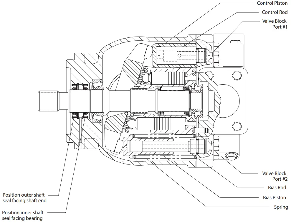
Note
Parts are shown as installed for right hand rotation. For left hand rotation, install control rod and control piston in valve block port #2. Install bias rod, bias piston and spring in valve block port #2.
Pump Startup
Make sure the reservoir and circuit are clean and free of dirt and debris prior to filling with hydraulic fluid.
Fill the reservoir with filtered oil to a level sufficient to prevent vortexing at suction connection to pump inlet. It is good practice to clean the system by flushing and filtering using an external slave pump.
Before starting the pump, fill with fluid through one of the ports. This is particularly important if the pump is above the fluid level of the reservoir.
When initially starting the pump, remove all trapped air from the system. This can be accomplished by loosening the pump outlet fittings or connections before starting the pump, or by using an air bleed valve. All inlet connections must be tight to prevent air leaks.
Once the pump is started, it should prime within a few seconds. If the pump does not prime, check to make sure that there are no air leaks in the inlet line and connections. Also check to make sure that trapped air can escape at the pump outlet.
After the pump is primed, tighten the loose outlet connections, then operate for five to ten minutes (unloaded) to remove all trapped air from the circuit. If reservoir has a sight gage, make sure the fluid is clear —not milky.
Add fluid to the reservoir up to the proper fill level.
Model Code
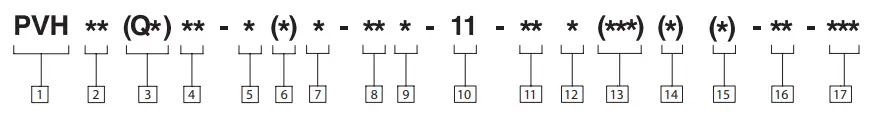
- Piston pump, variable displacement
- Maximum geometric displacement
74 – 73.7 cm 3/r (4.5 in 3/r)
81 – 80.9 cm 3/r (4.94 in 3/r) - Application style
Blank – Mobile application (rated speed & 250/280 bar (3600-4000 psi) pressures)
QI – Quiet industrial application (1500 – 1800 rpm & 250/280 bar (3600-4000 psi) pressures)
QP – Quiet power unit application (1800 rpm & 140 bar (2000 psi) max. pressures – R.H. rotation only) - Mounting flange, prime mover end
C – SAE “C” 4–bolt type (SAE J744-127-4 )
C2 – Optional combination 2- & 4-bolt SAE-C pilot
C3 – Optional 4-bolt SAE-C pilot for vertical pump mounting
M – Optional metric 4-bolt pilot ISO 3019/2-125B4HW (Must be used with ‘N’ shaft option.) - Shaft rotation, viewed at prime mover end
R – Right hand, clockwise
L – Left hand, counterclockwise Configuration - Blank – Non-thru-drive (single pump)
A – SAE-A thru-drive pump, standard (SAE J744-82-2)
B – SAE-B thru-drive pump, optional (SAE J744-101-2/4)
C – SAE-C thru-drive pump, optional (SAE J744-127-2/4)
S – Adjustable maximum volume stop ( ‘‘S ’’ option not available on thru-drive and torque control pump models.) - Main ports 13
F – SAE 4-bolt flange ports (standard)
M – SAE 4-bolt pads with metric mounting bolt threads - Shaft-end type, at prime mover end
N – Metric ISO short straight key (ISO 3019/2-E32N for ‘‘M’’ pilot only)
1 – SAE-C straight key
2 – SAE-C 14 tooth spline
3 – SAE-CC 17 tooth spline
13 – SAE-CC straight key - Shaft seal, prime mover end
S – Single, one-way
D – Double, two-way - Pump design number
11 – (Subject to change. Installation dimensions unaltered for design numbers 10 to 19 inclusive. ) - Pressure control type
C – Compensator, 140-280 bar (2080-4000 psi)
CM – Compensator, 35-140 bar (50-2000 psi)
IC – CETOP 3 interface compensator,
20 bar factory ‘‘differential’’ pressure setting (QI and QP models only) - Factory compensator pressure setting
Blank – Leave blank for ‘‘IC ’’ controls only
7 – 70 bar (1015 psi) normal ‘‘CM7 ’’ setting (all pump sizes)
23 – 230 bar (3335 psi) normal ‘‘C23 ’’ setting (63, 81, 106, 141 models)
25 – 250 bar (3625 psi) normal ‘‘C25 ’’ setting (57, 74, 98, 131 models) - Optional pressure control functions
Blank – Leave blank for basic compensator controls of IC models.
V – Load sensing, 20 bar (290 psi) factory ‘‘differential’’ pressure setting
T – Torque limiting control (Used with sections [14] and [15].
VT – Load sensing with torque limiting
VB – Load sensing with internal bleed down (0.15 ” dia. orifice)
VBT – Load sensing with internal bleed down and torque limiting
Torque limiting control pressure setting
Blank – Leave blank if no torque limiting control is used
4 – Standard minimum 40 bar setting of
‘‘T’’ torque control option - Torque limiting control summation
Blank – Standard torque control
S – Optional torque control with summation feature - Control design number
31 – All control options - Special feature suffix
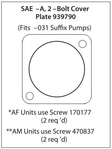
031- Mounting with SAE-A, 2-bolt cover plate
036- #2 ‘‘C’’ spline shaft in thru-drive pumps***
![]() ***CAUTION
***CAUTION
Maximum shaft input torque must not exceed 5660 lb-in.
Products we offer
- Cartridge valves
- DCV directional control valves
- Electric converters
- Electric machines
- Electric motors
- Gear motors
- Gear pumps
- Hydraulic integrated circuits (HICs)
- Hydrostatic motors
- Hydrostatic pumps
- Orbital motors
- PLUS+1® controllers
- PLUS+1® displays
- PLUS+1® joysticks and pedals
- PLUS+1® operator interfaces
- PLUS+1® sensors
- PLUS+1® software
- PLUS+1® software services, support and training
- Position controls and sensors
- PVG proportional valves
- Steering components and systems
- Telematics
Danfoss Power Solutions is a global manufacturer and supplier of high-quality hydraulic and electric components. We specialize in providing state-of-the-art technology and solutions that excel in the harsh operating conditions of the mobile off-highway market as well as the marine sector. Building on our extensive applications expertise, we work closely with you to ensure exceptional performance for a broad range of applications. We help you and other customers around the world speed up system development, reduce costs and bring vehicles and vessels to market faster.
Danfoss Power Solutions – your strongest partner in mobile hydraulics and mobile electrification.
Go to www.danfoss.com for further product information.
We offer you expert worldwide support for ensuring the best possible solutions for outstanding performance. And with an extensive network of Global Service Partners, we also provide you with comprehensive global service for all of our components.
Customer Service
Hydro-Gear
www.hydro-gear.com
Daikin-Sauer-Danfoss
www.daikin-sauer-danfoss.com
Danfoss
Power Solutions (US) Company
2800 East 13th Street
Ames, IA 50010, USA
Phone: +1 515 239 6000
Danfoss
Power Solutions GmbH & Co. OHG
Krokamp 35
D-24539 Neumünster, Germany
Phone: +49 4321 871 0
Danfoss
Power Solutions ApS
Nordborgvej 81
DK-6430 Nordborg, Denmark
Phone: +45 7488 2222
Danfoss
Power Solutions Trading
(Shanghai) Co., Ltd.
Building #22, No. 1000 Jin Hai Rd
Jin Qiao, Pudong New District
Shanghai, China 201206
Phone: +86 21 2080 6201
Danfoss can accept no responsibility for possible errors in catalogues, brochures and other printed material. Danfoss reserves the right to alter its products without notice. This also applies to products already on order provided that such alterations can be made without subsequent changes being necessary in specifications already agreed.
All trademarks in this material are property of the respective companies. Danfoss and the Danfoss logotype are trademarks of Danfoss A/S. All rights reserved.